2. Computer-Aided Design
model (raster, vector, 2D, 3D, render, animate, simulate, ...) a possible final project, compress your images and videos, and post a description with your design files on your class page.
For this week I wanted to compare the two compliant mechanisms from these websites:
Complex Mechanism:
https://www.youtube.com/watch?v=cBw3fmHBnd4&list=PLESMsPZHhcwWFEfm7F3qNj3XFKn1SqLQ3&index=9&t=140s
Simple Mechanism:
https://www.thingiverse.com/thing:5436842
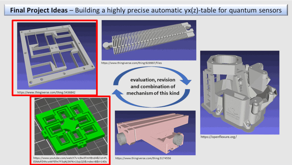
I wanted to know which of these mechanisms is more suitable for my final project concerning:
- maximal displacement of the stage in the middle
- maximal stress in the geometry when actuated
- unwanted rotational displacements
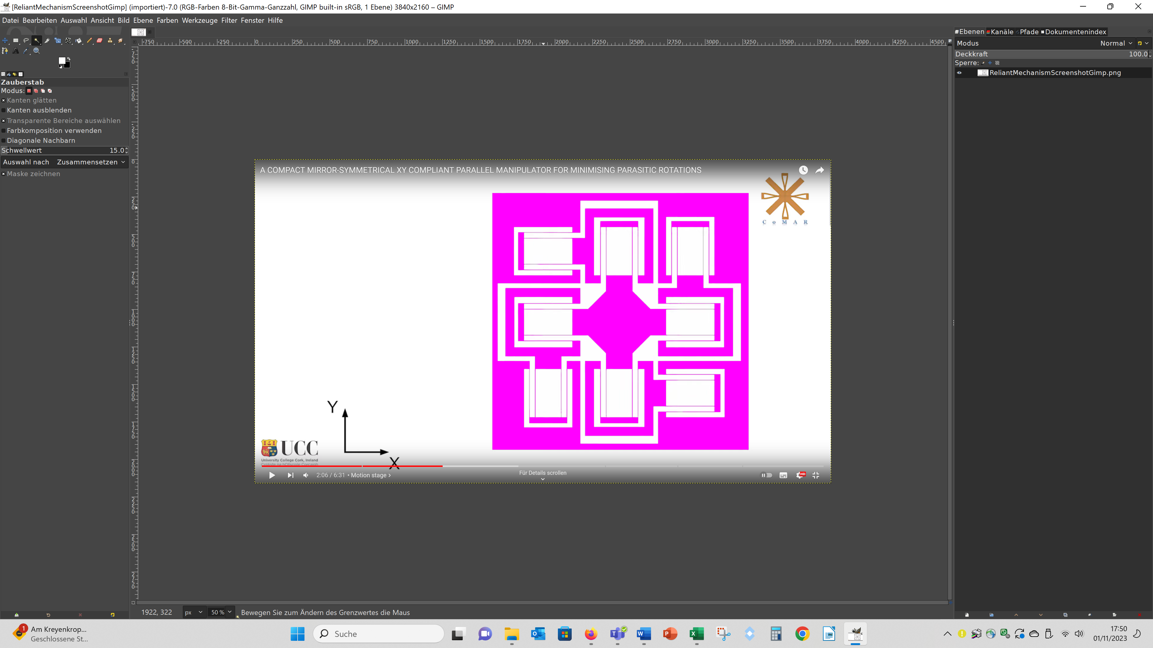
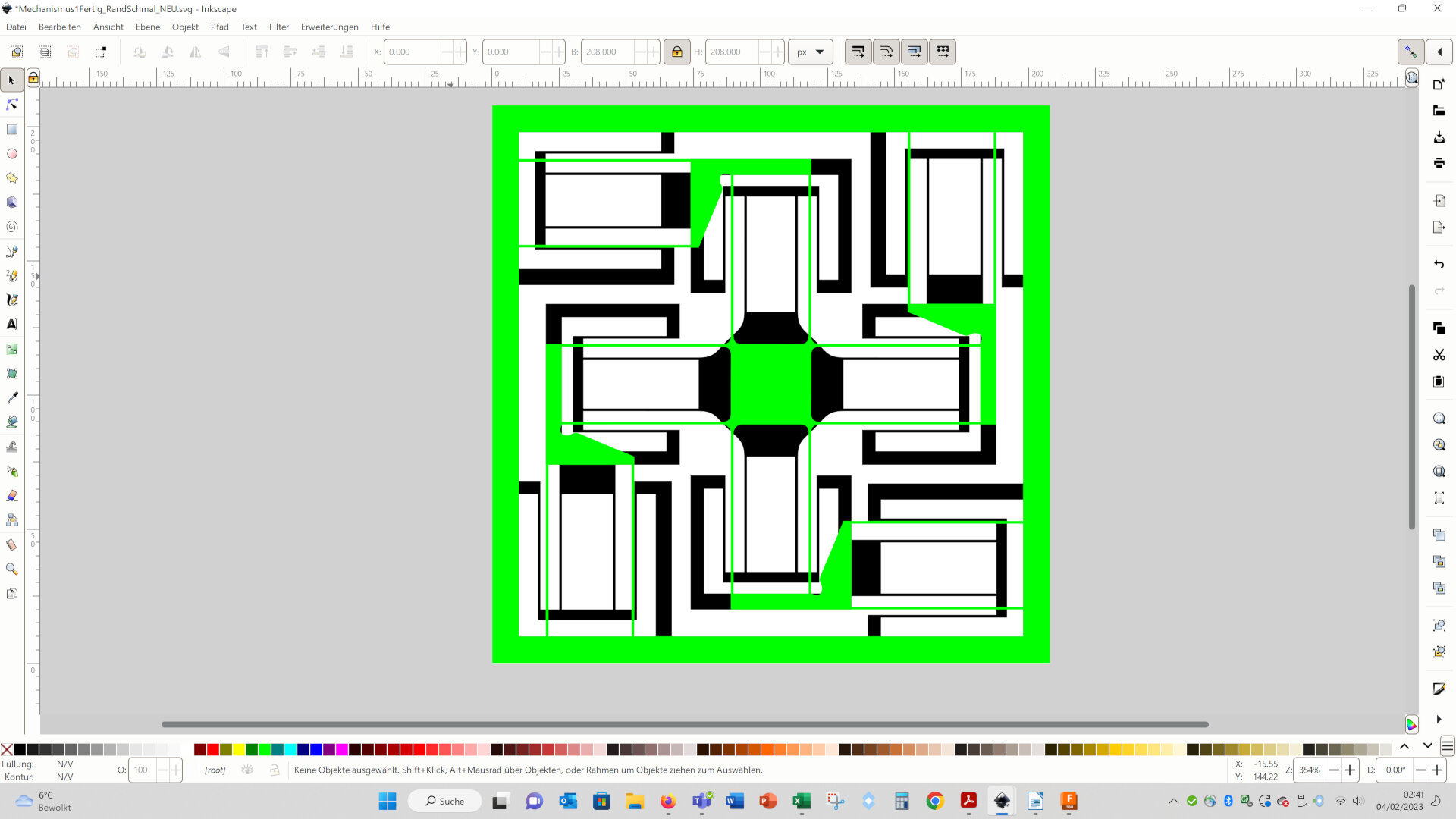
To analize these properties I made finite element simulations of the geometries using Fusion 360. But first I had to construct the two 3D geometries. For the complex mechanism I stated with a screenshot of the video, edited it in Gimp. Therefor, I performed a levels, converted the image in a black and white image, marked the region of the mechanism with the wand, so that it is selected:
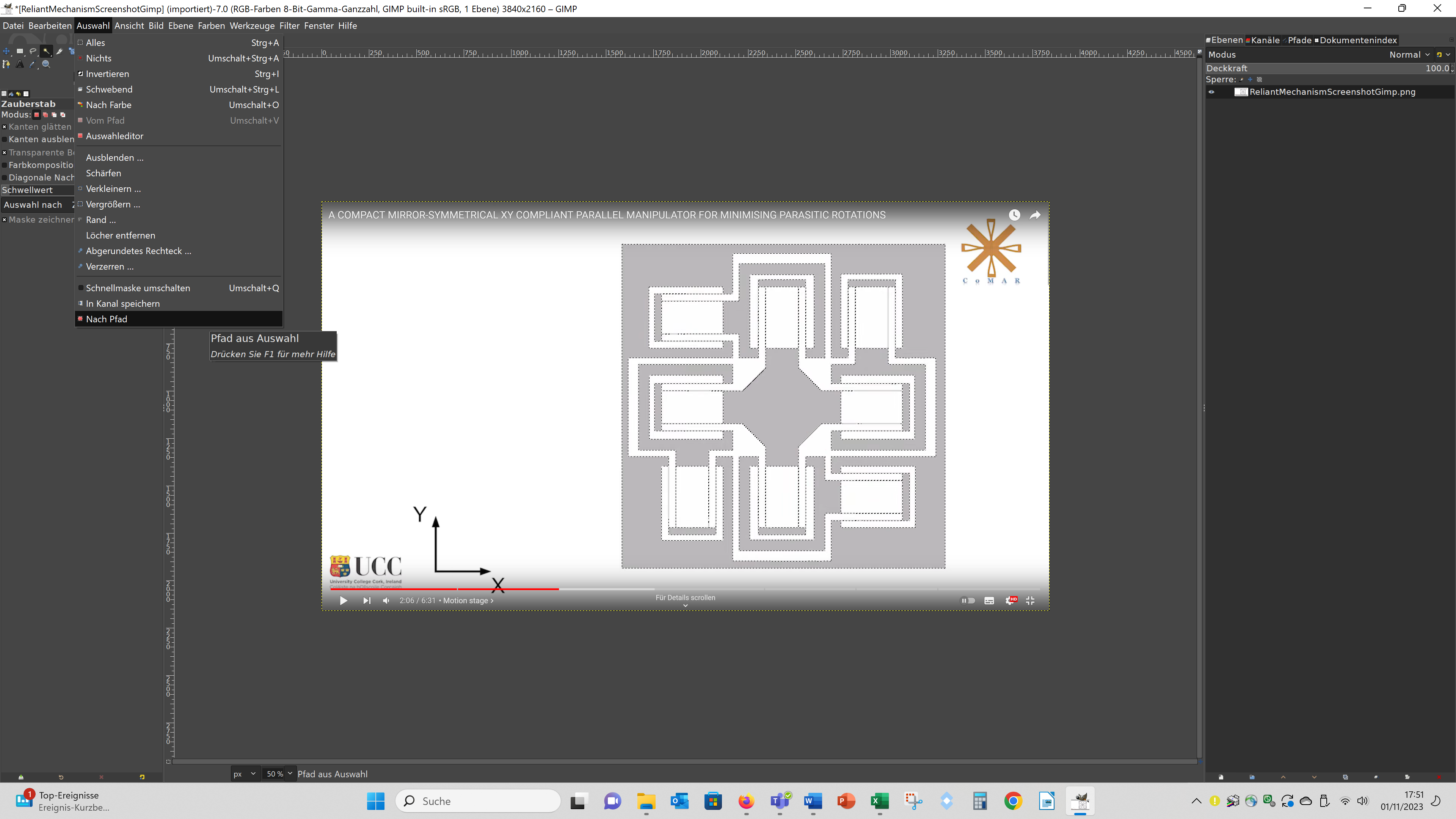
Then I clicked on "Auswahl" and "Nach Pfad":
Then I right clicked on the path in the path menue, choose - "Pfad exportieren", entered a filename with the ending .svg and saved a svg of the contour.
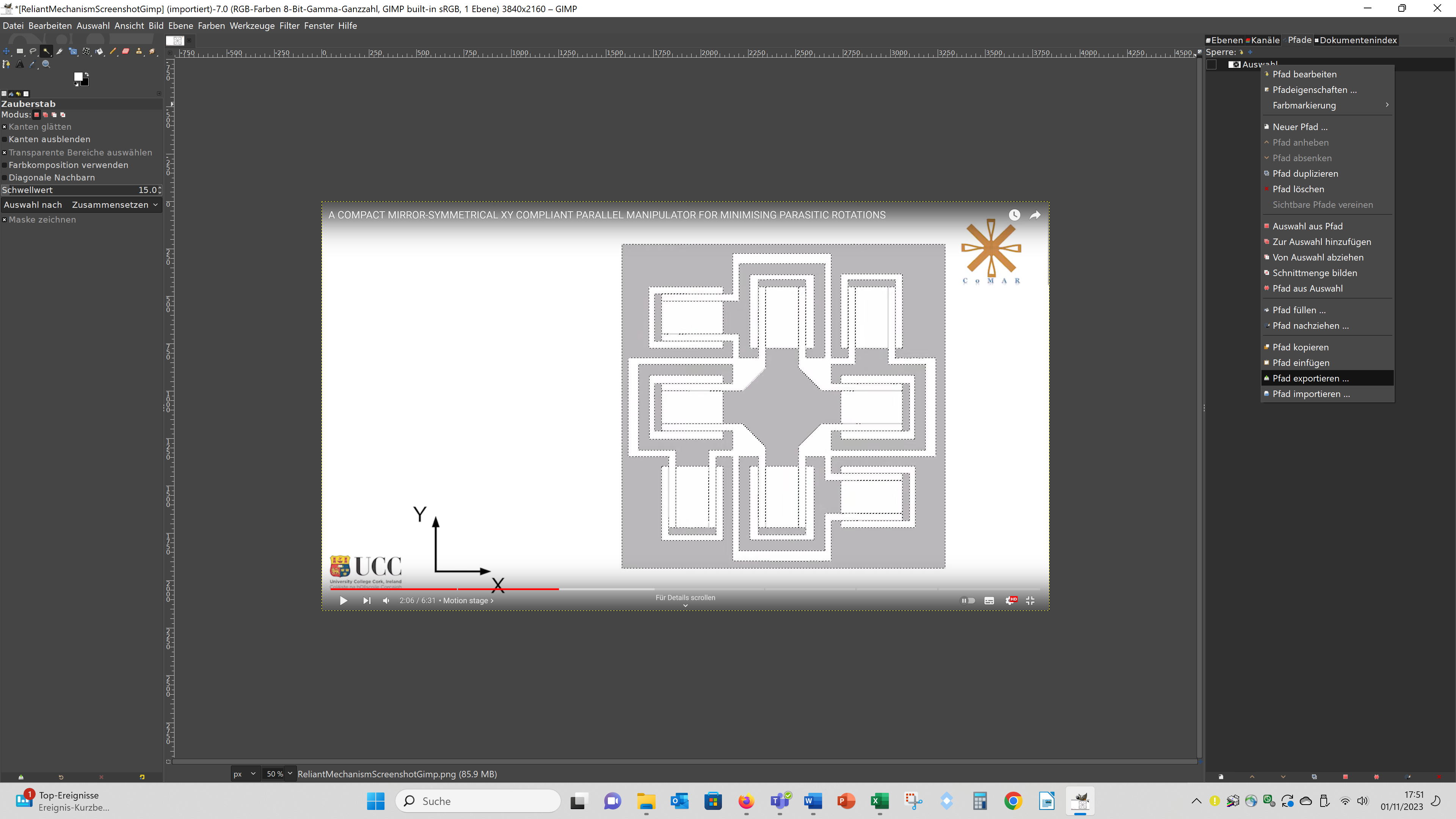
I also tried to generate a svg directly using Inkscape by using the function "Pfad - Bitmap nachzeichnen", but this led to worse results than compiling the svg in Gimp, because the paths showed much more nodes leading to unclean edges. For the simple mechanism I downloaded the stl from thingiverse, but because I wanted to edit the geometry I used the program slic3r to generate a svg from it. When you go to file – slice to svg, you can export a svg file from the 3D geometry. This svg file contains many of the contours of the 3D geometry, because these svgs are actual meant to use them in a SLA-3D printer. So you have to pic the first contour, push it aside and delete the remaining contours. make the comparison more meaningful I adapted the svg files of both geometries to each other, so that they have the same size, the beams had the same thickness and the moveable part of the geometry have also the same size:
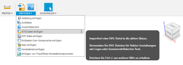
Then I inserted the svg files into Fusion 360 (Einfügen – SVG-Datei einfügen, engl.: ~ Insert – Insert SVG-Data):
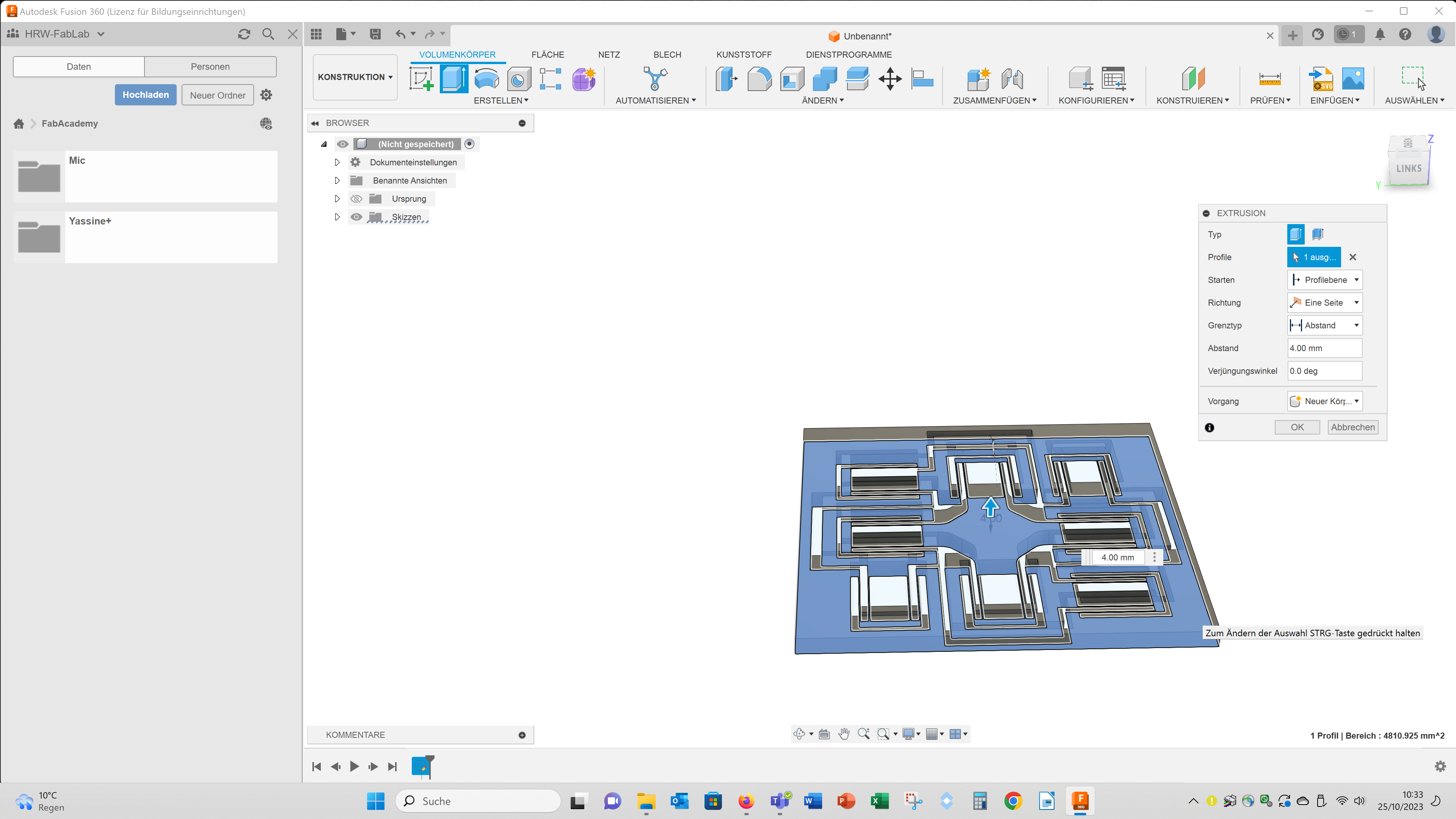
Then I resized the svgs to a size of 50x50 mm (Ändern – Maßstab, engl.: ~ Change – size). Then I extruded the svgs 4 mm (Extrusion):
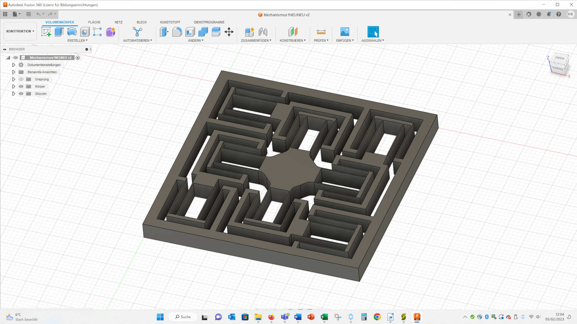
For the complex mechanism the final geometry looked like this:
I also used the software ImageJ to compile 3D gemetries, but this process has several disadvantages: sharp corners get rounded, the stl file is very large and curves get cornered. I described the process of compiling 3D geometries out of 2D images with ImageJ in the folloging video: https://www.youtube.com/watch?v=pto5LBD4za8
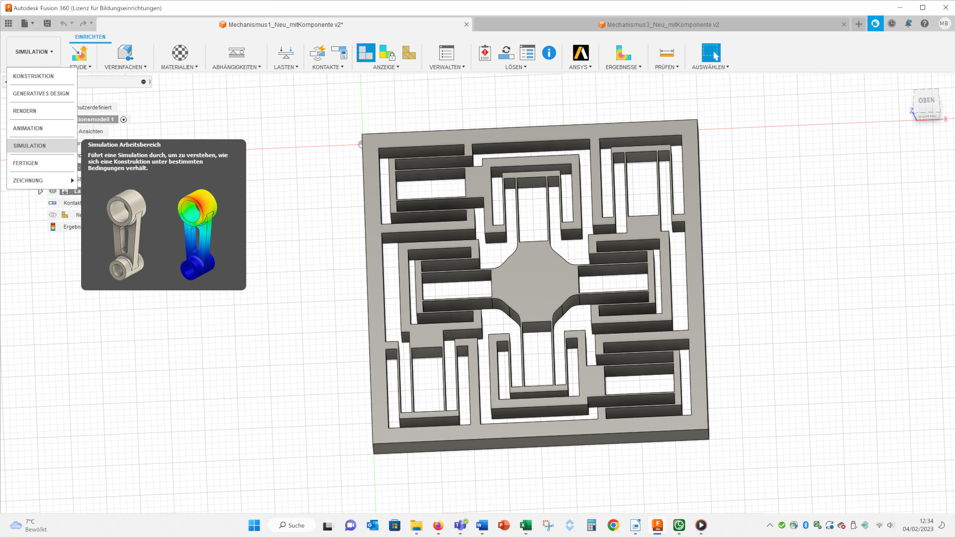
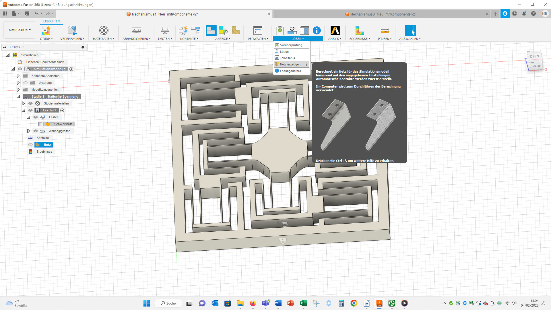
The steps to make a finite element simulation I show for the complex model, but for the simple model the procedure is (nearly) the same. To make a simulation go to simulation and choose “Statische Spannung” (~ engl.: static stress):
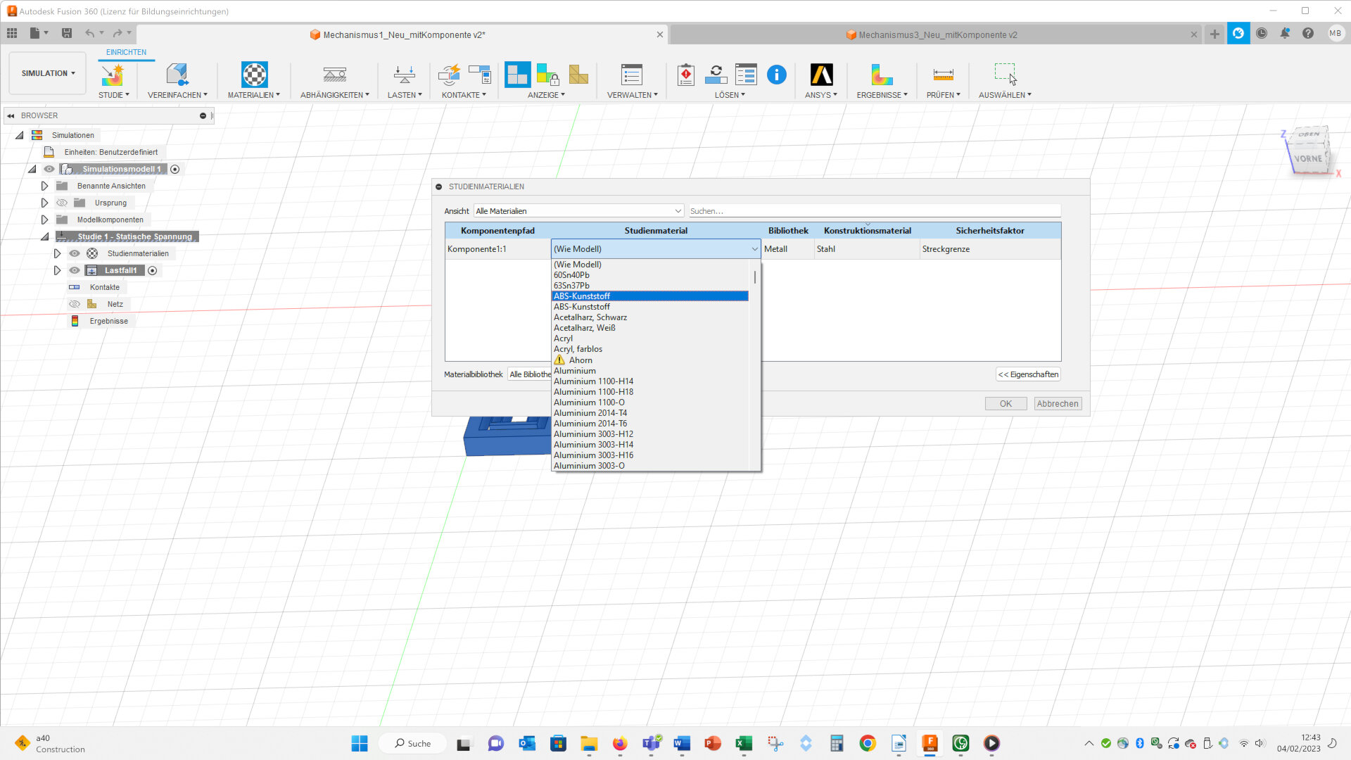
First you have to select a material. I choose ABS, because I want to 3D print the geometry:
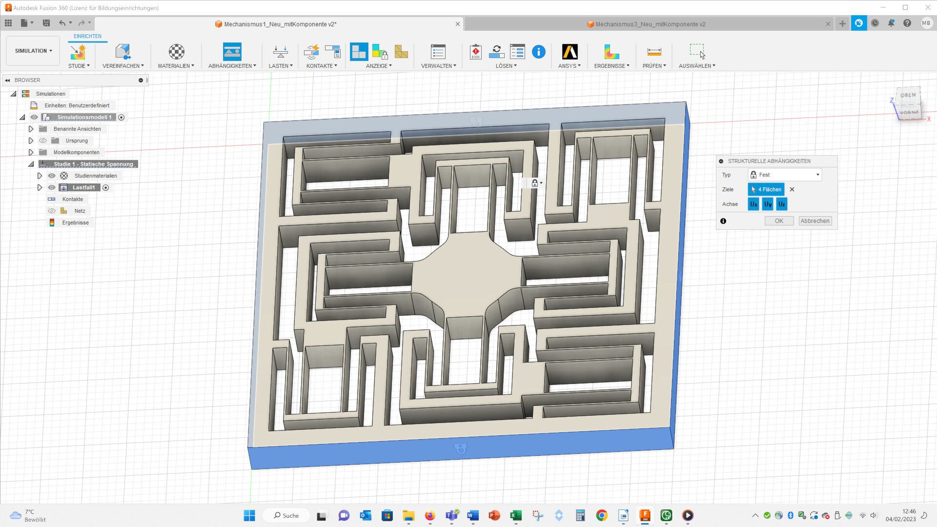
Than you have to fix the outer walls of the geometry (Abhängigkeiten, ~ engl. : dependencies):
Then I applied a forced displacement (Lasten – Strukturelle Lasten – Zwangsverschiebung, ~ engl.: load – structured load – forced displacement):
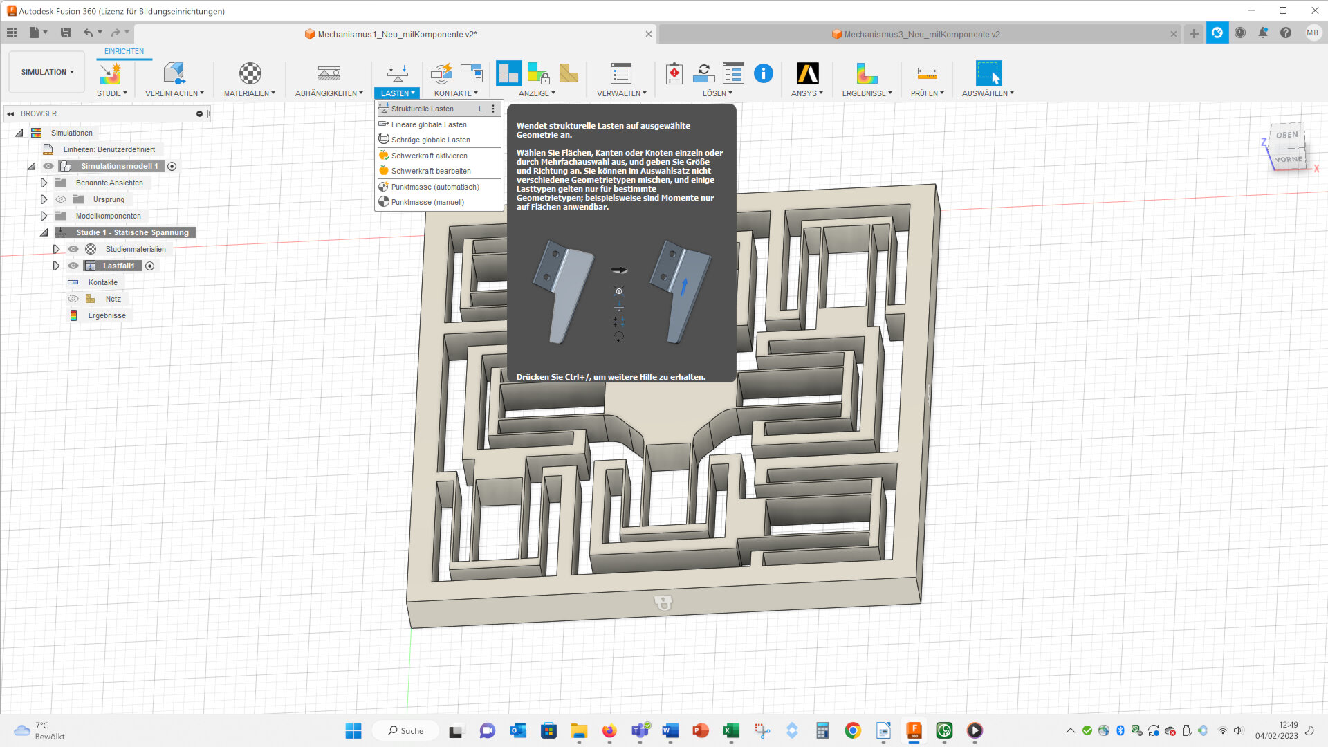
On the two faces I highlighted with arrows I applied a forced displacement of 1.6 mm in the directions of the arrows.
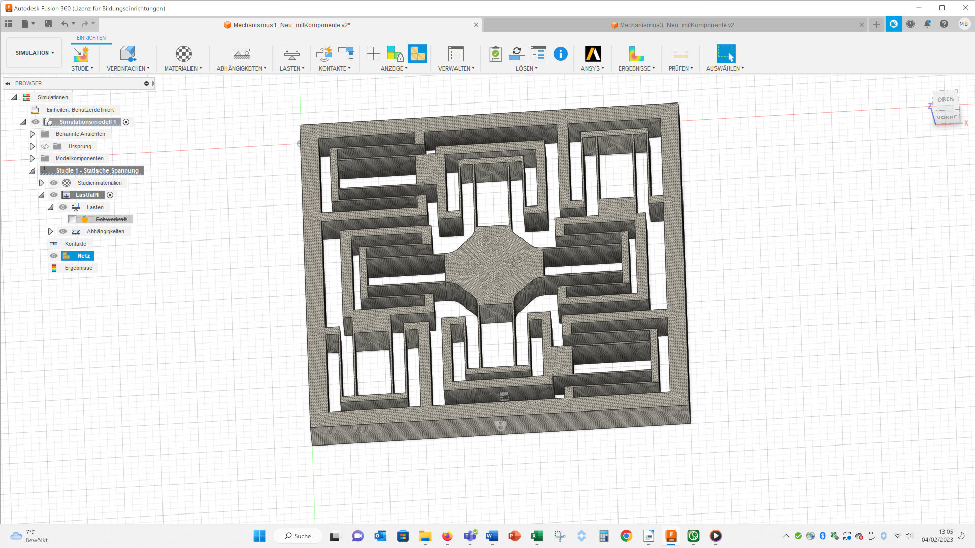
Then I created a mesh with an edge length of 0.24 mm, because the width of the beams has this thickness (it would be better to mesh the beams in at least 3 elements, but because of the calculating time I decided to use only one element).
Here you can see the final mesh:
Then you can solve the simulation (Lösen – Lösen, ~ engl.: Solve – Solve).
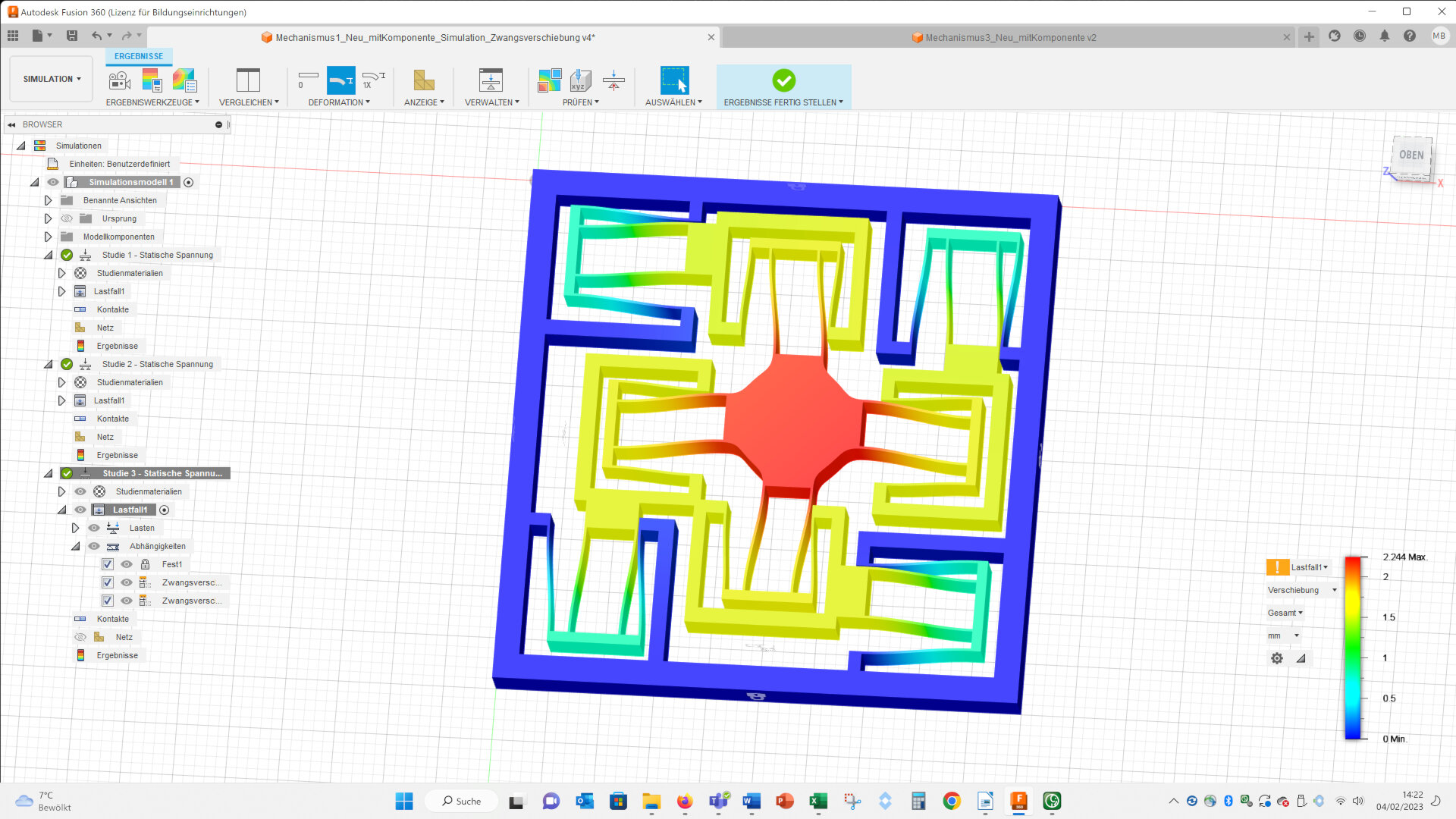
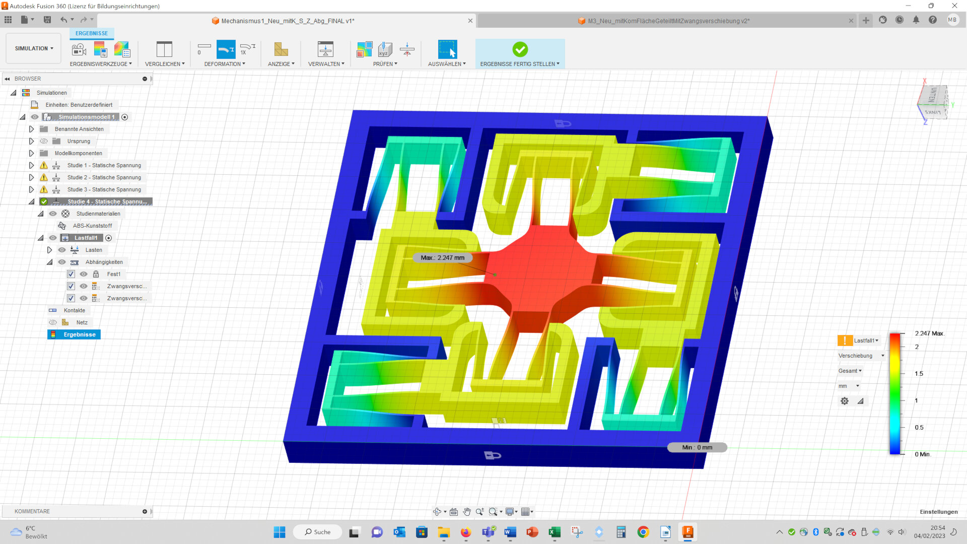
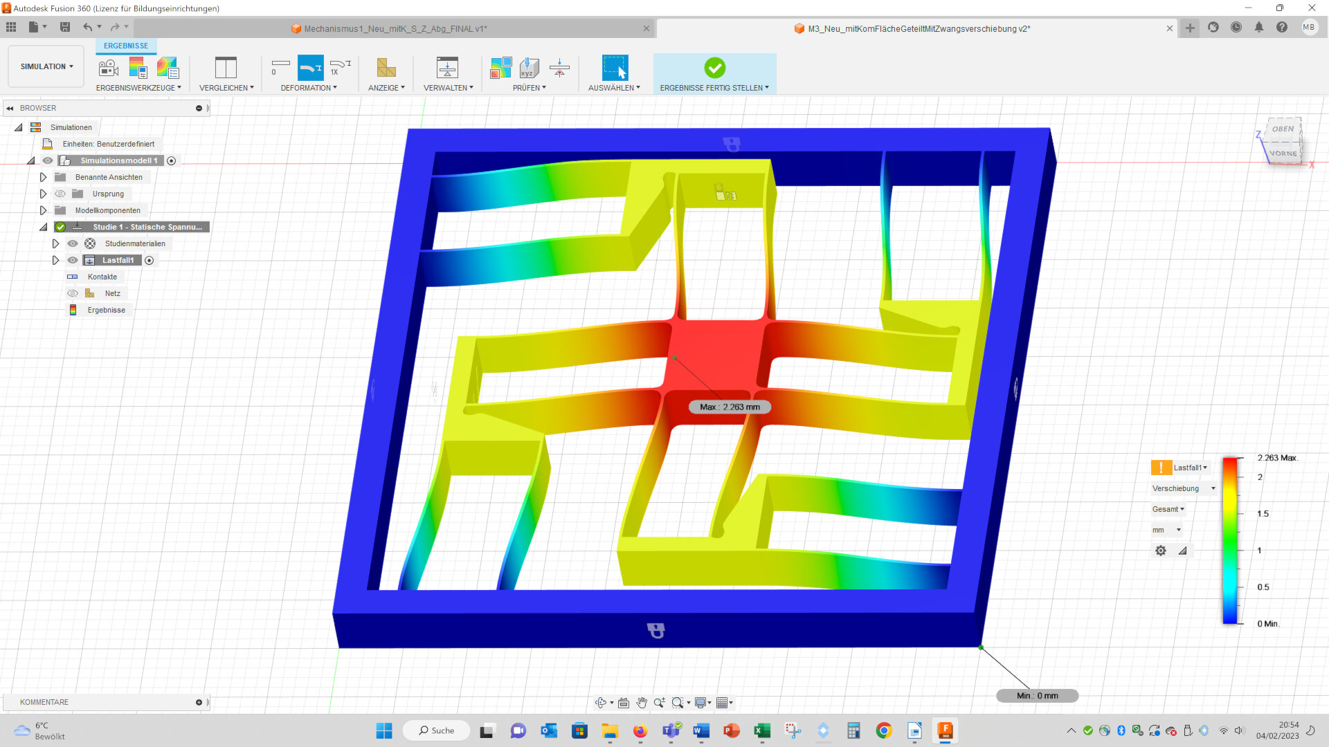
Here you can see the deformation of both geometries:
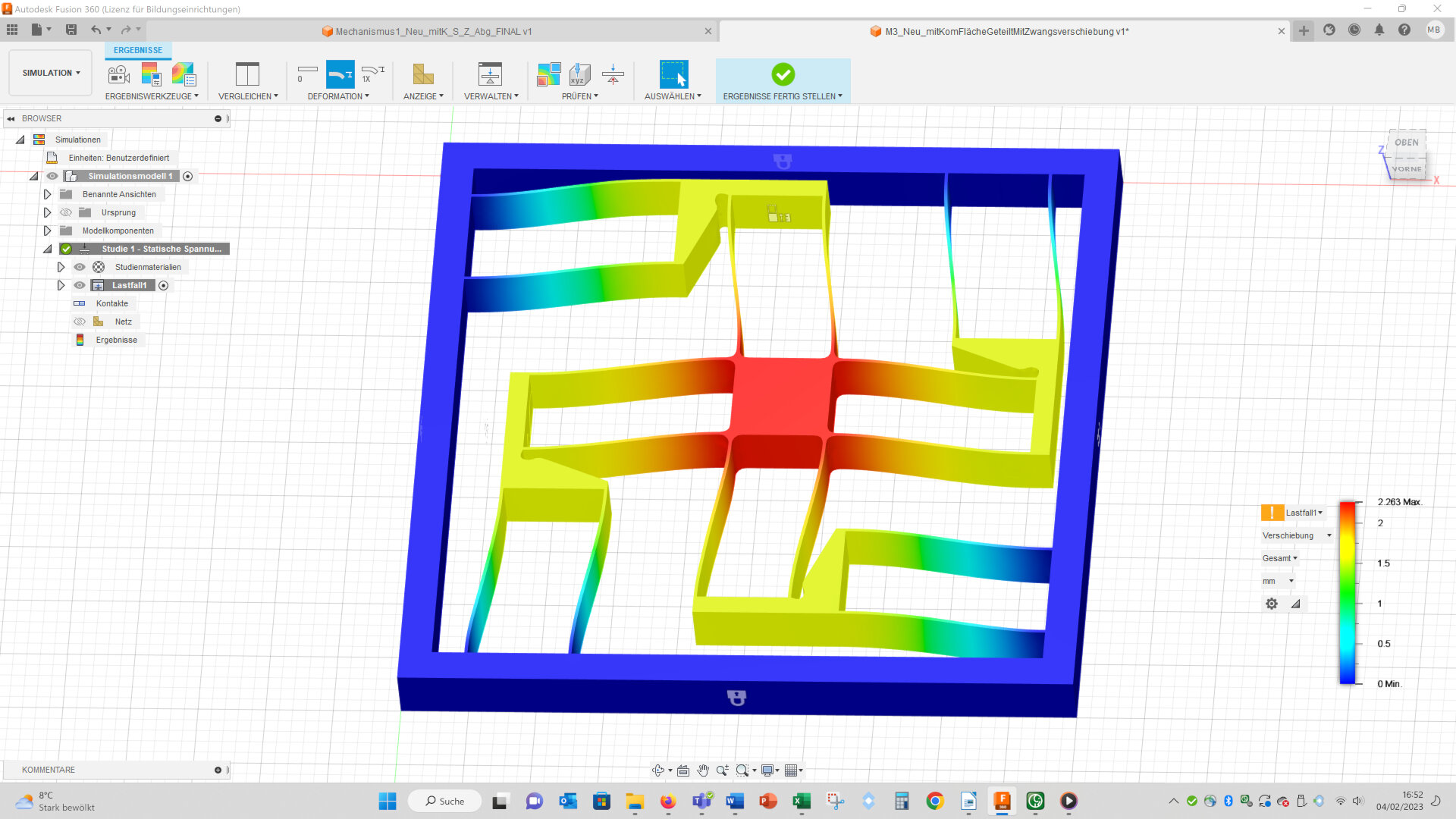
And videos of the deformation of both geometries:
The maximal displacements of both geometries are nearly equal (complex: 2.247 mm vs. simple: 2.263 mm):
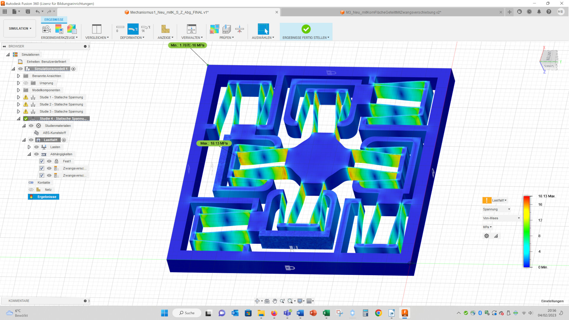
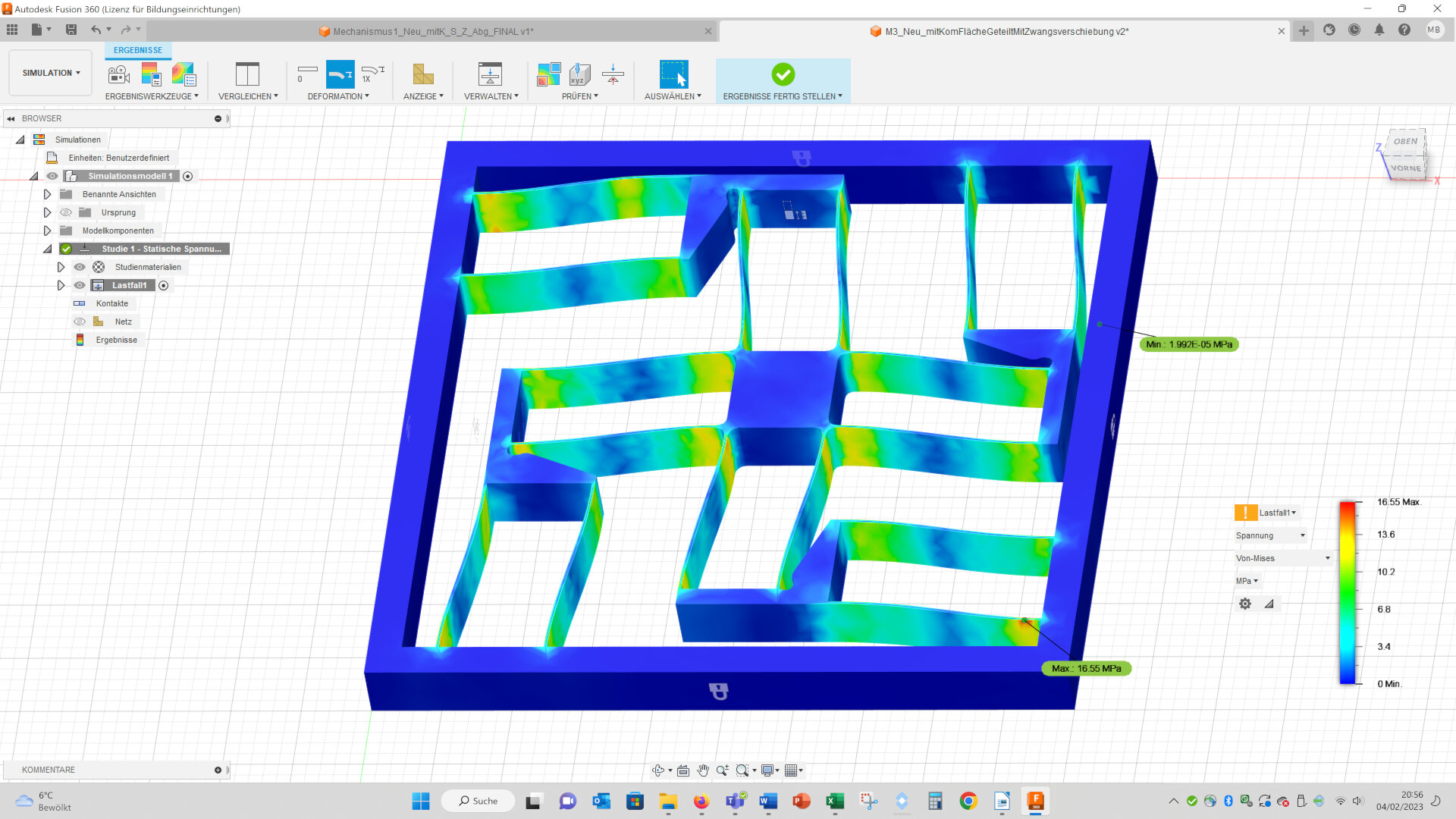
The maximal von Mises stresses are a bit higher in the complex geometry (complex: 18.13 MPa vs. simple: 16.55 MPa):
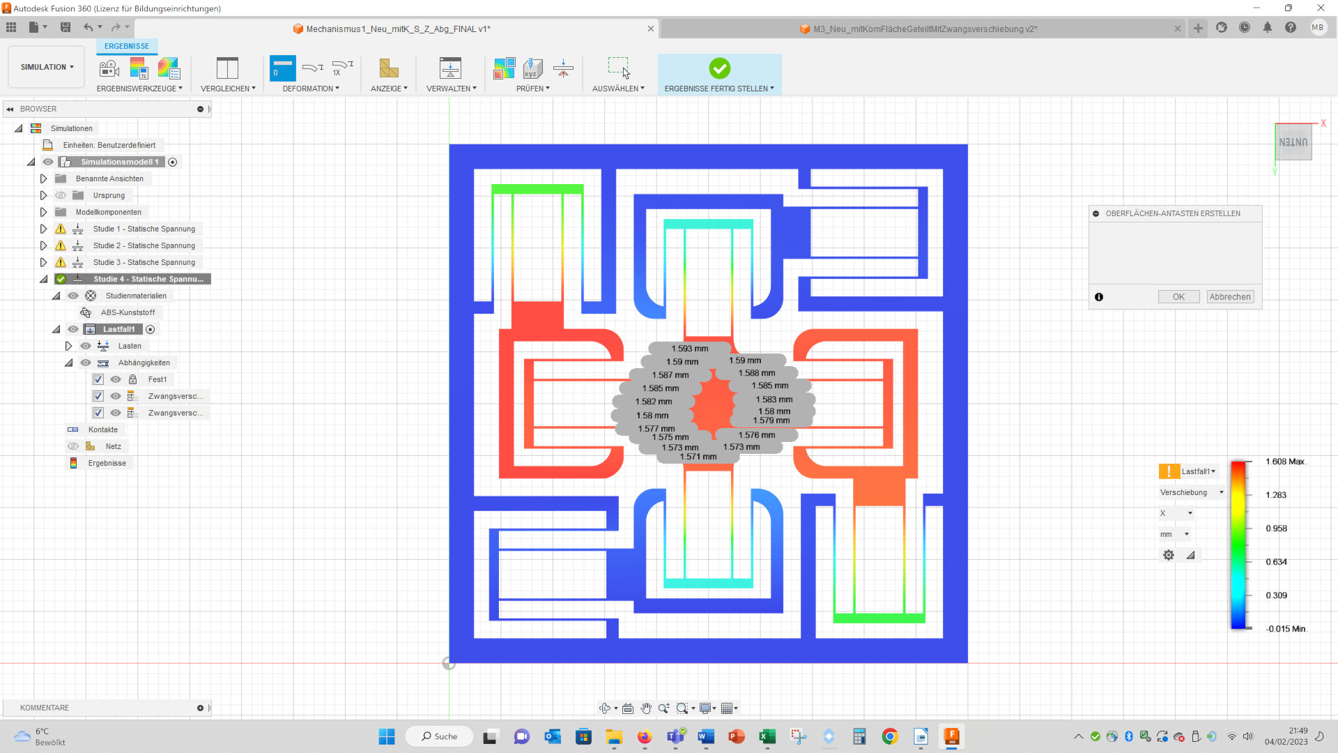
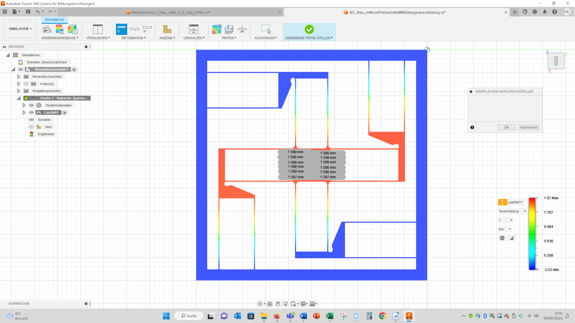
I measured the x- and y-displacements at the corners of the stage in the middle. In the complex geometry the upper corners have a larger displacement than the lower corners. This means, that the stage of the complex geometry shows a larger circular movement than the simple geometry:
Summing up, the simple geometry shows lower maximal stresses, the potential maximal displacements are higher (you can apply a higher forced displacement, without the internal structures touching each other), the circular movement of the stage is smaller and it is easier to apply changes to the geometry, so in the further course I will use the simple geometry. The results of the finite element simulation are kind of surprising for me, because I thought the complex geometry would perform better. But, perhaps I misinterpret the results or neglect important aspects – what do you think?
This side I again build with LibreOffice (see week 1). The images I compressed with Bimp and the videos with Handbrake.
I don´t offer the design files I created for download, because I don´t want to infringe the property rights of the original designers. But below you can download the final designs of reliant mechanisms I designed by myself. For details please visit my final project page.
Downloads
The following files you can use under the Creative Commons-Licence: CC BY-ND 4.0
Please cite: © Dr. Michael Bennemann