19. Project development
assignement - consider the following points
Complete your final project, tracking your progress:
> The final 3D print of the reliant mechanism should be finished.
> The limit switches have arrived and fit (after some adjustments) in the reliant mechanism.
> Actually, I write the code so that the stepper motors, the photosensor, the limit switches and the display work together.
> Further, I record videos for the final presentation and finalise the documentation of all weeks.
what tasks have been completed, and what tasks remain?
> The final ODMR device has to be assambled and programmed.
> The documentation of the most week is finised.
> The group assignements of week 3 and 14 have to be finished.
what's working? what's not?
> I want to improve the slicing of the reliant mechanism, because the flexible parts are sometimes fragile.
> Update: I changed from a prusa to a bambu 3d printer and found a setting so that the flexible parts are printed robust.
what questions need to be resolved?
> I have to learn how to edit videos. I plan to use the free software DaVinci Resolve.
> Update: I started a Udemy course about video editing with DaVinci Resolve and cut the first video and made a frame laps of milling a pcb.
> I have to adjust the pcb for the final project, so that I can use a Xiao rp2040 µC, which can be surface mounted.
what will happen when?
> I think I have enough time to finish everything in time, if nothing unforeseen comes up.
> When I can not manage to get all planned components to work, I will shrink my final project a bit.
> I hope that it is then still sufficiant as a final project.
what have you learned?
> a looot! Especially, I deepened my knowlege about pcb fabrication, programming and CNC milling.
> This encouraged and motivated me to dive deeper esprecially into CNC milling.
> I will proceed to work on my CNC machine build in week 10 and want to mill complex 3D dimensional geometries.
Development of my final project
Since the beginning of the year 2023, I am working in the field of quantum sensor technology.
The goal of our Quantum Technology FabLab working group
https://www.qufablab.de/de/ and our cooperation partners is to construct inexpensive quantum sensors, which can be used for education, research and as industrial sensor.
To build such a quantum sensor, it is necessary to align a suitable diamond very precisely in the beam path of the laser.
At the start of the fabacademy I planned to construct a motorized xy-table to align the diamand in the beam of the laser as my final project in the FabAcademy.
This table could also be used to measure magnetic fields in 2D using the quantum sensor or to build a scanning laser microscope and much more.
I decided to build the xy-table by using a reliant mechanism, since it combines the x and y motion in one layer.
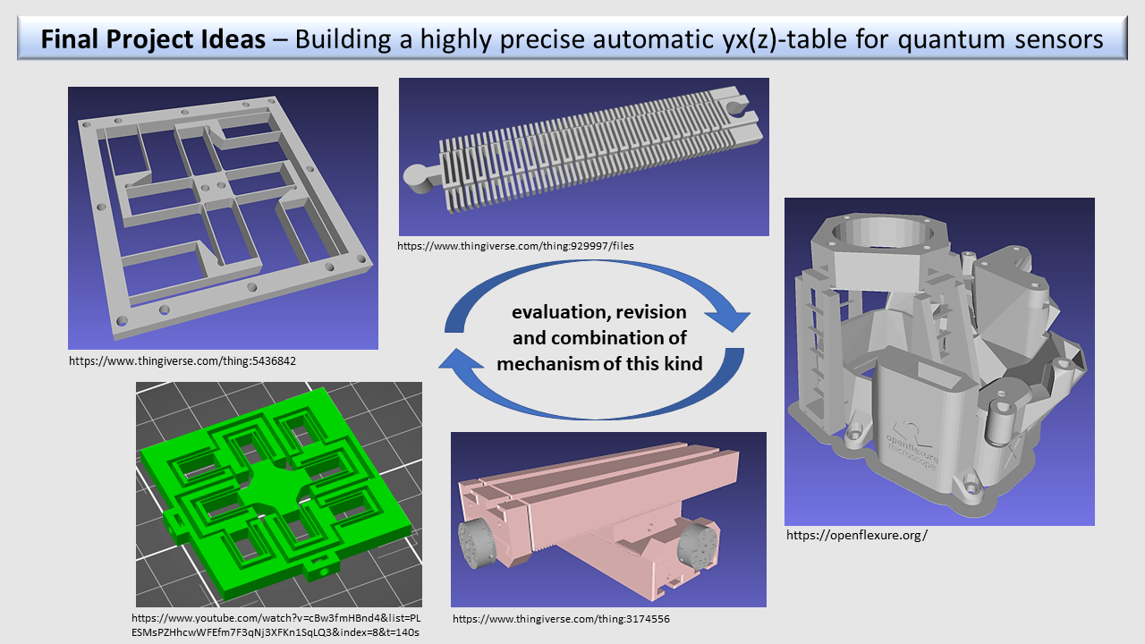
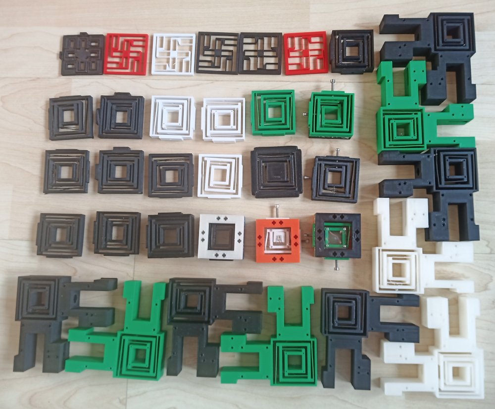
To design a reliant mechanism I tried out serveral geometries and finaly desigened my own one.
The reliant part ot the mechanism is only one 3D path (0.38 mm) thick, so this seems to be the smallest geometry for a reliant mechanism, which can be printed with a FDM modeling 3D printer.
The reliant mechanism is 48x48 mm large and has a compatible lare radius of movement of 5x5 mm.
The other meanisms I recreated (see first designs in the image below) had quite low radii of movements, so I deceided to design my own one.
I does not use a dubble set of flexible beams, to gain radius of movement and mirrowed the attachment of one side of the reliant mechanism to prevent a rotational movement.
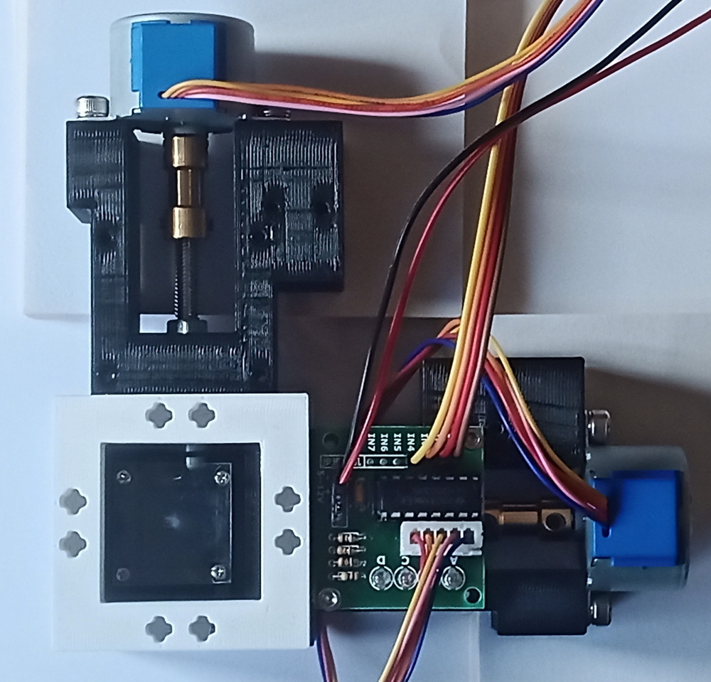
I use this mechanism two times in my setup. Once to move the diamond in the focus of the laser, and another time to move the photodiode manually in the focus of the second lens.
The motorized reliant mechanism is powered by two 28byj-48 stepper motors.
The shafs are coupled to headless M5 screws.
These are threaded in hexagonal long nuts.
The long nuts reach in hexagonal holes in the reliant mechanism.
This prevents the long nut from turning, so it is forced to move forwards or backwards, when the stepper motor is turning.
Here you can see most of my 3d prints of the reliant mechanism in my journey to optimise it:
And here you can see the final reliant mechanism.
One stepper motor driver is attached the other not the show the mechanism of the linear guidance.
Later I attached the drivers to the back side of the reliant mechanmis.
In the square-shaped middel of the reliant mechanism a transparent pcb foil with NV-diamands is located.
The dimonds are glued to the foil usind superglue.
The foil is attached to the reliant mechanism with tiny glasses and watch screws.
The reliant mechanism moves the diamonds in x- and y- direction in a serpentine-like movement.
Acutally the stepper motor for the x-axis makes 10 steps, than the motor for the y-axis makes one step and the motor for the x-axis makes 10 steps back.
This process is done till the reliant mechanism moved to 100 different positions.
At every position the fluorescent intensity of the diamonds will be measured.
By this procedure an adjustment of the diamand to the laser can be found.
Later I will try to programm another algorithms, with which a good adjustment can be found faster.
The 28byj-48 stepper motors have a high translation of 4096 steps per revolution, which is good for accurateness, but the process to move to 100 positions needs about 8 minutes.
I optimised the reliant mechanism to print it on a bambu 3d printer. For other pinters you probalby need to adjust the geometry.
It is important, so that the flexible part of the mechanism is securly attached to the rest of the mechanism.
This is the case, when the printer does not start the extrusion at one of the ends of the flexible parts of the reliant mechanis, but earlier.
In the following image you can see, that the white points (start and end points of the extrusion) are not located at the ends of the flexible parts:
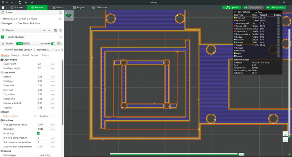
So the one path thick flex part is securly bonded to the rest of the geometry.
You can have an influence on this parameter by editing the seam position in Bambu studio.
On my final project page you can download the G-codes to print the reliant mechanisms on a bambu printer.
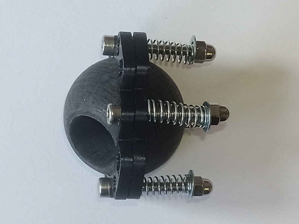
Further, I designed a planitary holder for a green laser to adjust the laser beam to the middle of the reliant mechanism.
The two holder, which hold the ball in the middle in place, are fixed with 4 screws and springs, which allow to rotate the laser in the holder.
I used a RP2040-Zero microcontroller, because I needed several pins and wanted to fit the pcbs to the size of the cubes with 48x48 mm.
This was not the best choise, because many Arduino libraries are not compatible to this microcontroller.
Especially, I had trouble with the libraries to connect the Oled display.
So I had to try out several libraries to get things to work (see Arduino code on the final project page).
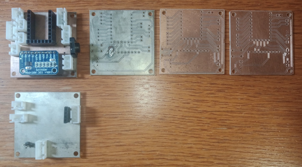
Beside from the µC the pcb contain an analog digital converter, a down converter to supply the laser with a voltage of 3V, a USB conector to power the µC, the stepper motors and the laser, a display to show the readings of the photosensor and several pins to connect everything.
Then I milled the pcbs with our LPKF-mill.
I had to mill the pcbs several times, because some changes had to be done.
In the following image you see the development of the pcb design for my final project.
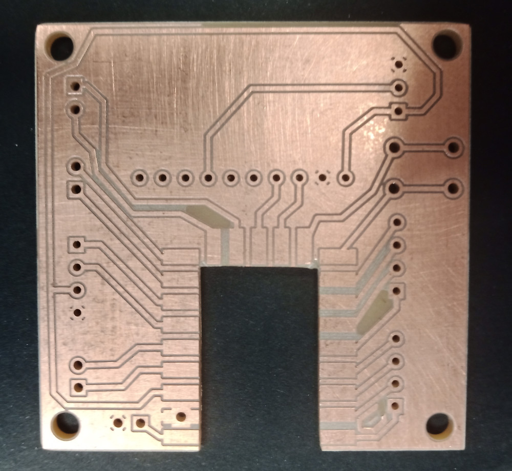
First, I wanted to improve the wire connections, so I alligned them all at the edges of the pcb.
At the first try the connectors were to close together.
The final change I had to do to adjust the design, so that the µC could be surface mounted.
The second pcb I also milled a second time to improve the connection of the wires.
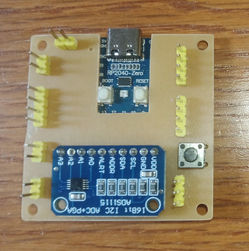
The following image shows the final main pcb with the surface mounted RP2040-Zero.
Here you see both pcbs mounted from top:
And from the bottom:
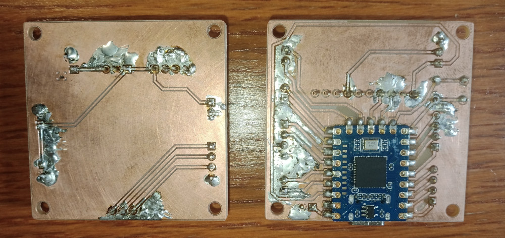
I should have milled a total rubout instead of a partial rubout, then the soldering would have been a lot easier!
With the usage of the flux called "Löthonig" I could prevent shorts in my circuits, but the result looks a bit messy.
Then I wrote the code in Arduino for the stepper motors, the sensor and the display.