15. Interface and Application Programming
assignment
   individual assignment:
      write an application that interfaces a user with an
         input &/or output device that you made
   group assignment:
      compare as many tool options as possible
individual assignment:
This week I programmed an App to control a RGB-Led and Power-Leds.
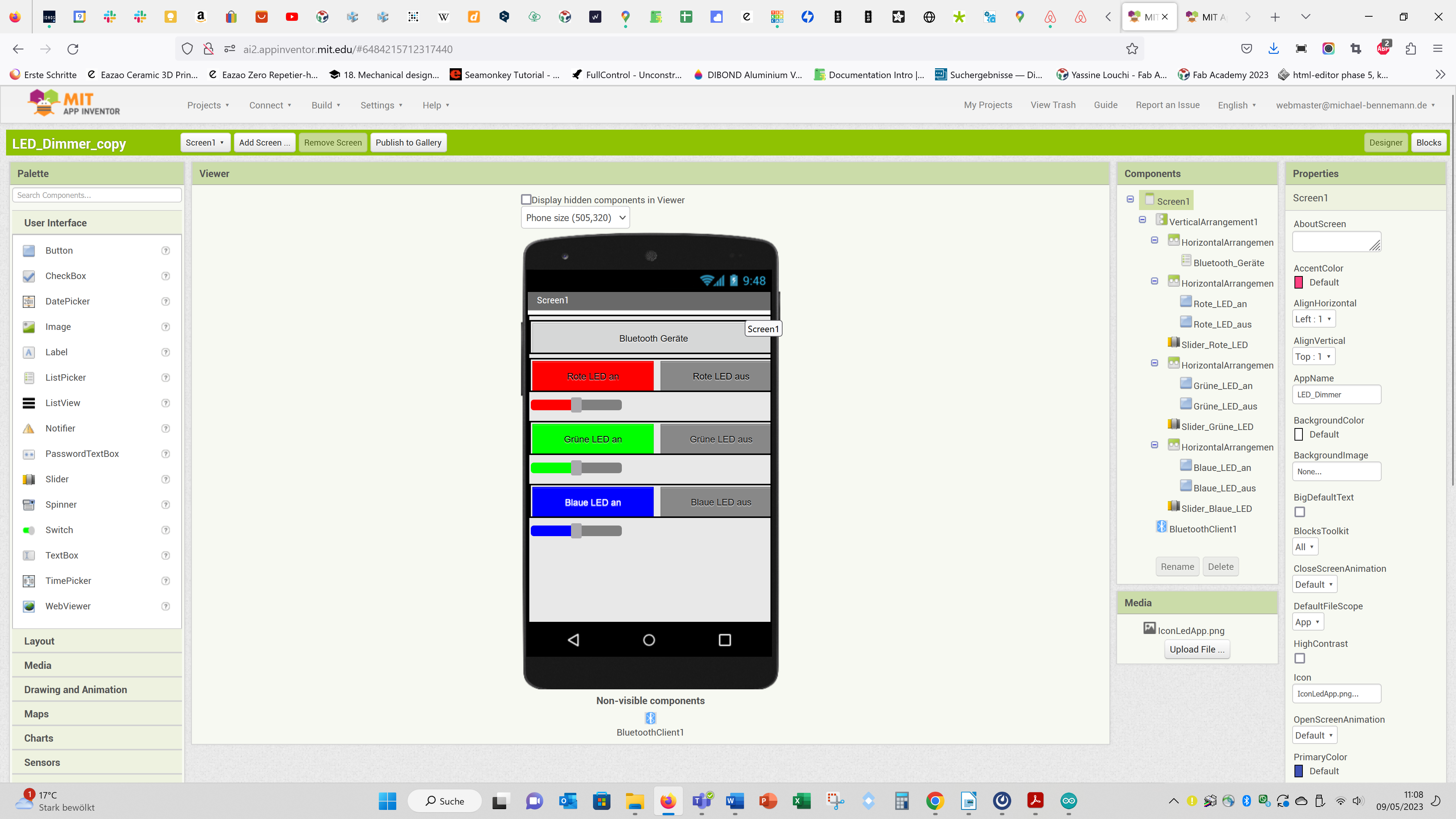
For programming the App I used the MIT App inventor:
On top of the screen I added a button to show and connect to the available Bluetooth devices.
And below I added buttons and sliders for each colour of the RGB-Led.
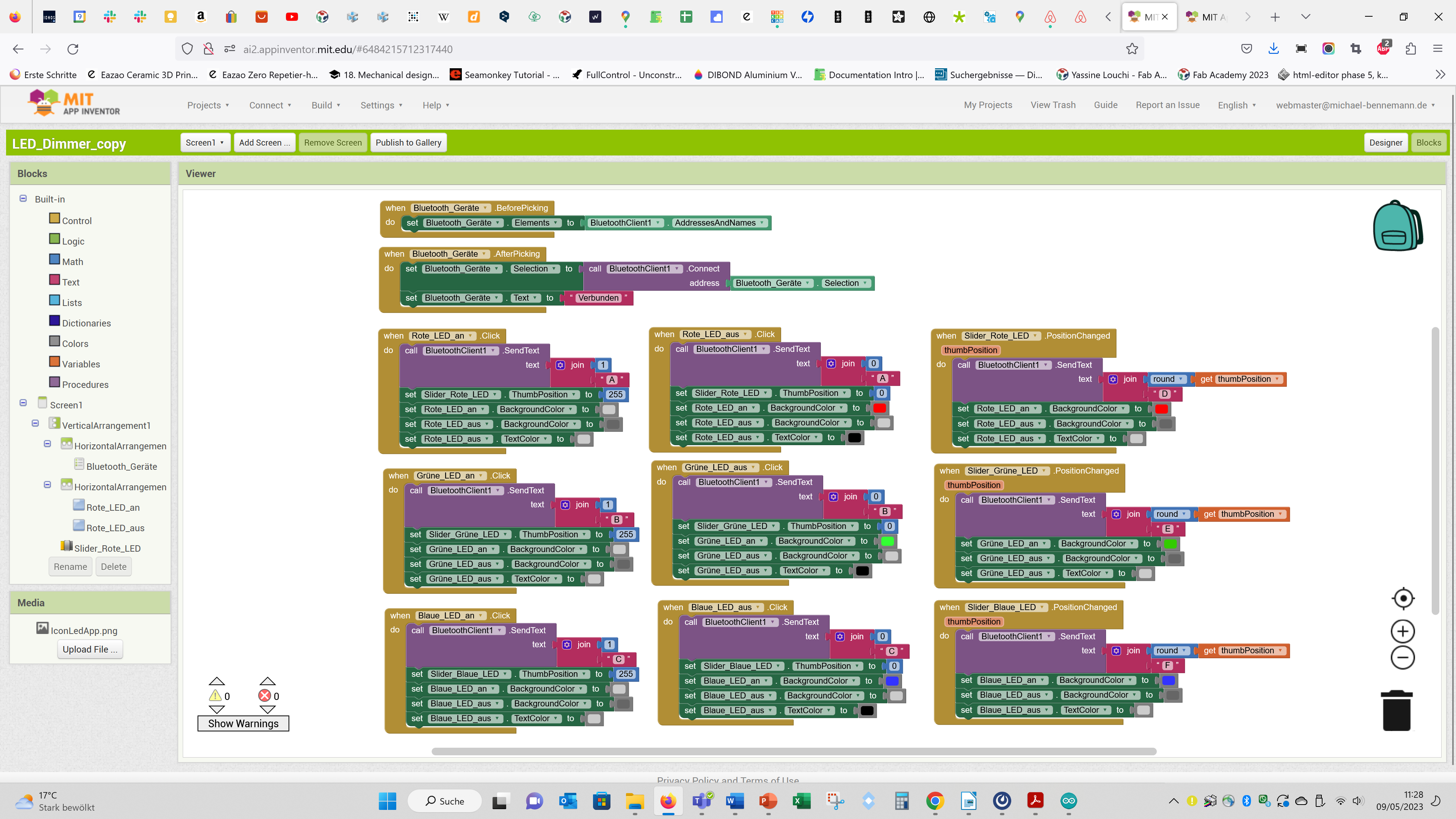
Then I programmed the App using the Blocks. Use the button in the top right corner to change between Designer and Blocks.
Finally I put together an Arduino Code for an Esp32:
// Bluetooth Part von Beispiel Code "SerialToSerialBL"
//This example code is in the Public Domain (or CC0 licensed, at your option.)
//By Evandro Copercini - 2018
//This example creates a bridge between Serial and Classical Bluetooth (SPP)
//and also demonstrate that SerialBT have the same functionalities of a normal Serial
#include "BluetoothSerial.h"
//#define USE_PIN // Uncomment this to use PIN during pairing. The pin is specified on the line below
// von mir auskommentiert: const char *pin = "1234"; // Change this to more secure PIN.
String device_name = "MicsEPS32_38Pin";
#if !defined(CONFIG_BT_ENABLED) || !defined(CONFIG_BLUEDROID_ENABLED)
#error Bluetooth is not enabled! Please run `make menuconfig` to and enable it
#endif
#if !defined(CONFIG_BT_SPP_ENABLED)
#error Serial Bluetooth not available or not enabled. It is only available for the ESP32 chip.
#endif
BluetoothSerial SerialBT;
// Code für APP:
int incomingValue; //Erstellen einer Variable vom Datentyp Integer
char incomingText; //Erstellen einer Variable vom Datentyp char
const int LED_rot = 5; //Pin 5 wird als Pin der roten LED definiert (indirekt per Konstantsromquelle)
const int LED_gruen = 4; //Pin 4 wird als Pin der grünen LED definiert (indirekt per Konstantsromquelle)
const int LED_blau = 2; //Pin 2 wird als Pin der blauen LED definiert (indirekt per Konstantsromquelle)
void setup() //der folgende Block wird nur einmal zum Start des Arduinos ausgeführt
{
Serial.begin(115200); //Startet die serielle Verbindung und setzt die Datenrate auf 9600 Bit/s
pinMode(LED_rot, OUTPUT); //Pin zum Steuern der roten LED wird als OUTPUT konfiguriert
pinMode(LED_gruen, OUTPUT); //Pin zum Steuern der grünen LED wird als OUTPUT konfiguriert
pinMode(LED_blau, OUTPUT); //Pin zum Steuern der blauen LED wird als OUTPUT konfiguriert
SerialBT.begin(device_name); //Bluetooth device name
Serial.printf("The device with name \"%s\" is started.\nNow you can pair it with Bluetooth!\n", device_name.c_str());
//Serial.printf("The device with name \"%s\" and MAC address %s is started.\nNow you can pair it with Bluetooth!\n", device_name.c_str(), SerialBT.getMacString()); // Use this after the MAC method is implemented
// Pin von mir auskommentiert:
// #ifdef USE_PIN
// SerialBT.setPin(pin);
// Serial.println("Using PIN");
// #endif
}
void loop() //Block der loop-Funktion wird schleifenweise ausgeführt (Endlosschleife)
{
// Serial.available zu SerialBT.available:
// if(Serial.available() > 0) //[8, 16] über RX/TX Pin wird geprüft, ob Daten von dem Bluetooth Modul erhalten werden
//{ //ist dies der Fall, wird der folgende Code-Block ausgeführt
if(SerialBT.available())
{
// hier auch BT hinter Serial hinzugefügt:
incomingValue = SerialBT.parseInt(); //[8, 17] nächste gültige Integer Zahl aus den empfangenen Daten des Bluetooth Moduls...
//...wird in die Variable "IncomingValue" geschrieben
incomingText = SerialBT.read(); //[8] char-Anteil der durch das Bluetooth Moduls empfangene Daten wird in die...
//...Variable "IncomingText" geschrieben
// Serial.write(SerialBT.read()); // schreibe über Bluetooth empfangene Daten in den Seriellen Monitor
switch(incomingText) //switch Funktion prüft, ob der Wert der Variablen "IncomingText" mit den folgenden...
{ //...Fällen ("cases") übereinstimmt und führt die entsprechenden Code-Blöcke aus
case'A': //folgender Code-Block wird ausgeführt, wenn ein 'A' empfangen wurde
{ //'A' wurde gesendet, wenn die RED ON-/RED OFF-Buttons in der App betätigt wurden
if(incomingValue == 1) //wenn die empfangene Zahl in der Variablen "IncomingValue" gleich 1 ist...
{ //...welche bei Drücken des RED ON Buttons in der App gesendet wird...
digitalWrite(LED_rot, HIGH); //...werden 5 V am Pin 10 ausgegeben und führen dazu, dass die Konstantstromquelle...
//...die rote Power LED vollständig mit 700 mA versorgt und damit einschaltet
}
else if(incomingValue == 0) //wenn die empfangene Zahl in der Variablen "IncomingValue" gleich 0 ist...
{ //...welche bei Drücken des RED OFF Buttons in der App gesendet wird...
digitalWrite(LED_rot, LOW); //...werden 0 V am Pin 10 ausgegeben und führen dazu, dass die Konstantstromquelle...
//...die rote Power LED mit 0 mA versorgt und damit ausschaltet
}
break; //signalisiert das Ende des case-Blocks nach Ausführen des Codes darin
}
case 'B': //folgender Code-Block wird ausgeführt, wenn ein 'B' empfangen wurde
{ //'B' wurde gesendet, wenn die GREEN ON-/GREEN OFF-Buttons in der App betätigt wurden
if(incomingValue == 1) //wenn die empfangene Zahl in der Variablen "IncomingValue" gleich 1 ist...
{ //...welche bei Drücken des GREEN ON Buttons in der App gesendet wird...
digitalWrite(LED_gruen, HIGH); //...werden 5 V am Pin 6 ausgegeben und führen dazu, dass die Konstantstromquelle...
//...die grüne Power LED vollständig mit 700 mA versorgt und damit einschaltet
}
else if(incomingValue == 0) //wenn die empfangene Zahl in der Variablen "IncomingValue" gleich 0 ist...
{ //...welche bei Drücken des GREEN OFF Buttons in der App gesendet wird...
digitalWrite(LED_gruen, LOW); //...werden 0 V am Pin 6 ausgegeben und führen dazu, dass die Konstantstromquelle...
//...die grüne Power LED mit 0 mA versorgt und damit ausschaltet
}
break; //signalisiert das Ende des case-Blocks nach Ausführen des Codes darin
}
case 'C': //folgender Code-Block wird ausgeführt, wenn ein 'C' empfangen wurde
{ //'C' wurde gesendet, wenn die BLUE ON-/BLUE OFF-Buttons in der App betätigt wurden
if(incomingValue == 1) //wenn die empfangene Zahl in der Variablen "IncomingValue" gleich 1 ist...
{ //...welche bei Drücken des BLUE ON Buttons in der App gesendet wird...
digitalWrite(LED_blau, HIGH); //...werden 5 V am Pin 5 ausgegeben und führen dazu, dass die Konstantstromquelle...
//...die blaue Power LED vollständig mit 700 mA versorgt und damit einschaltet
}
else if(incomingValue == 0) //wenn die empfangene Zahl in der Variablen "IncomingValue" gleich 0 ist...
{ //...welche bei Drücken des BLUE OFF Buttons in der App gesendet wird...
digitalWrite(LED_blau, LOW); //...werden 0 V am Pin 5 ausgegeben und führen dazu, dass die Konstantstromquelle...
//...die blaue Power LED mit 0 mA versorgt und damit ausschaltet
}
break; //signalisiert das Ende des case-Blocks nach Ausführen des Codes darin
}
case 'D': //folgender Code-Block wird ausgeführt, wenn ein 'D' empfangen wurde
{
analogWrite(LED_rot, incomingValue); //[8] ein PWM Signal wird an Pin 10, in Höhe der empfangenen Zahl, welche...
//...mittels Schieberegler in der App eingestellt wurde, ausgegeben...
//...und dimmt damit per Konstantstromquelle die rote Power LED
break; //signalisiert das Ende des case-Blocks nach Ausführen des Codes darin
}
case 'E': //folgender Code-Block wird ausgeführt, wenn ein 'E' empfangen wurde
{
analogWrite(LED_gruen, incomingValue); //[8] ein PWM Signal wird an Pin 6, in Höhe der empfangenen Zahl, welche...
//...mittels Schieberegler in der App eingestellt wurde, ausgegeben
//...und dimmt damit per Konstantstromquelle die grüne Power LED
break; //signalisiert das Ende des case-Blocks nach Ausführen des Codes darin
}
case 'F': //folgender Code-Block wird ausgeführt, wenn ein 'F' empfangen wurde
{
analogWrite(LED_blau, incomingValue); //[8] ein PWM Signal wird an Pin 5, in Höhe der empfangenen Zahl, welche...
//...mittels Schieberegler in der App eingestellt wurde, ausgegeben
//...und dimmt damit per Konstantstromquelle die blaue Power LED
break; //signalisiert das Ende des case-Blocks nach Ausführen des Codes darin
}
default: //wenn keiner der, mit Bedingungen verknüpften, Buchstaben, empfangen wurde,...
break; //wird kein Code ausgeführt und die Schleife erneut gestartet
}
}
} //der Zustand der einzelnen LEDs bleibt, wenn keine Änderungen dazu per...
//...App gesendet wurde, gleich und ermöglicht verschiedenste...
//...Farbkombinationen in unterschiedlichen Zyklen der Schleife
Here you see the setup. The Esp32 is connected to a PCB with the RGB-Led and connectors to connect to power leds. In the image only one power led is shown. The driver of the power led can be powered by 5V, so I conneted it to an USB port.
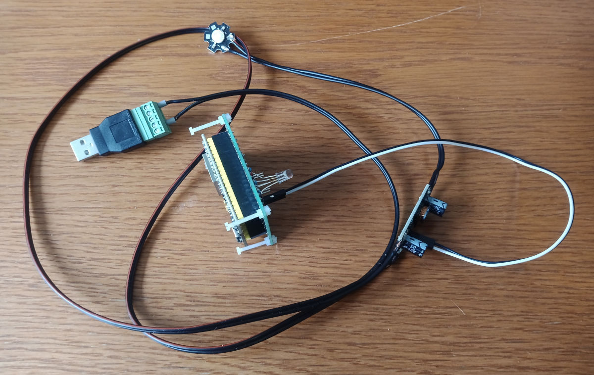
The pin of the RGB-Led for the blue colour is connected to the led driver for 3 Watt leds (the star shaped PCB at the top).
Here you see the device in action. The led driver works apposite to the RGB-Led. Meaning, when PWM is low the power led is on and off if PWM is high:
Further, I controlled the leds on my XiaoEsp32-S3 Board over Wlan:
Here you can download the used code (you have to input your Wlan informations befor upload):
And here you find a good tutorial how to control an Esp32 over Wifi:
https://randomnerdtutorials.com/esp32-web-server-arduino-ide/
group assignment:

For the group assignment I adjusted a code to control the RGB-Led over Wifi using the same set up.

For the code, I used this example as a guide:
https://randomnerdtutorials.com/esp32-web-server-arduino-ide/
I added a third button for the third colour:
/*********
Rui Santos
Complete project details at https://randomnerdtutorials.com
*********/
// Load Wi-Fi library
#include <WiFi.h>
// Replace with your network credentials
const char* ssid = "SSID"; // insert your SSID in the inverted commas
const char* password = "PASSWORD"; // insert your Password in the inverted commas
// Set web server port number to 80
WiFiServer server(80);
// Variable to store the HTTP request
String header;
// Auxiliar variables to store the current output state
String output26State = "off";
String output27State = "off";
String output2State = "off";
// Assign output variables to GPIO pins
const int output26 = 4; // 26 zu 4
const int output27 = 5; // 27 zu 5
const int output2 = 15; // neu
// Current time
unsigned long currentTime = millis();
// Previous time
unsigned long previousTime = 0;
// Define timeout time in milliseconds (example: 2000ms = 2s)
const long timeoutTime = 2000;
void setup() {
Serial.begin(115200);
// Initialize the output variables as outputs
pinMode(output26, OUTPUT);
pinMode(output27, OUTPUT);
pinMode(output2, OUTPUT);
// Set outputs to LOW
digitalWrite(output2, LOW);
digitalWrite(output26, LOW);
digitalWrite(output27, LOW);
// Connect to Wi-Fi network with SSID and password
Serial.print("Connecting to ");
Serial.println(ssid);
WiFi.begin(ssid, password);
while (WiFi.status() != WL_CONNECTED) {
delay(500);
Serial.print(".");
}
// Print local IP address and start web server
Serial.println("");
Serial.println("WiFi connected.");
Serial.println("IP address: ");
Serial.println(WiFi.localIP());
server.begin();
}
void loop(){
WiFiClient client = server.available(); // Listen for incoming clients
if (client) { // If a new client connects,
currentTime = millis();
previousTime = currentTime;
Serial.println("New Client."); // print a message out in the serial port
String currentLine = ""; // make a String to hold incoming data from the client
while (client.connected() && currentTime - previousTime <= timeoutTime) { // loop while the client's connected
currentTime = millis();
if (client.available()) { // if there's bytes to read from the client,
char c = client.read(); // read a byte, then
Serial.write(c); // print it out the serial monitor
header += c;
if (c == '\n') { // if the byte is a newline character
// if the current line is blank, you got two newline characters in a row.
// that's the end of the client HTTP request, so send a response:
if (currentLine.length() == 0) {
// HTTP headers always start with a response code (e.g. HTTP/1.1 200 OK)
// and a content-type so the client knows what's coming, then a blank line:
client.println("HTTP/1.1 200 OK");
client.println("Content-type:text/html");
client.println("Connection: close");
client.println();
// turns the GPIOs on and off
if (header.indexOf("GET /26/on") >= 0) {
Serial.println("GPIO 26 on");
output26State = "on";
digitalWrite(output26, HIGH);
} else if (header.indexOf("GET /26/off") >= 0) {
Serial.println("GPIO 26 off");
output26State = "off";
digitalWrite(output26, LOW);
} else if (header.indexOf("GET /27/on") >= 0) {
Serial.println("GPIO 27 on");
output27State = "on";
digitalWrite(output27, HIGH);
} else if (header.indexOf("GET /27/off") >= 0) {
Serial.println("GPIO 27 off");
output27State = "off";
digitalWrite(output27, LOW);
// neu:
} else if (header.indexOf("GET /2/on") >= 0) {
Serial.println("GPIO 2 on");
output2State = "on";
digitalWrite(output2, HIGH);
} else if (header.indexOf("GET /2/off") >= 0) {
Serial.println("GPIO 2 off");
output2State = "off";
digitalWrite(output2, LOW);
}
// Display the HTML web page
client.println("<!DOCTYPE html><html>");
client.println("<head><meta name=\"viewport\" content=\"width=device-width, initial-scale=1\">");
client.println("<link rel=\"icon\" href=\"data:,\">");
// CSS to style the on/off buttons
// Feel free to change the background-color and font-size attributes to fit your preferences
client.println("<style>html { font-family: Helvetica; display: inline-block; margin: 0px auto; text-align: center;}");
client.println(".button { background-color: #4CAF50; border: none; color: white; padding: 16px 40px;");
client.println("text-decoration: none; font-size: 30px; margin: 2px; cursor: pointer;}");
client.println(".button2 {background-color: #555555;}</style></head>");
// Web Page Heading
client.println("<body><h1>ESP32 Web Server</h1>");
// Display current state, and ON/OFF buttons for GPIO 26
client.println("<p>GPIO 26 - State " + output26State + "</p>");
// If the output26State is off, it displays the ON button
if (output26State=="off") {
client.println("<p><a href=\"/26/on\"><button class=\"button\">ON</button></a></p>");
} else {
client.println("<p><a href=\"/26/off\"><button class=\"button button2\">OFF</button></a></p>");
}
// Display current state, and ON/OFF buttons for GPIO 27
client.println("<p>GPIO 27 - State " + output27State + "</p>");
// If the output27State is off, it displays the ON button
if (output27State=="off") {
client.println("<p><a href=\"/27/on\"><button class=\"button\">ON</button></a></p>");
} else {
client.println("<p><a href=\"/27/off\"><button class=\"button button2\">OFF</button></a></p>");
}
client.println("</body></html>");
// neu:
// Display current state, and ON/OFF buttons for GPIO 2
client.println("<p>GPIO 2 - State " + output2State + "</p>");
// If the output2State is off, it displays the ON button
if (output2State=="off") {
client.println("<p><a href=\"/2/on\"><button class=\"button\">ON</button></a></p>");
} else {
client.println("<p><a href=\"/2/off\"><button class=\"button button2\">OFF</button></a></p>");
}
client.println("</body></html>");
// The HTTP response ends with another blank line
client.println();
// Break out of the while loop
break;
} else { // if you got a newline, then clear currentLine
currentLine = "";
}
} else if (c != '\r') { // if you got anything else but a carriage return character,
currentLine += c; // add it to the end of the currentLine
}
}
}
// Clear the header variable
header = "";
// Close the connection
client.stop();
Serial.println("Client disconnected.");
Serial.println("");
}
}
Here you see a video of the device in action:
First I took the same pins as for Bluetooth, but the led on pin 2 flickered and did not respond to changes on the webpage. After changing to pin 15 it worked.
Under the following link you find helpful informations which pins of the Esp32 you should use and which you should not use.
https://randomnerdtutorials.com/esp32-pinout-reference-gpios/
Comparison:
Both possibilities to control the RGB-led worked well.
Here is a short general comparison between Bluetooth and Wifi:
Bluetooth:
- less energy necessary
- smaller range
- no password needed (advantage or disadvantage)
Wifi:
- more energy needed
- larger range
- password needed
- usually a router is necessary
I think Wifi modules are more often included in microcontrollers.
The Esp32 has Wifi as well as Bluetooth.
For the control of high power consumers I prefer to use Wifi, because I think its more secure.
For programming I like the MIT App inventor much more than to program html in the Arduino code, because you have a graphical user interface. But you also can write Apps using Wifi with the MIT App inventor, but I did not tried this so far.