14. Networking and Communications
assignment individual assignment: design, build, and connect wired or wireless node(s) with network or bus addresses group assignment: send a message between two projects individual assignment: This week I build a RC-transmitter. The receiver consists of an Arduino mini pro, a NRF24L01 transceiver module, a MPU6050 accelerometer and gyro module, 6 potentiometer and 8 switches. The NRF24L01 module communicates with the Arduino using SPI protocol, while the MPU6050 accelerometer and gyro module uses the I2C protocol. Details about the project can be found under the following link: https://howtomechatronics.com/projects/diy-arduino-rc-transmitter/ The pcb was later adjusted to use an AMS1117 and the code was optimised for debugging.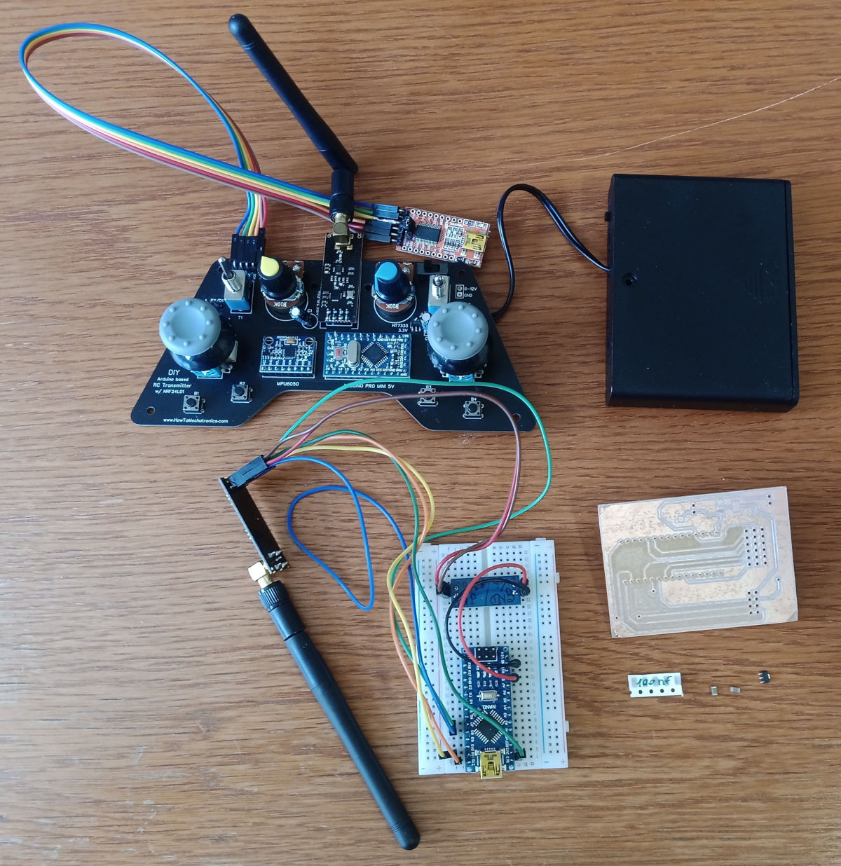
For the assignment we had to connect a self made board with a further node.
I decided to connect the two µC over I2C.
For debugging I first tried to connect two Arduino Unos over I2C:
The Master asks for valus meausred from a photosensor.
If the voltage of the photosensor is above 3 volt the Led on the Master Arduino is on.Here you find the code for the Master Arduino:
#include <Wire.h> #define SLAVE_ADDR 9 void setup() { // put your setup code here, to run once: Wire.begin(); Serial.begin(9600); pinMode(13, OUTPUT); } void loop() { // put your main code here, to run repeatedly: Wire.requestFrom(SLAVE_ADDR, 1); //8: adress of Attiny85, 1: 1 byte of information int d = Wire.read(); //Daten abfragen Serial.println(d); //Daten auf dem Seriellen Monitor ausgeben if(d == 1){ //Wenn byte 1 // if(d == "1"){ digitalWrite(13, HIGH); //LED an }else{ //sonst digitalWrite(13, LOW); //LED aus } }And here you find the code for the Slave Arduino:
#include <Wire.h> int sensorValue = 0; int voltage = 0; #define SLAVE_ADDR 9 void setup() { Serial.begin(9600); Wire.begin(SLAVE_ADDR); Wire.onRequest(requestEvent); pinMode(A0, INPUT); //Photosensor } void loop() { // read the input on analog pin 3: sensorValue = analogRead(A0); // Convert the analog reading (which goes from 0 - 1023) to a voltage (0 - 5V): voltage = sensorValue * (5.0 / 1023.0); // print out the value you read: Serial.println(voltage); delay(500); } void requestEvent() { if(voltage > 3) { Wire.write(1); // Wire.write("1"); } else { Wire.write(0); //Wire.write("0"); } }Then I changed the slave Arduino with my Attiny85 board made in week 8:
The Master Code for the Arduino was the same and here you find the Code for the Attiny:
You have to use the library TinyWire instead of the Wire library.
#include <TinyWire.h> //#include <Wire.h> int sensorValue = 0; int voltage = 0; #define SLAVE_ADDR 9 void setup() { TinyWire.begin(SLAVE_ADDR); TinyWire.onRequest(requestEvent); Serial.begin(9600); pinMode(3, INPUT); //Photosensor } void loop() { // read the input on analog pin 3: sensorValue = analogRead(3); // Convert the analog reading (which goes from 0 - 1023) to a voltage (0 - 5V): voltage = sensorValue * (5.0 / 1023.0); // print out the value you read: Serial.println(voltage); delay(500); } /* void requestEvent() { if(voltage > 3) { Wire.write(1); // Wire.write("1"); } else { Wire.write(0); //Wire.write("0"); } */ void requestEvent() { if(voltage > 3) { TinyWire.send(1); } else { TinyWire.send(0); } }Further, I connected my XiaoRP2040 board with the photosensor to an Arduino Uno. I could use the same codes as used for the two Arduino Unos.
To expand the GND-pins of the Xiao I used a board I made in week 9. I connected both with long male pin headers.
group assignment:For the group assignment we designed a pcb for a RC-receiver (see on the bottom).
The receiver consists of an Arduino nano, a second NRF24L01 transceiver module and an AMS1117.
The transmitter and the receiver can communicate with each other wirelessly over 2.4 GHz.
Unfortunately the AMS1117s did not arrive till now. As soon as they arrive we will solder the PCB.
Details about the project can be found under the following link:
https://howtomechatronics.com/projects/diy-arduino-rc-receiver/