12. Input Devices
      assignment
      individual assignment:
      measure something: add a sensor to a microcontroller board
      that you have designed and read it
      group assignment:
      probe an input device's analog levels and digital signals
individual assignment
For this week, I wanted to measure the intensity of a very low light signal. Therefore, I used the photodiode BPW34.
There are different ways to use a photodiode. Essentially, it is a very small solar cell, and the more light shines on it, the more voltage it produces. However, the voltage does not rise linearly with the amount of light. Not only does the voltage increase with light intensity, but also the current strength, and the current increases linearly. Since the Arduino microcontroller I used can only measure changes in voltage, you have to use a transimpedance amplifier, which will transform the varying current into varying voltage. Because the voltage from the transimpedance amplifier is very low, you need an operational amplifier to increase the voltage. To supply power to an operational amplifier, you need positive and negative voltage. For this, I used a boost converter, which provides positive and negative 5 volts and can be powered by 3.3 volts from a microcontroller.
Here's the link for the boost converter I used: https://de.aliexpress.com/item/1005002068396095.html?spm=a2g0o.order_list.order_list_main.111.67045c5fCzPM28&gatewayAdapt=glo2deu
Since I wanted to measure the intensity of very low light, I further used an analog-to-digital converter. With analog-to-digital converter (ADC), you can convert a voltage to a digital signal, which can be processed by a microcontroller. Microcontrollers already have ADCs, but the ones in Arduinos only have a resolution of 10 bits. Meaning they divide the bandwidth of 0 to 5V into 1024 steps. The ADC I used has a resolution of 16 bits, so the bandwidth is divided into 65,536 steps, giving a much better resolution for small changes in voltage.
Here's the link for the ADC I used: https://www.amazon.de/dp/B07TY3TSBG?ref=ppx_yo2ov_dt_b_product_details&th=1
To analyze the performance of the measuring unit, I placed the photodiode and an LED pointing towards it in a light-tight box. I connected the LED to different very high resistors in the mega-ohm range to get the very low light signals I wanted to measure.
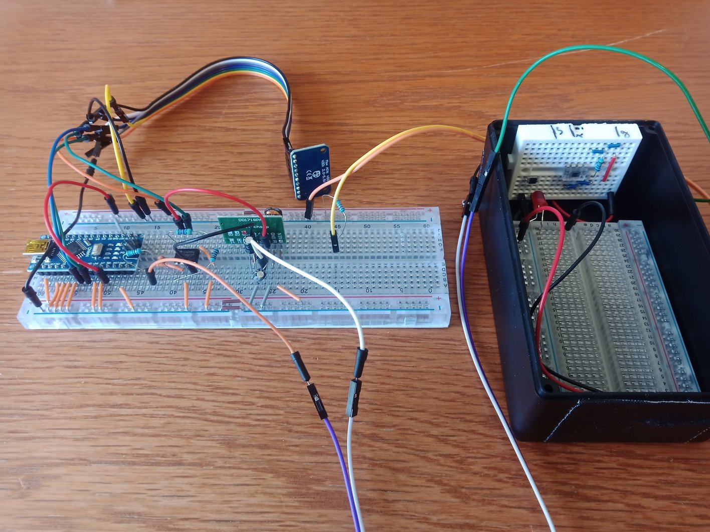
Measuring unit on a breadboard. The black IC is the transimpedance amplifier and the operational amplifier, the green PCB is the boost converter and the blue PCB is the ADC. On the right side, you see the light-tight box.
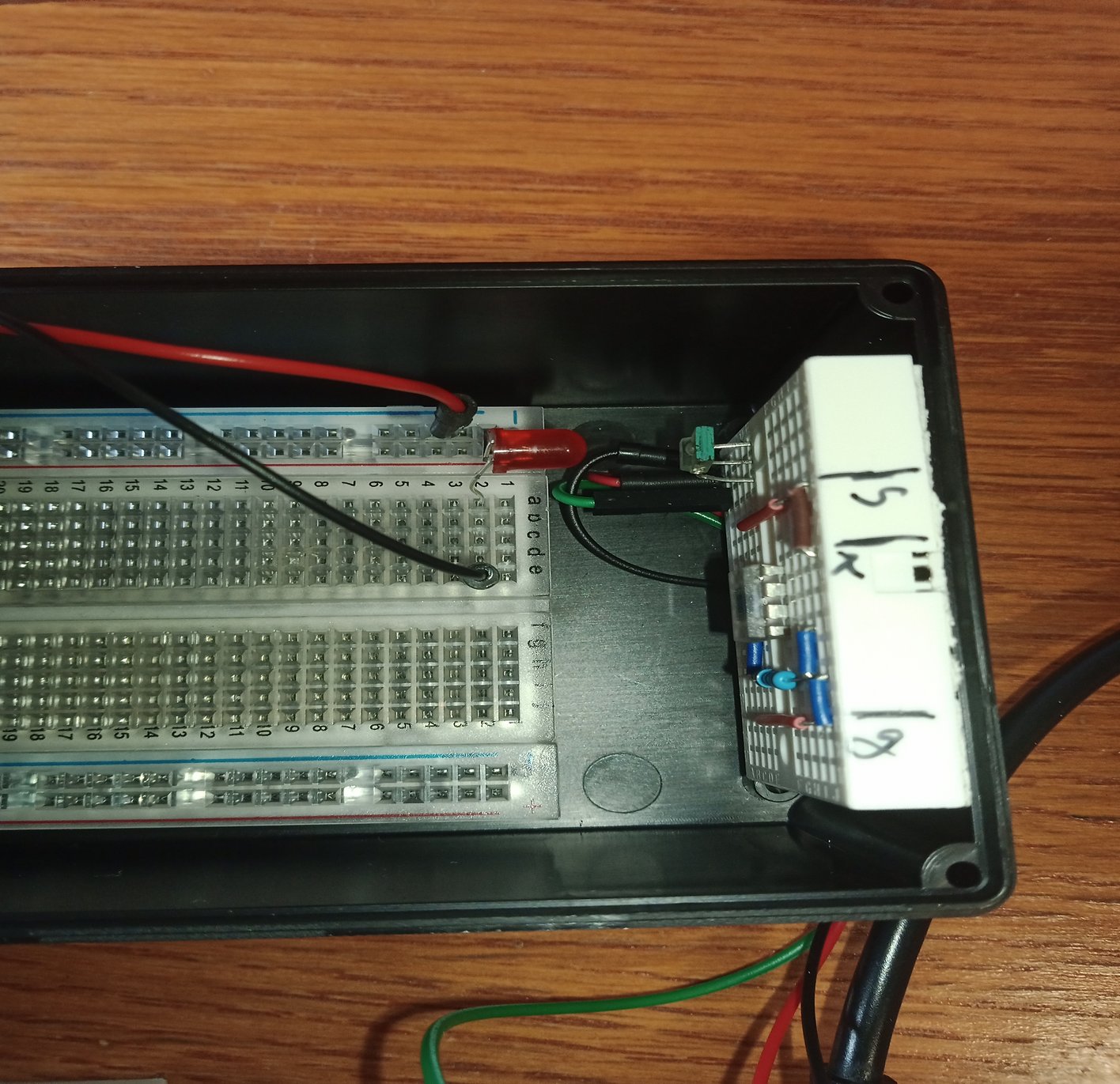
Inside of the light-tight box with the LED and the photodiode (and also a second photodiode I used earlier).
Here are the values I measured for the different resistors (in arbitrary units):
room brightness: -30030
1MOhm: -28200
2MOhm: -28100
3MOhm: -27900
10MOhm: -27800
20MOhm: -27600
darkness: -27300
So I was able to distinguish the light intensity from an LED with a dropping resistor of 10 and 20 mega-ohms and complete darkness. But currently, the measuring unit is very sensitive to everything around it, such as the position of my hand, for example. This sensitivity might be reduced is you place all the electronic components in a metal box, which shall shield it from the surroundings.
Further, I add the photodiode to the microcontroller board I made in week8.
To read the values of the sensor attached to the Attiny85 I used an Arduino Nano as an "FTDI USB to Serial Converter".
First I uploaded the ArduinoISP sketch on the Arduino Nano (see example codes).
Then I attached all necessary wires and an capacitor to programm the Attiny with the Nano and uploaded the code on the Attiny.
After that, I removed the capacitor, uploaded the code "bare minimum" on the Nano (see example codes) and connedted the Rx an Tx Pins of the Attiny to that of the Nano. Then I could see the sensor values (in voltage) in the serial monitor.
A detailed description of the procedure you find here:
https://www.youtube.com/watch?v=9CX4i6rMXS8
I also could have used a FTDI USB to Serial Converter as my instructer did:
https://fabacademy.org/2021/labs/bottrop/students/jonas-vanhagen/src/week10.html
but I wanted to show, that no additional hardware is needed, if you have an Arduino on hand.
Here you find explanations on how to use a FTDI USB to Serial Converter with an Attiny85:
https://www.youtube.com/watch?v=5__0aKdqlDQ&t=122s
https://www.youtube.com/watch?v=1xwWpz2V__4&t=94s
Here you see a video of the sensor attatched to the Attiny85 sending measured data to the serial monitor.
Here you can download the used Arduino code for the Attiny85:
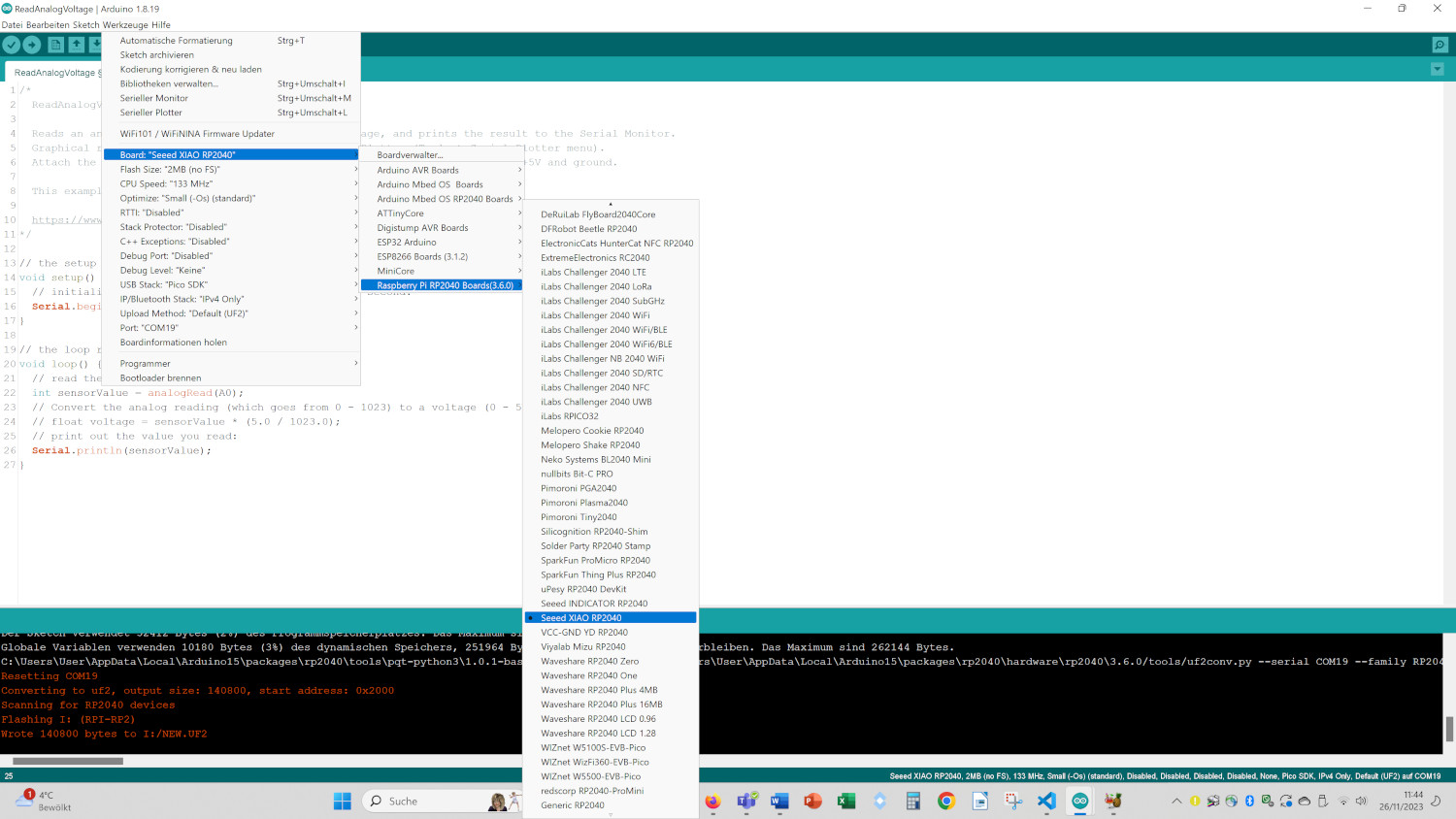
I also connected the photodiode to my XiaoRP2040 board (see week 9).
Here you find a description how to use this board with the Arduino IDE:
https://wiki.seeedstudio.com/XIAO-RP2040-with-Arduino/
After installing the board choose the "Seeed Xiao RP2040" board:
Here you see the values of the sensor plotted on the serial monitor:
I used the Arduino example sketch "ReadAnalogVoltage" without the calculation of the voltage.
group assignment
Before measuring the signal with the Arduino, I measured it with a multimeter:
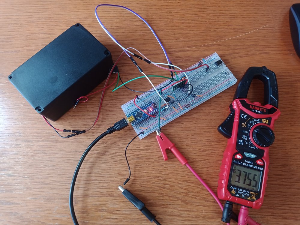
Here are values I measured for different resistors with the multimeter in volts:
68 kOhm 3.76 V
100 kOhm 3.76 V
220 kOhm 3.76 V
1 MOhm 3.45 V
10 MOhm 3.42 V
20 MOhm 3.39 V
darkness 3.36 V
Further analyses you find on the page of Yassine: https://fabacademy.org/2023/labs/bottrop/students/yassine-louchi/index.html