A network is a group of computers/microcontrollers connected between themselves through communication lines. A network can use different protocols to communicate, a protocol is a set of rules agreed between all communication parts and allows them to understand each other and exchange information.
Networks are used to distribute and connect systems (using communication protocols). Networks allow us to connect systems that are lot located in the same place; when we want to do several things at the same time, for example controlling a set of machines in the same network that are doing the same thing at the same time; it also helps to connect modules making systems more scalable and easier to fix and we also use networks to avoid interference between systems, meaning to keep systems protected.
Networks can have different types: ring, star, mesh, fully connected, line, tree and, bus. It also has different ranges such as WAN, RAN, MAN, CAN, LAN, PAN, BAN and, NANO.
Group assignment
For this week's group assignment, we tested the MQTT protocol using our Barduino PCB which has an ESP32 with wifi and the terminal to send messages to our MQTT broker. We started by using Arduino IDE to create a connection to the broker and subscribed to the topics we would want to be listening to, this means we would only receive messages that were being sent to that specific channel. This network communication was very easy to set up since it is wireless and didn't require any wires connection, we only need a wifi connection from Arduino IDE to the MQTT broker (an IP) and then a user and password that allows us to be identified as a client to the broker. There can be multiple clients connected to the broker sending and receiving messages at the same time.
Before designing a network it is important to know that networks can be wired or wireless.
A wired network uses cables to connect the different computers/microcontrollers and there are a few different protocols that can be used: serial (stream their data with a reference signal, one single bit at a time, these interfaces can operate on as little as one wire, usually never more than four), parallel (transfer multiple bits at the same time, usually require buses of data - transmitting across eight, sixteen, or more wires meaning that waves of data can be sent, with high speeds, but with a lot of wires),
Wireless will work using radio frequency waves (through antennas). There are several types of antennas and their size depends on the frequency we want the antenna to be in. Another type of wireless network is the BlueTooth communication, but to use it we can only use communication between peer to peer and the computer/microcontrollers need to be close to each other.
Both, serial and parallel protocols can be synchronous or asynchronous. Asynchronous means that the data is transferred without support from an external clock signal, this is perfect to minimize the required wires/PINs but might not be so reliable (we might be losing data in the communication). Synchronous means that it is paired with a clock signal, so all devices on a synchronous bus share a common clock, this makes usually a faster transfer but more wires.
For this week's assignment, I tested both, a wireless network - using MQTT messaging protocol and a wired network using RX/TX.
Wireless - MQTT messaging protocol
Setting up the MQTT messaging protocol (wireless) in barduino (Fablab Barcelona PCB).
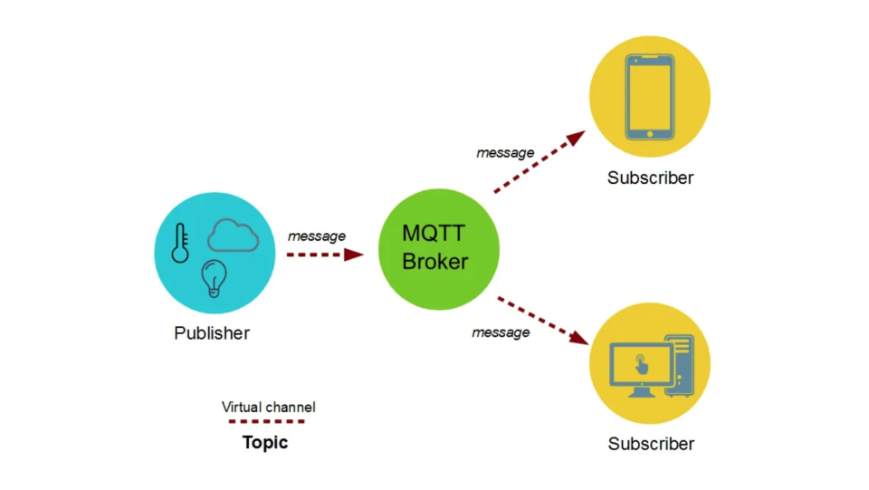
The MQTT messaging protocol
MQTT was designed for limited devices and networks with high latency, low bandwidth, or unreliable networks.
This protocol uses a publish/subscribe architecture that allows messages to be pushed to clients (users subscribed to it).
The managing is made by the MQTT broker - who sends the messages to the respective subscribers of those messages. Clients subscribe to a topic and will only see the messages of that topic, the same for pushing messages, they are being sent under a topic too. The topic is what helps the broker to manage all the messages and who sees them and not. This means that the clients don't need to know each other, so for example multiple clients can be sending messages without knowing who they are.
Using the ESP32 microcontroller from barduino
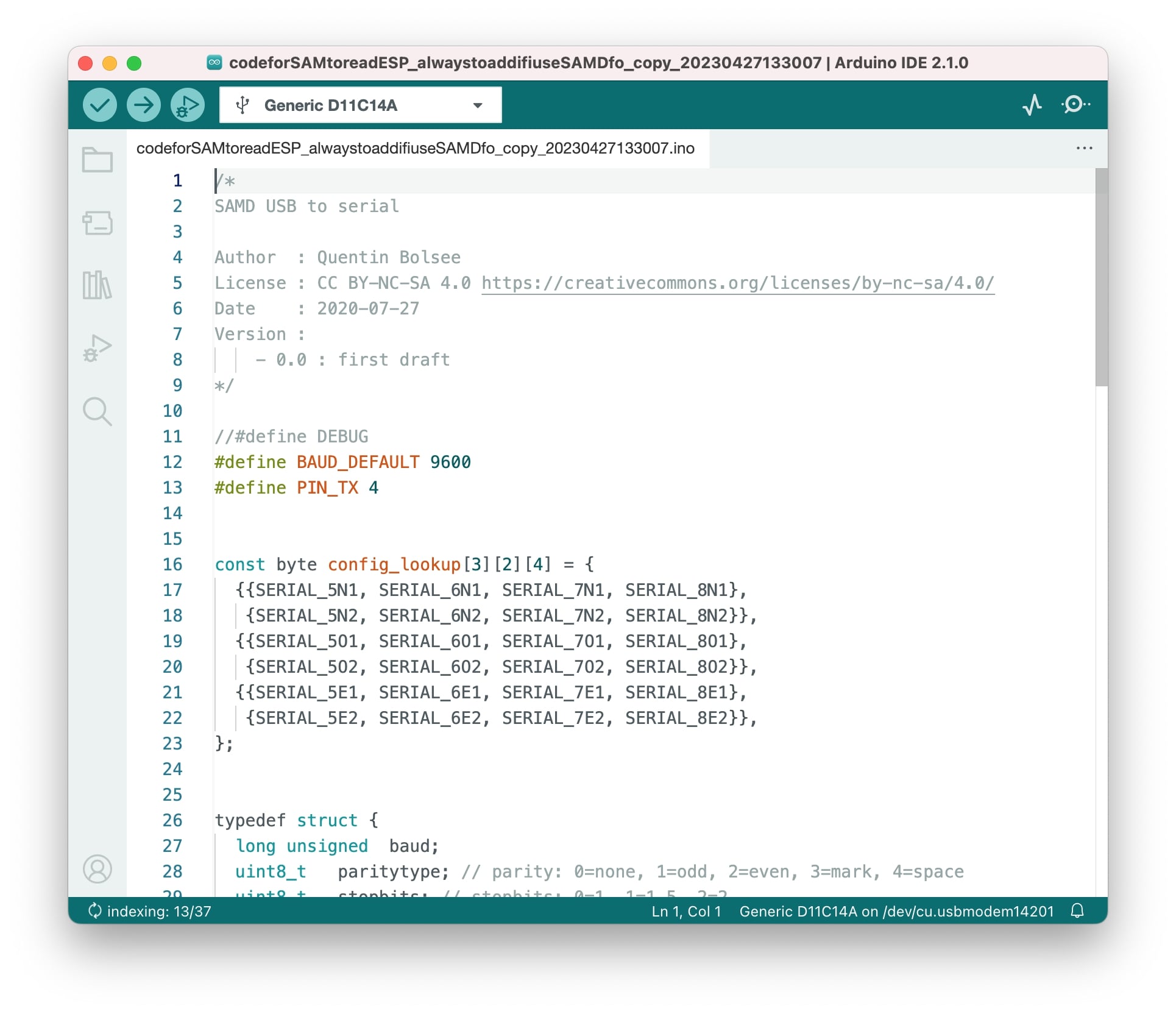
The ESP32 WAROOM DA has embedded a wifi feature that allows to connect it to a wireless network. Before using it I needed to make sure the ESP32 can be accessed by the computer (to add the code to it), since the ESP32 can't directly do that we use the SAMD11 to allow this communication between the computer and the ESP32 (via USB). So I started by adding the code to SAMD11 that allows this (the SAMD11 to communicate to the ESP32).
Connecting to broker
Then it was time to connect the ESP32 to a broker. A broker is the manager of the communications and will receive and distribute the messages to the clients subscribed to it. To use the MQTT protocol (messaging protocol) I installed the PubSubClient library in Arduino IDE. I followed the example given in the class.
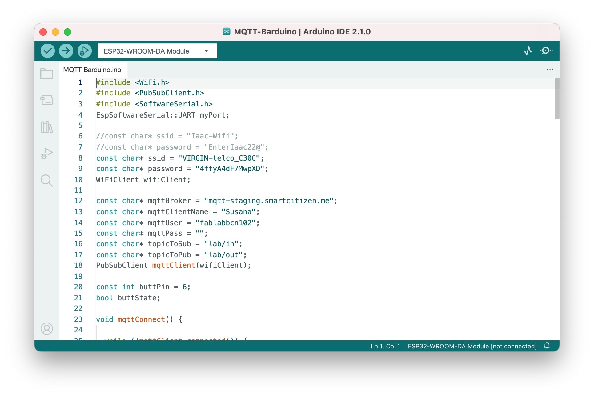
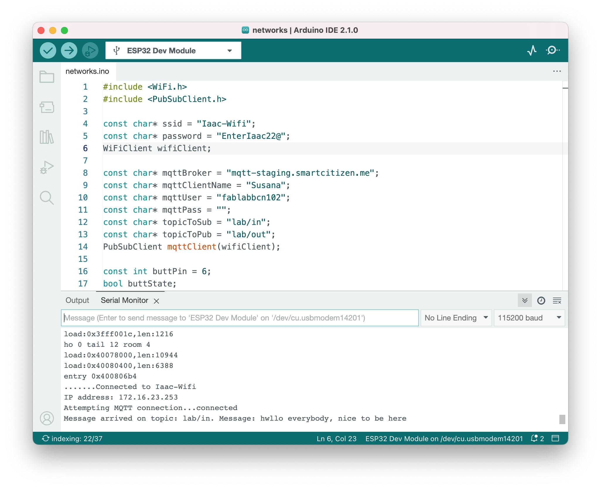
The first thing to do is to declare the libraries at the top of the document (this is the practice for any library we are using). Then I needed to include the wifi connection parameters (user in password). Important to mention that because I also used this at home I had in the code 2 wifi connections, using the one I needed depending on the pace I was. Also in this first part of the code I included the parameters to connect to the broker - IP address, user, password, and topics to be subscribed.
Declaring the functions needed
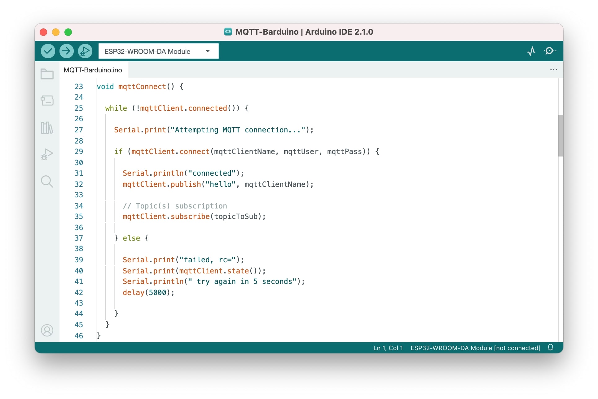
After the connections are set we declare the functions, the first is the mqttConnect() and it's called in the main loop, what is does is that is simply constantly checks is the connection is on and if it is not it will reconnect automatically.
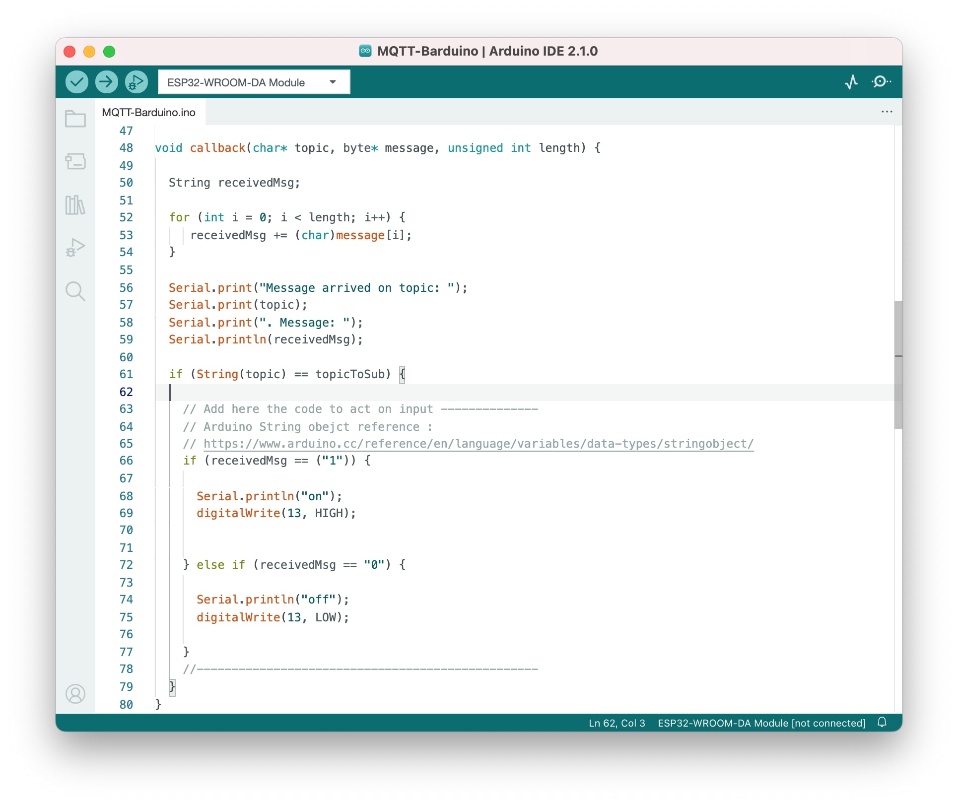
After that function, we declare another callback() that is executed every time a message is received which is checking if we receive new words, if so it turns the LED on (HIGH), and if not the LED is off (LOW).
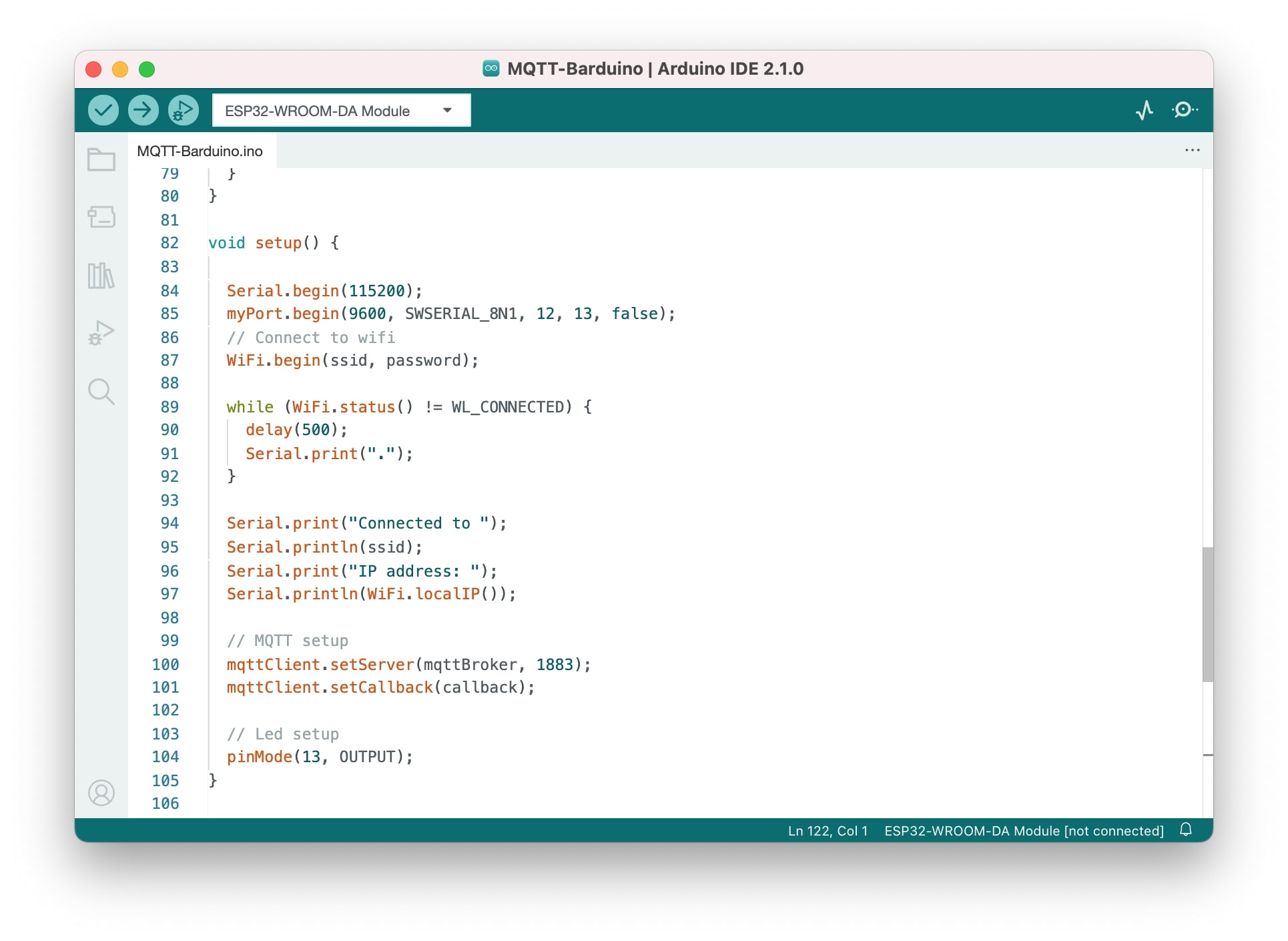
Setup() and loop()
In the setup function, we start the serial communication, wifi, MQTT, and the pin control. The setup function only calls things once. Here we are saying that the serial begins at 115200 so we are sure we get the same message (because we are using the same velocity). We also print in the serial monitor the connection status and the messages.
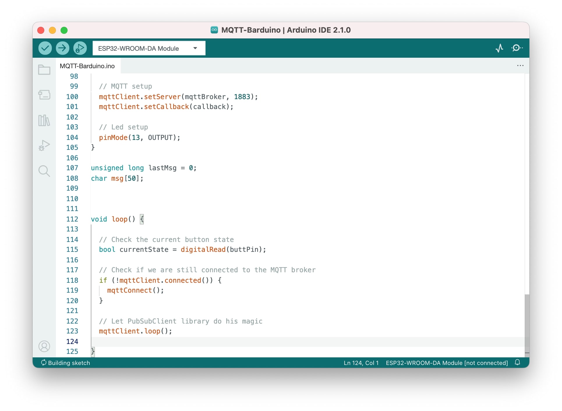
In the loop function, we defined what is being called constantly (in a loop). So we are checking constantly if the connection is on and if there is any new message and if there is we print it.
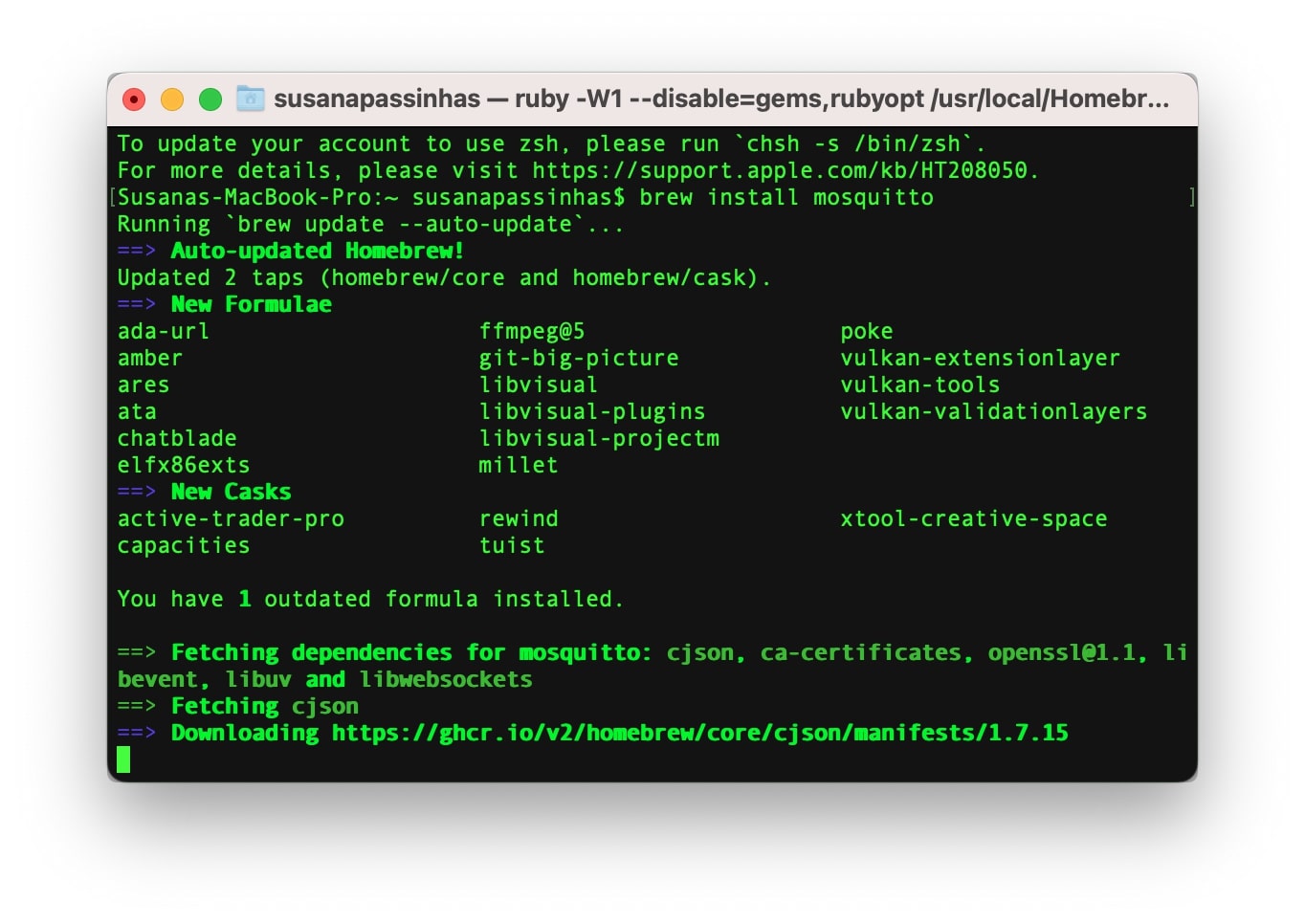
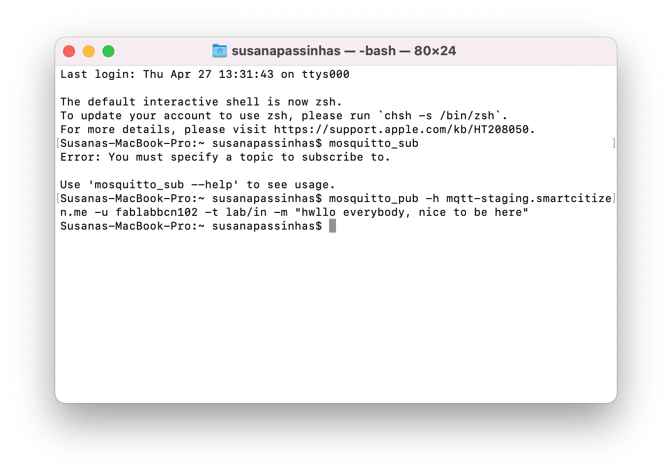
So now that the code was ready we needed to set up the broker and we can do this using the terminal. So I just started by installing the mosquitto using "bre install mosquitto".
Sending a message to the network through the broker
Once it was installed, sending a message is quite simple, we just need to add the IP, user, password, and topic to publish the message.
As soon as the message is sent the ESP32 receives it and is displayed in the serial monitor! In this way as long as the microcontroller has wifi it is easy to have multiple microcontrollers connected in the same network.
Wired - RX/TX serial communication
The RX/TX serial communication
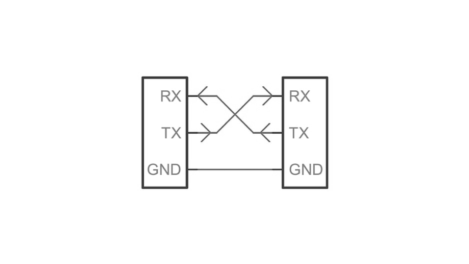
The most well-known asynchronous communication protocol is the RX/TX or simply Serial protocol (because it’s the most important). It requires only two wires, apart from a common ground. Data is sent asynchronously, so it means that both ends of the communication need to agree on some topics, being the speed the most important one (known as baud rate).
When the RX/TX pins are occupied already we can use digital PINs to make them the RX (Receiver)/TX (transmitter) by using the "SoftwareSerial". The SoftwareSerial is an Arduino library that allows serial communication on other digital PINs (that are not the RX/TX).
Connecting ESP32 and Arduino UNO to test
I found a tutorial on how to exhange data between an Arduino and an ESP32 here. It was quite straightforward. I needed to connect the TX and RX from Arduino to the TX and RX of the ESP32 having also a common GND connection. To exchange data between the ESP32 and the Arduino we need to ensure the baud rate is the same.
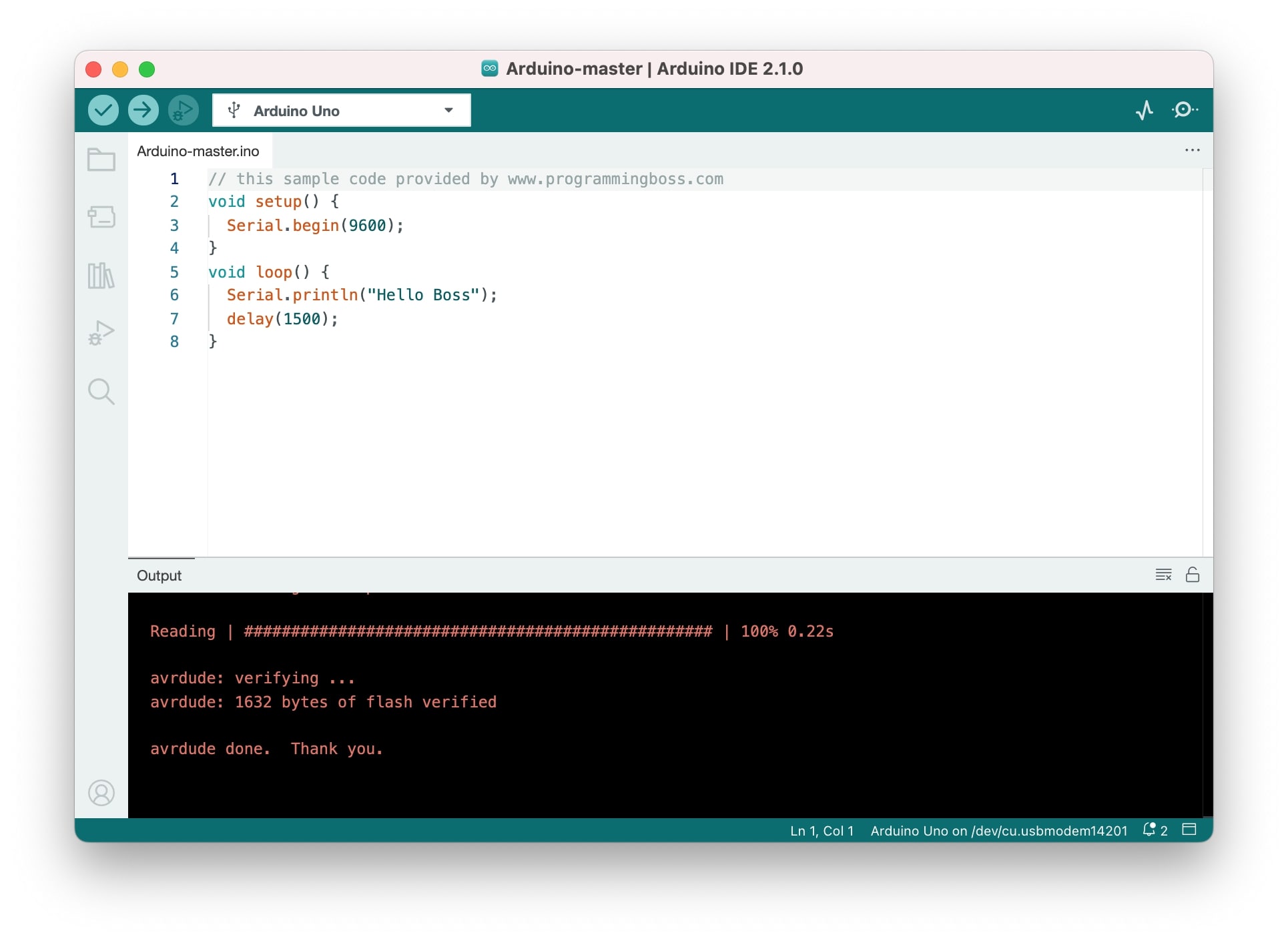
So in the Arduino (Master) we would have this code:
// this sample code provided by www.programmingboss.com
void setup() {
Serial.begin(9600);
}
void loop() {
Serial.println("Hello Boss");
delay(1500);
}
And in the ESP32 (Slave) we would have this code:
// this sample code provided by www.programmingboss.com
#define RXp2 12
#define TXp2 13
void setup() {
// put your setup code here, to run once:
Serial.begin(115200);
Serial2.begin(9600, SERIAL_8N1, RXp2, TXp2);
}
void loop() {
Serial.println("Message Received: ");
Serial.println(Serial2.readString());
}
I was able to make this communication work but I didn't took any screenshot and the next day when I went to connect again...barduino board was not working anymore, my USB port was not being recognized. I guess it was a problem with the SAMD11 because I tried the cable on my own PCB and it worked... So I decided to try this code between Arduino and SAMD11.
Connecting Arduino UNO and SAMD11
Most microcontrollers can transmit and receive data between them using UART communication. So I thought the code above and connections and code would work as well between the Arduino UNO and the SAMD11.
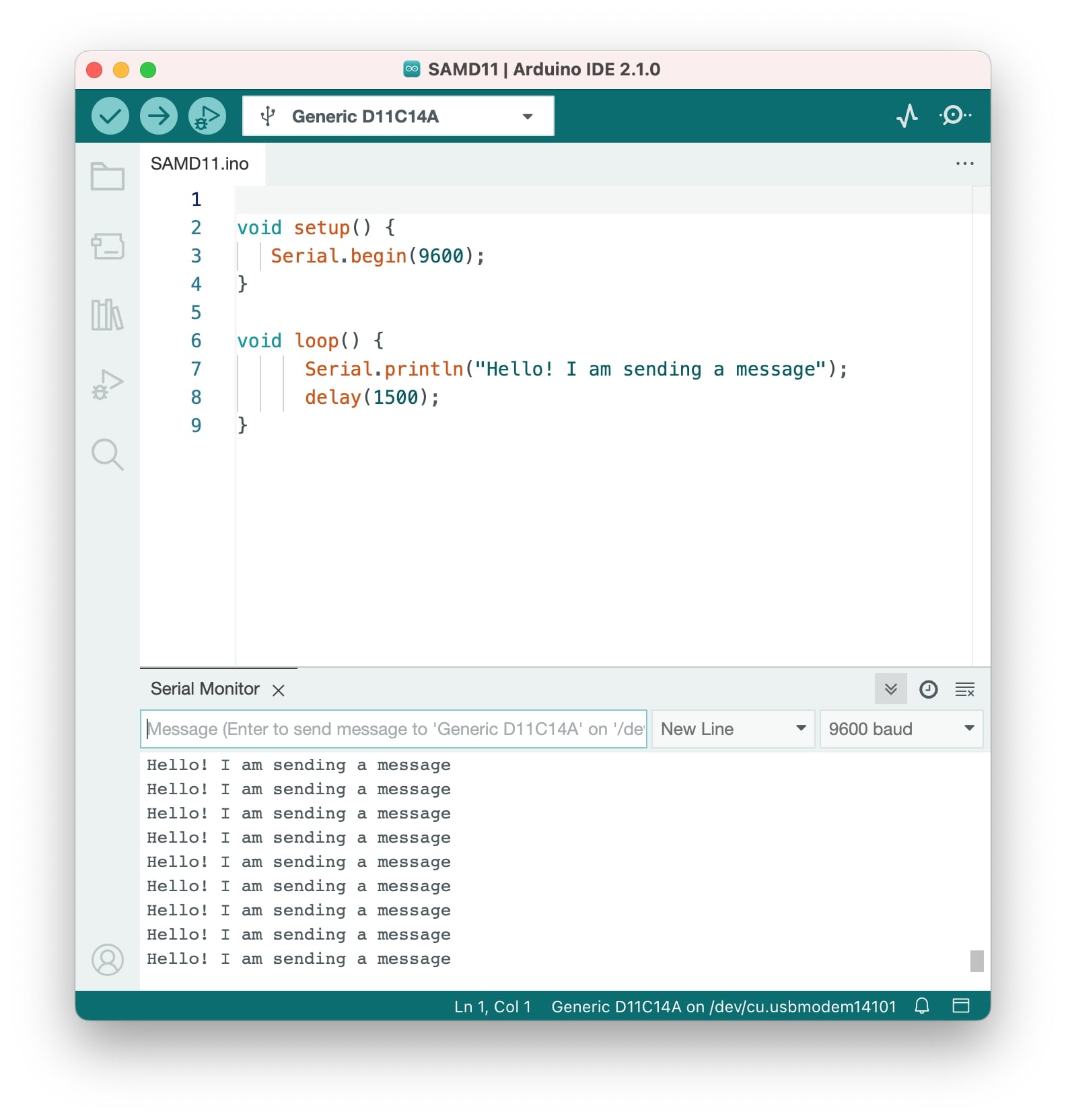
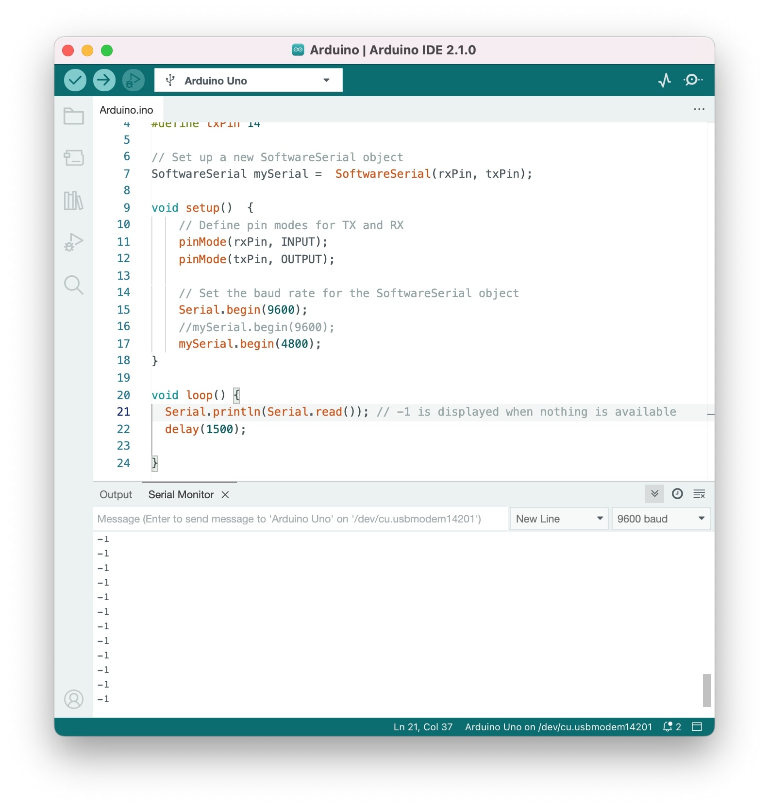
I started by using the SAMD11 as a Master, meaning it was sending a message through a serial port, then in Arduino I created a new serial port that would be reading the serial communication from SAMD11 and printing it in the serial monitor, to do the second serial I needed to use the SoftwareSerial library (allows other PINs to be RX and TX).
So sending the message in SAMD11 didn't seem to be a problem, it is simply printing a string and it works...but in Arduino it was not working so well...Also doing this connection was not quite working as I later came to realizing I was not using the correct PINs of SAMD11!
Connecting Arduino UNO and SAMD11...again
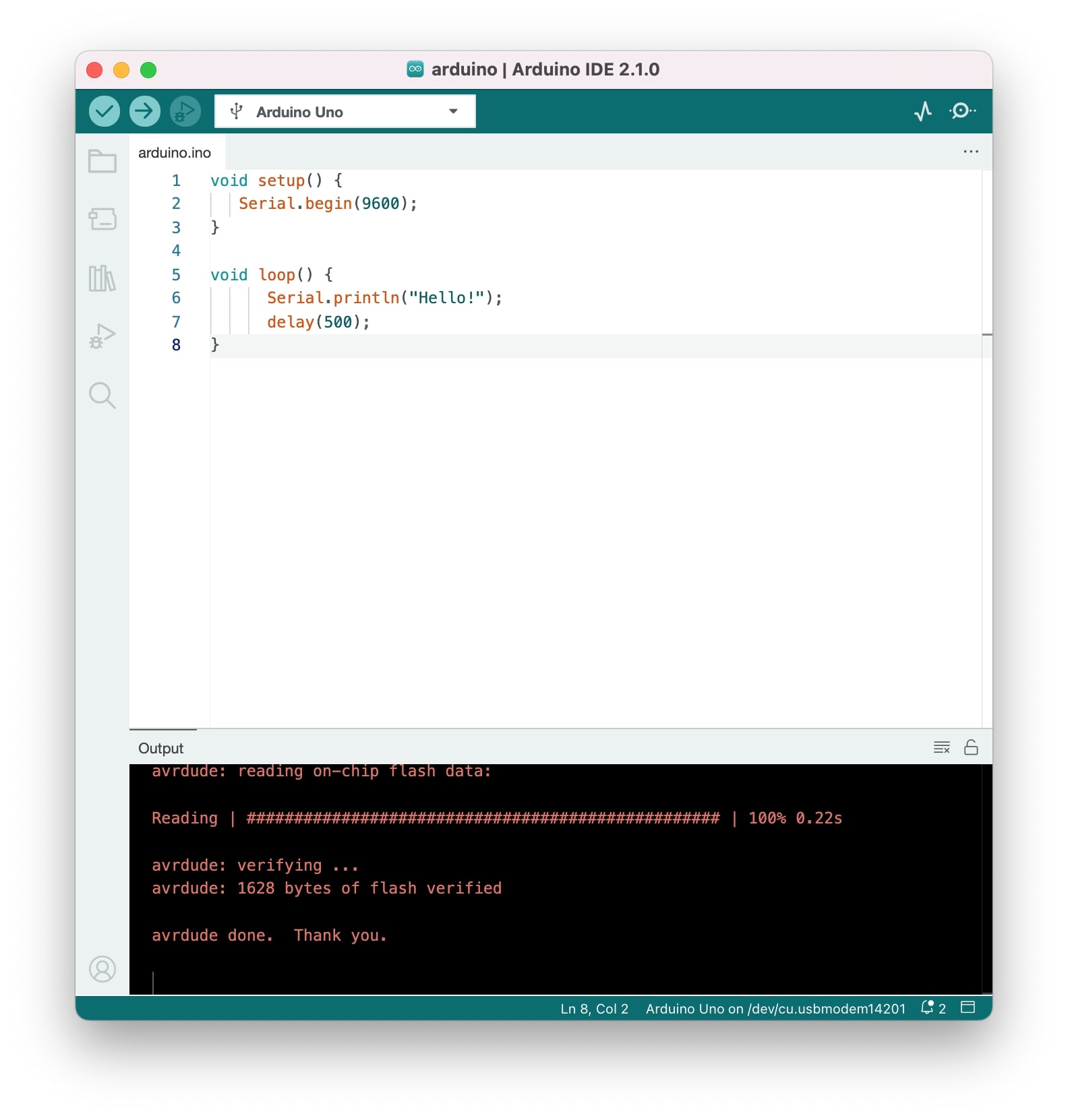
So I shared this code with my instructor and we looked at it together to see what could be the problem. The code of the sender is ok and it works, but we reversed the sender and the receiver, so instead of SAMD11 being the sender it was now the receiver, so I uploaded this code to the Arduino UNO.
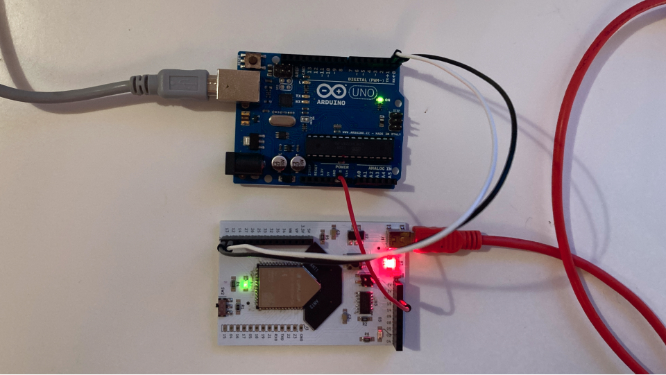
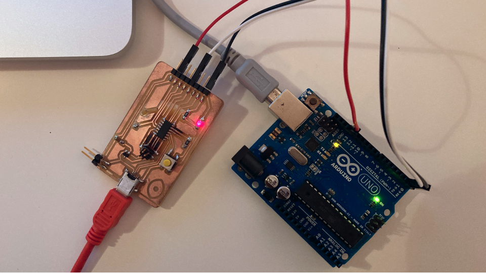
Then it was time to go deeper into the receiver's code. First I realized that SAMD11 doesn't work with the SoftwareSerial library so we checked the SAMD11 datasheet to check which PINs could be used as RX and TX. There were 2 PINs available for TX (30 and 4), and 2 more for RX (31 and 5), because I had exposed the PINs 4 and 5 I worked with those connecting them in reverse with the RX/TX from Arduino, so 5 the RX connected with the TX of Arduino and vice-versa. The same logic is for PIN 4 (you can see these connections clearly in the video below).
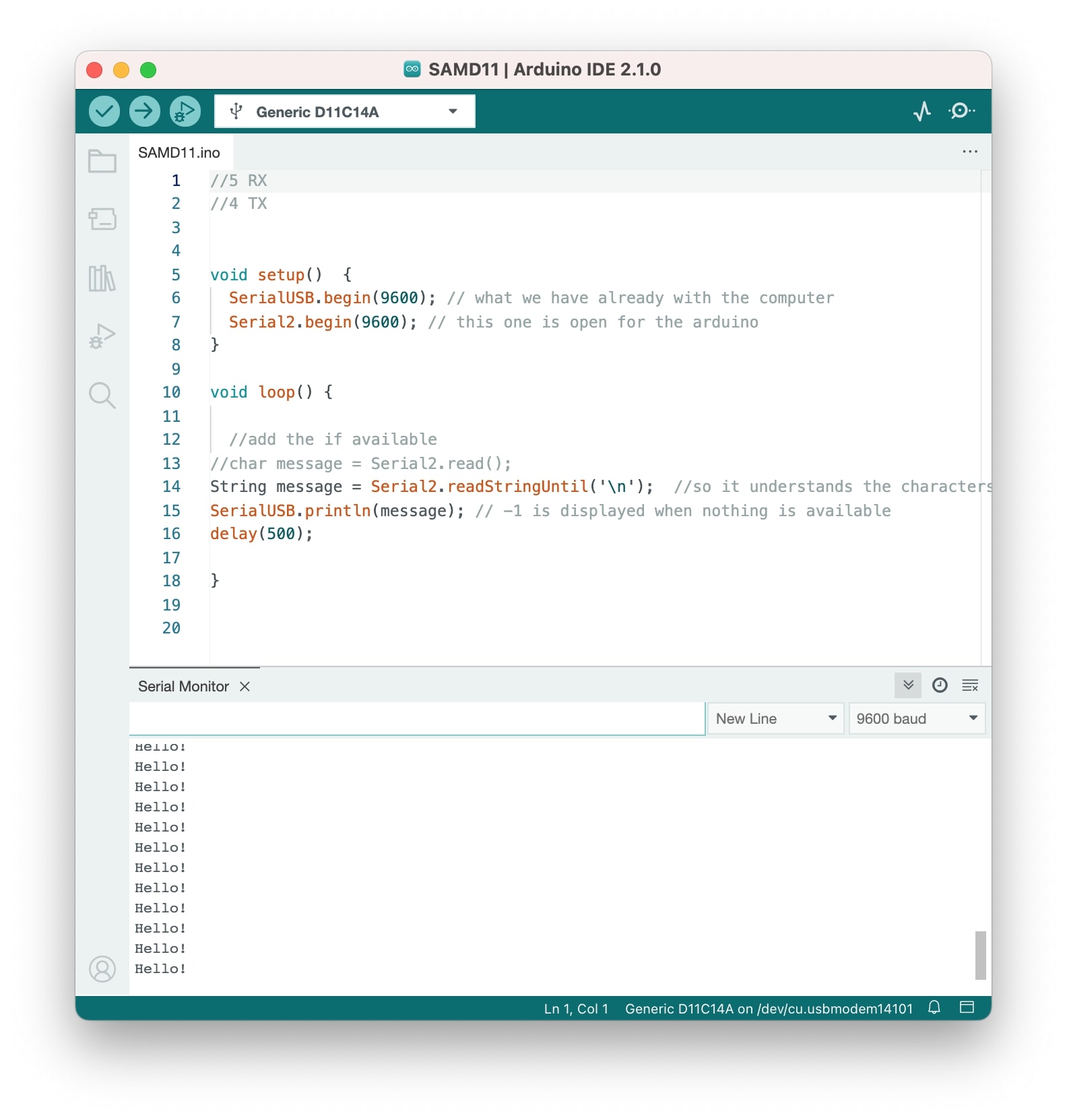
Now in SAMD11 I didn't need to use the SoftwareSerial because I was using the default PINs for the RX/TX communication. So I used the USB Serial connection that the computer already has with the SAMD11 to show in the serial monitor what was happening in the communication between the SAMD11 and the Arduino. I used the same baud rate for my serials so that the velocity would be the same and the message could be "understood". I also added a String to read the message instead of a "char", because the "char" was reading the message as individual characters, with the "String" we read the entire string until there is no string (/n).
And finally the communication was working!
Wired - I2C serial communication
I2C stands for the inter-integrated controller. This is a serial communication protocol that can connect low-speed devices. It is a master-slave communication in which we can connect and control multiple slaves from a single master. In this, each slave device has a specific address.¹
Connecting Arduino UNO and SAMD11...in a I2C serial communication
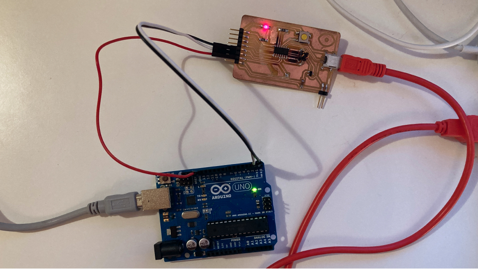
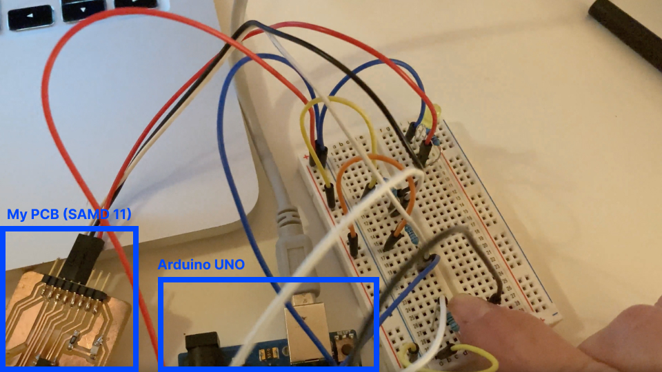
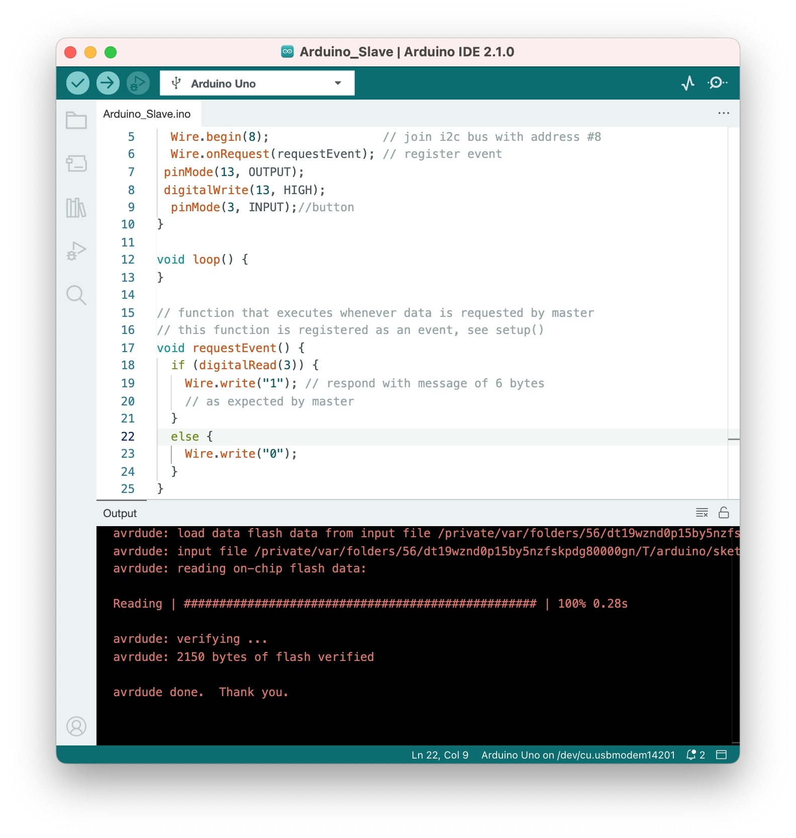
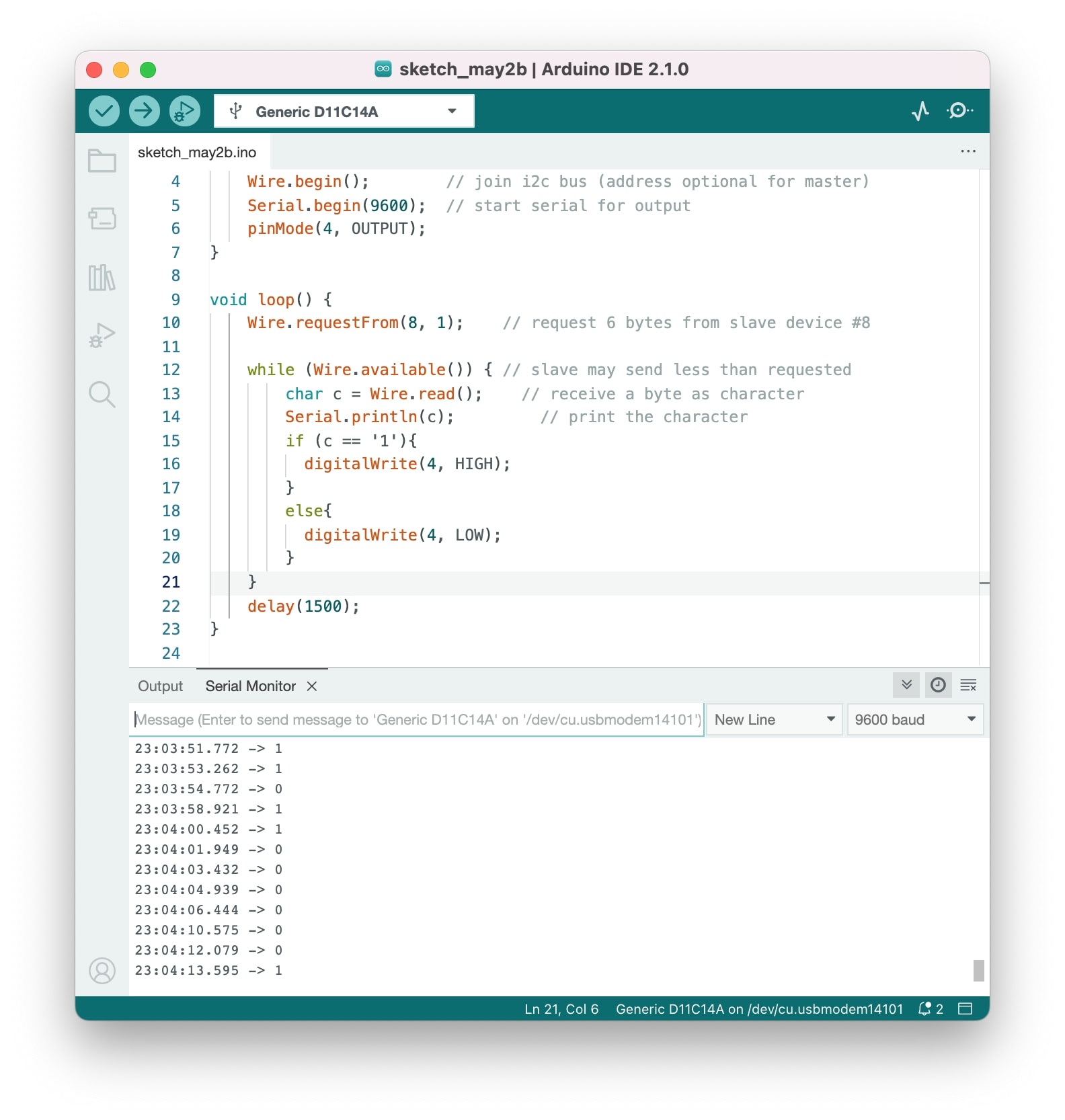
In this case, I connected the SAMD11 (master) and the Arduino (a slave). In this case, the slave is joining with a specific bus address and it's sending a 6 bytes message where it sends a 1 or a 0, depending if a button (INPUT) is being pressed or not. The master (SAMD11) can be in this bus too and it opens a serial so that we can read these messages coming from the bus. In this case, we say in the code that if the slave sends a 1 we light up a LED as an output.
To do this connection I used Arduino instead of the ESP32 and also my LED in the SAMD11 was not working for some reason so I looked up a tutorial on how to connect a button and also a led. I also read a bit more about I2C in Arduino here and I used the example given by the instructor here.
I thought this would be quite an easy week for me, I thought it was quite straight forward, but as usual with code and electronics, it is not...I spent more hours trying to figure out why is not working than in any other week! I also struggled with not having extra boards to test things at home, considering that Monday is a bank holiday I can only use Tuesday to try to figure out why my connection between Arduino and SAMD 11 is not working with the help of the instructors... hopefully it will work! If I had more boards at home with the ESP32 I would have been easier to debug or try different things for sure, so lesson here is to have enough material to experiment things at home!
Final project and networking and communications
I am not really sure if I will need to create a network for my project, but if I do probably it will be a wireless one.