Molding and casting refer to the process of replicating things. We can create molds with the subtractive process (milling) and the additive process (3D printing). If we have a high quantity of copies molding and casting is the best, if we need a few copies or personalized copies, the best option is to 3D print them. Molds can have 1 face or more, depending on the object we are doing. Faces refer to how the mold is put together (a 2-face mold has 2 parts).
Group assignment
This week we learned about the different materials we could use to create molds and cast objects. We talked about silicones and also we took a look into biomaterials. The main difference is that biomaterials can't keep their shape, they usually shrink, so it really depends on the type of project we are doing. Also, biomaterials can be re-used versus silicone which can't.
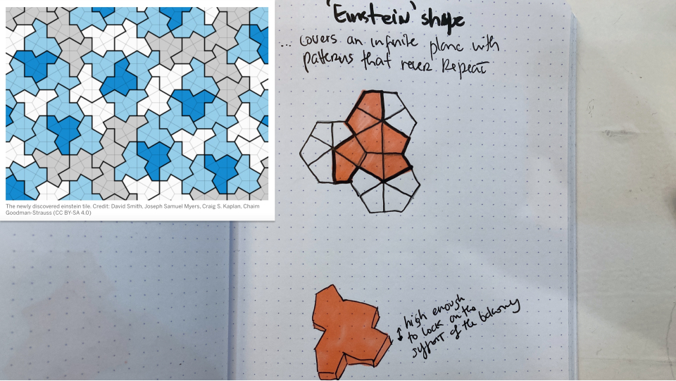
For this week's assignment I wanted to create a tile pattern that I could use in my balcony (I don't have any tiles, it's in concrete), so I thought it would be fun to do it.
The einstein pattern
A while ago I saw this news and I was quite fascinated with it. Mathematicians discovered a pattern that would never repeat and it looks quite beautiful to me (I really love geometric shapes and harsh angles). So I decided to do it as my mold for this week and use concrete to do the tiles. I started by sketching the pattern on paper to understand how it is designed.
Desinging the shape in 2D
So after I figure out how the shape is done it was time to move to 2D software to design it. I thought it would be easy to start with 2D and then just use 3D software to "extrude" it.
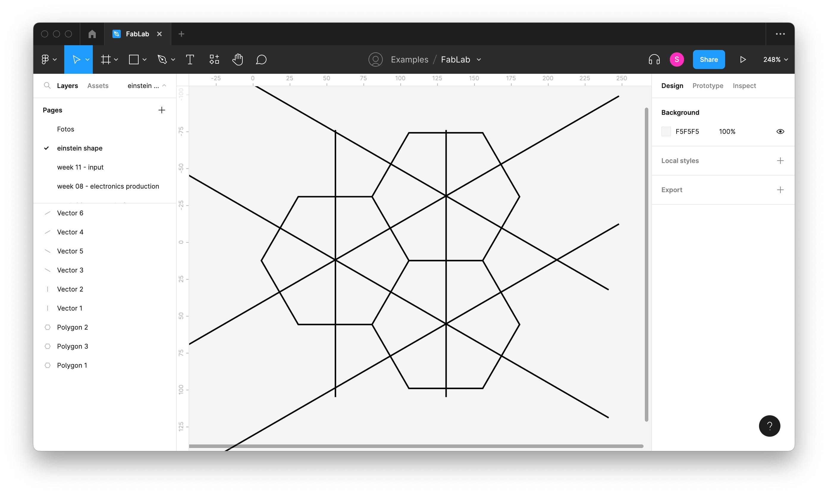
Starting in Figma
My go-to 2D tool is Figma so my first instinct is always to use it, but again I was reminded that this is not a tool for precise/technical sketching/drawing. I started by trying to create the Einstein tile using hexagons and breaking the shape as in my sketches to build the tile...but I figure out this process was not as precise as I wanted and the sizes would not be perfect to the mm so I moved onto LibreCAD.
Installing LibreCAD
LibreCAD is an open-source 2D CAD (computer-aided design) software.
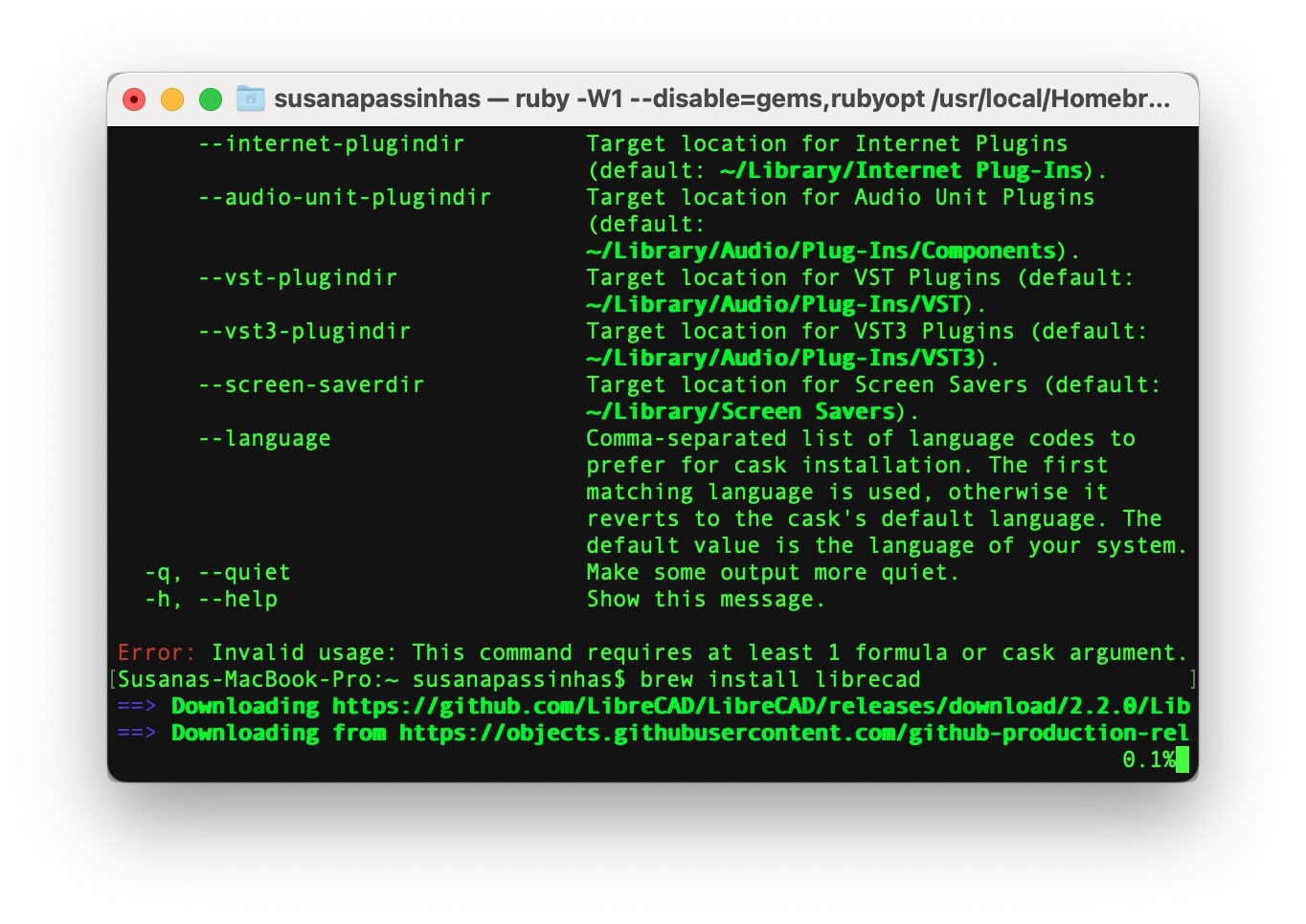
To install LibreCAD I used the terminal. Because LibreCAD has its files on GitHub I could use homebrew to download it. So I just opened the terminal and typed the command "brew install librecad" and that was pretty much it!
Designing in LibreCAD
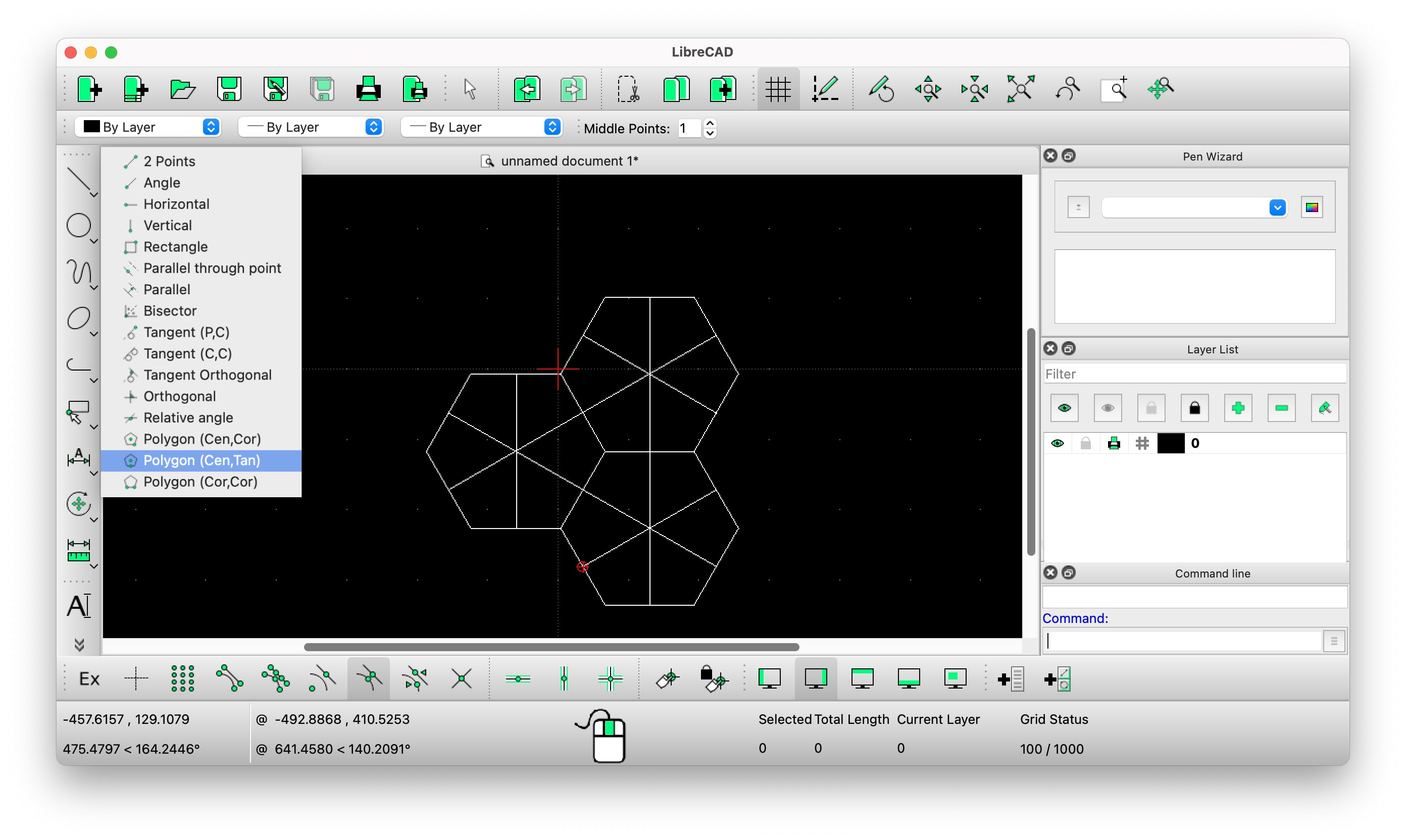
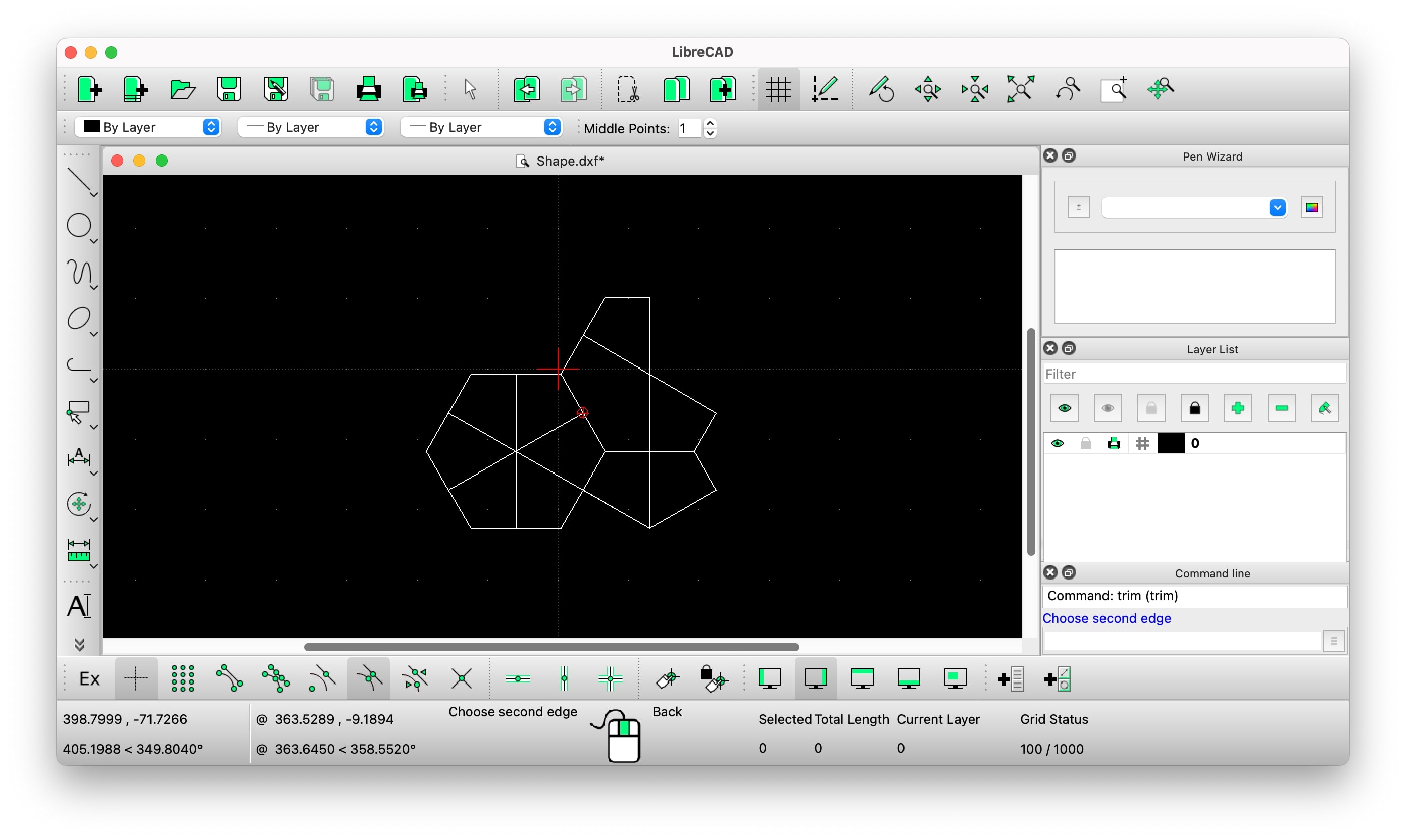
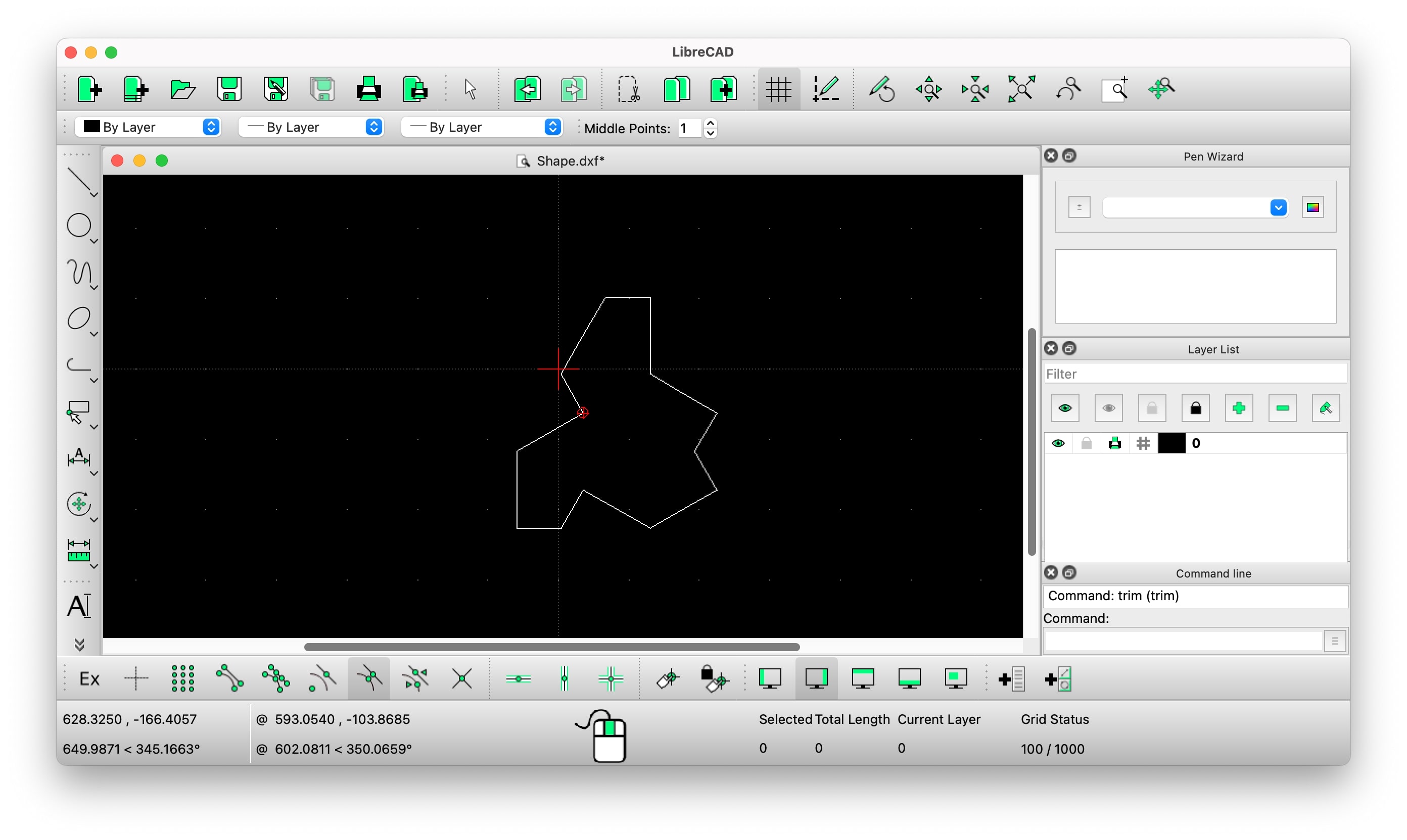
I started by designing a hexagonal shape by clicking the line shape on the panel on the left and choosing "Polygon (Cen, Tan)". I choose this one because I needed to use the center of the edges of the hexagon to build my shape. I also activated on the bottom menu the "snap middle" feature to make sure I am precisely in the middle of each edge of the hexagon when dividing them with a line. Then I went again to the left side panel and clicked the line and then "2 points", so I could draw the divisions on the shape, and after removing the ones I didn't need to get to the final shape.
Once I had my hexagons with the lines precisely in the center of each edge I went to the process of deleting the edges I didn't want, so in the end I get the shape I wanted. To delete the edges I didn't want I used the command "trim" and then selected the edges I wanted to stay - this would remove the ones I didn't want. It was a tryout process as this was a bit hard for me to make sense of at first.
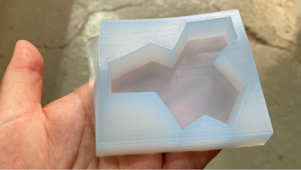
In the end, I got the perfect shape - the Einstein pattern, and was ready to go to the 3D software!
Moving the shape into 3D
Now that my 2D shape was ready, I needed to extrude it in 3D software while making sure that all the walls had a bit of inclination so the mill didn't collide. I also needed to design it inside the wax dimensions.
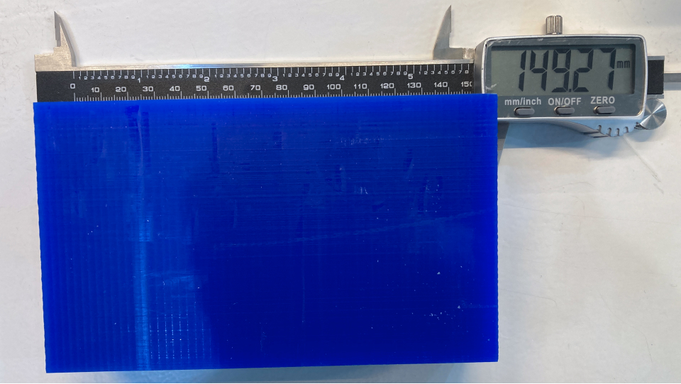
Measuring the wax
Before moving into the 3D software I measured the wax we would be working with (I also realized that my initial goal of doing tiles for my balcony could take a while...). Roughly the measurements were:
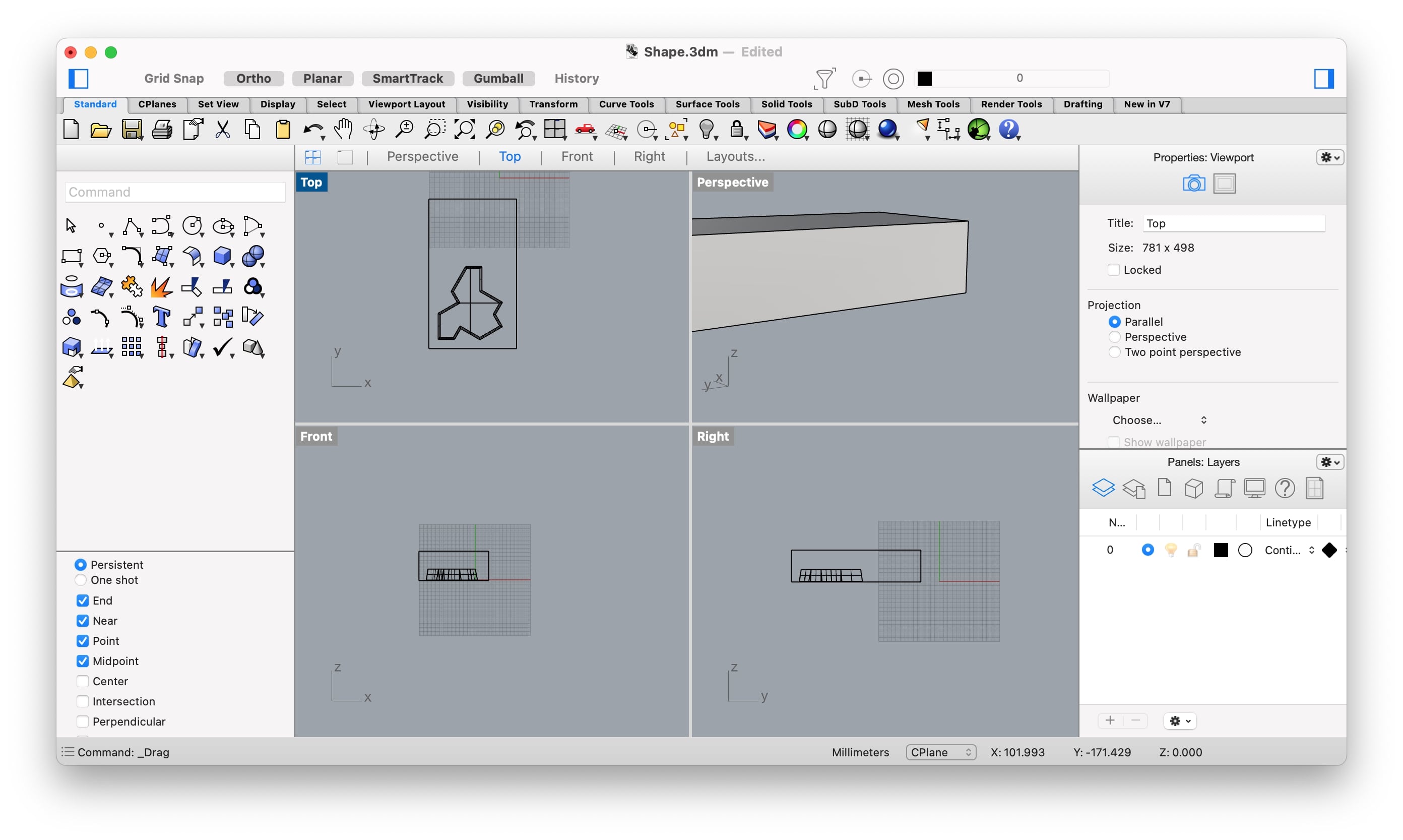
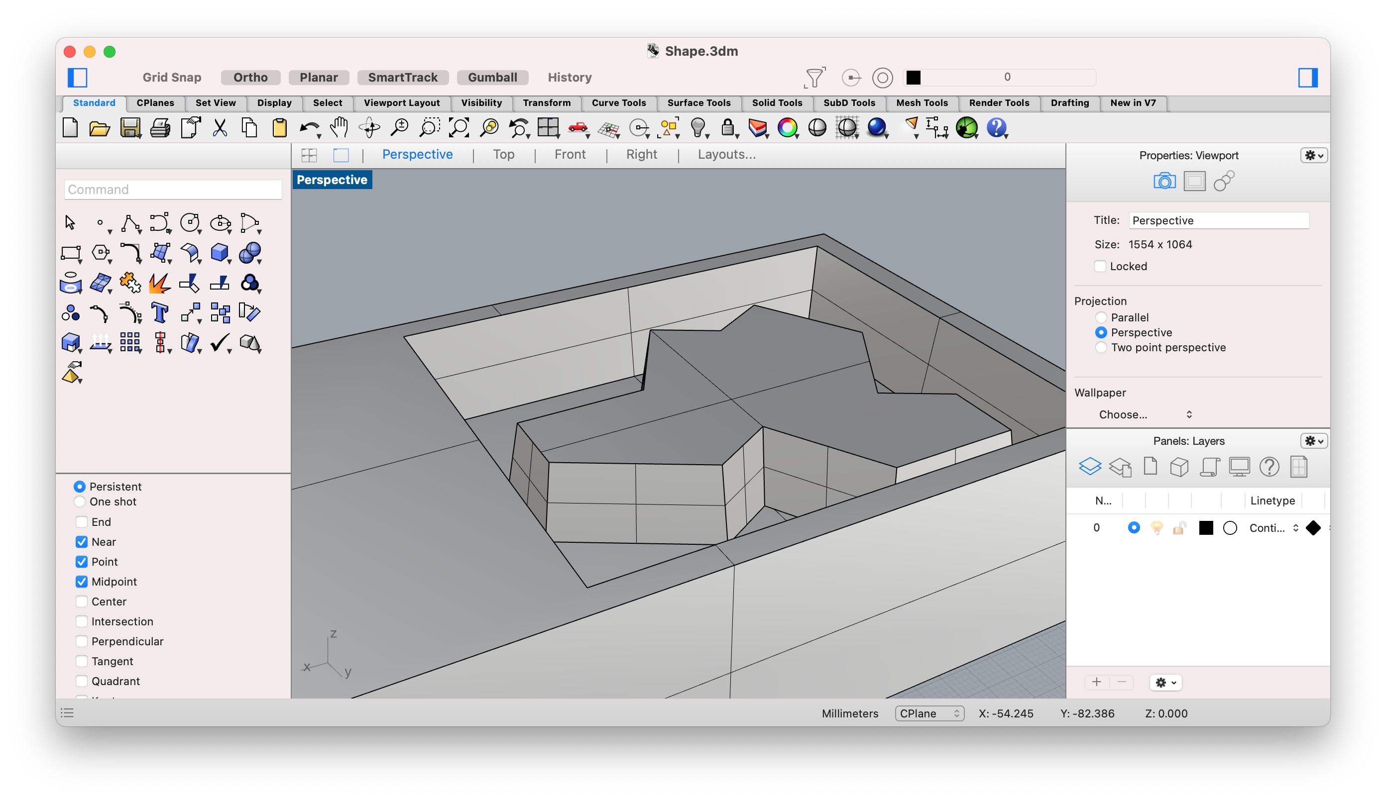
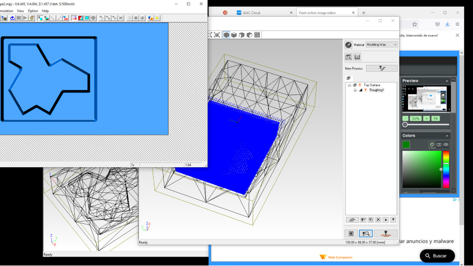
3D modeling in Rhino
I started by opening the DXF file I had saved from LibreCAD. Then I copied it by using copy+paste and then I selected the copied shape and wrote the command "offset" and added 2mm as an offset parameter. This made the copied shape smaller than the first one and would allow the creation of inclined walls when joining both 2D shapes with a face between them. I then moved the copied shape up in the z-axis by 16mm. To join the 2D shapes and create a 3D I used the command "Planar SRF".
After the tile was ready I added a bounding box to it by using the command "BoundingBox" and made sure there was at least 5mm between the wall of the tile and the wall of the wax (I just used a 5mmx5mm cube as a guide), the 5mm is so we make sure the wall of the mold will be good and not break because it is too thin. I also made sure the walls had a 2mm inclination so that the endmill wouldn't collide.
Then I added the rectangle that would be the wax with the measures I had taken before, moved the shape of the tile up, and used a boolean operation to intersect both shapes and I was ready to move on to preparing to the machine.
Preparing for machining
Once the 3D file was ready (STL) I went to the proper software - Modela Player 4, to prepare the file. In this software, we define the tool and the parameters for milling. For milling wax, we need the roughing - that removes the wax and the finishing to smoothen the cut.
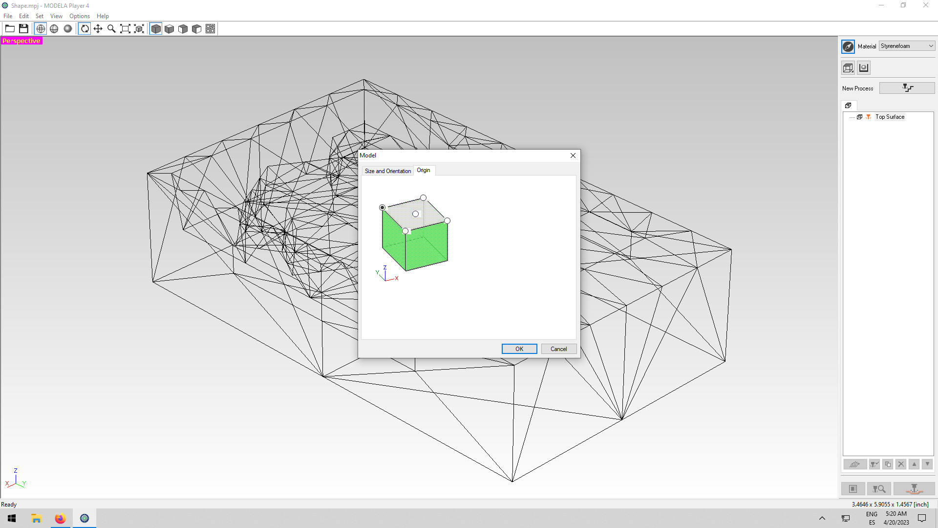
Defining the origin
To start we always need to define the origin so that the 3D model is aligned with our wax object layout in the machine bed. To set the origin I clicked the anchor icon on the right panel and choose the top left corner point.
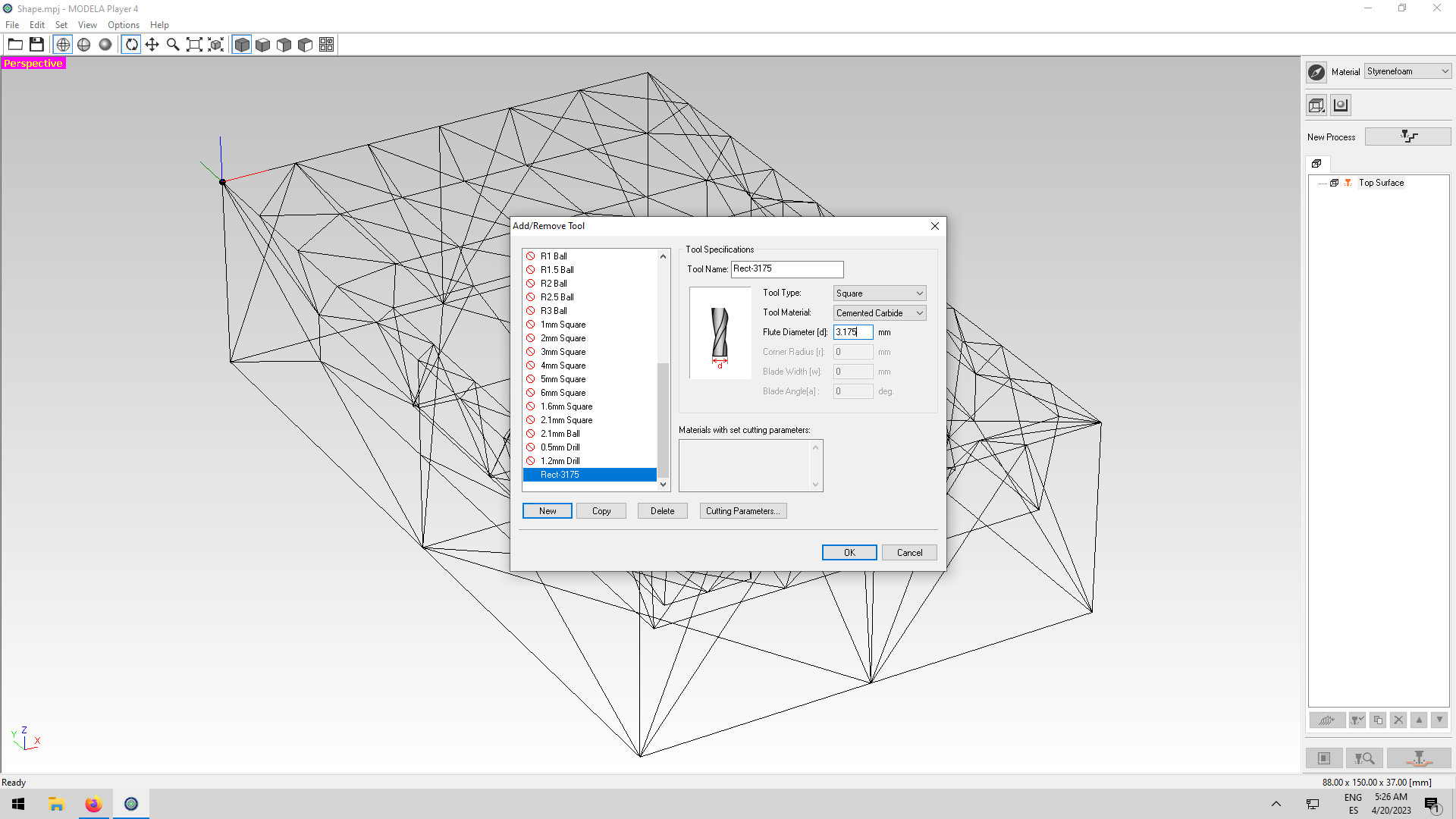
Selecting the machine and adding a new tool
To start preparing the files we start with the "roughing", this is the first process the milling machine will do, but before that, we need to set up the tools and the machine to be used. The machine to be used is the SRM-20 mill, so I set this up in the menu first.
Then before defining the parameters I needed to add the tool (used the top menu "add new tool") I would be using. In this case, I would be using it for roughing the 1/8 endmill (3,175mm).
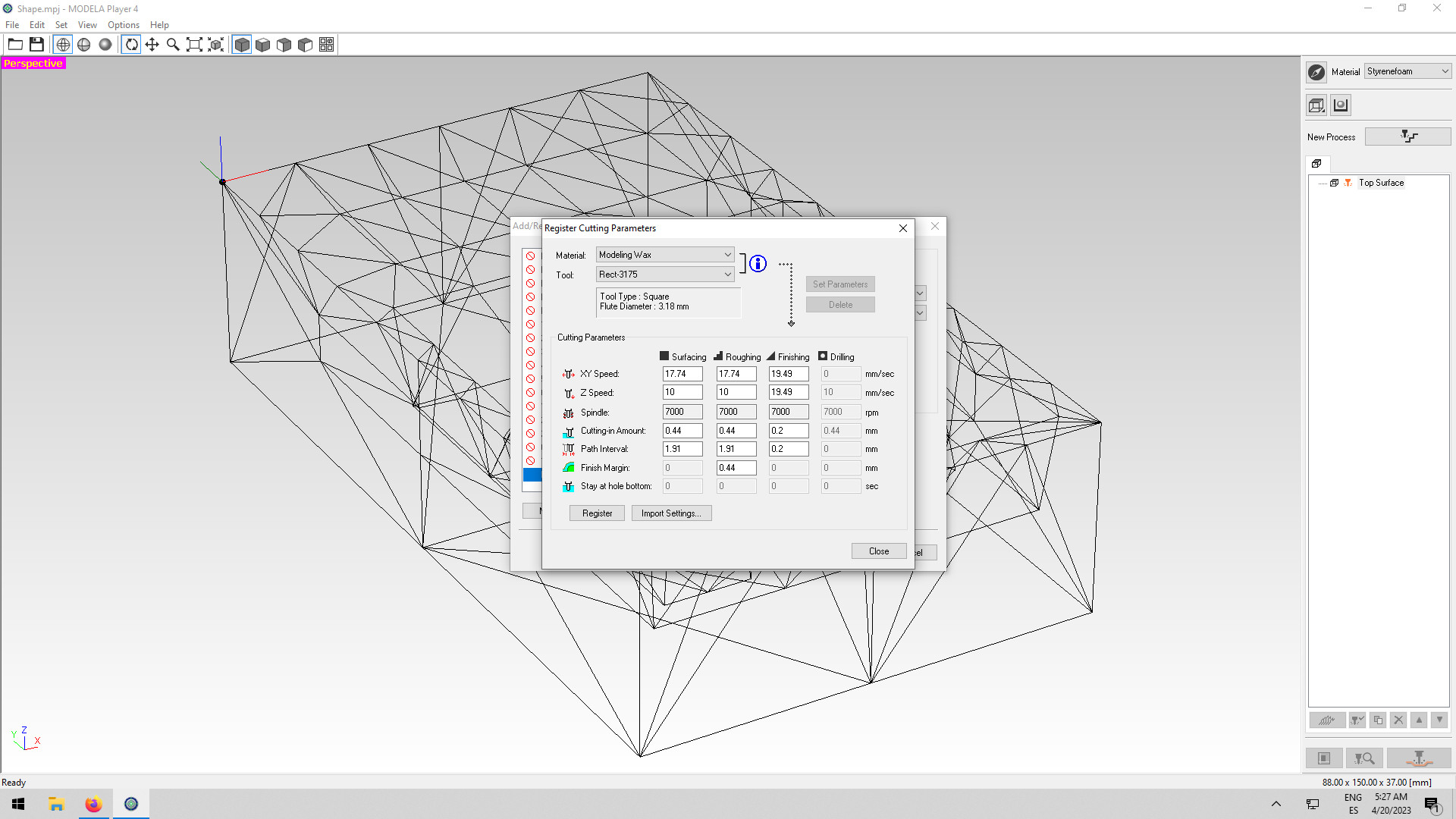
I also updated the material for "modeling wax" and registered the parameters (I didn't do any changes here). Now I could start the process of preparing the file for the machine.
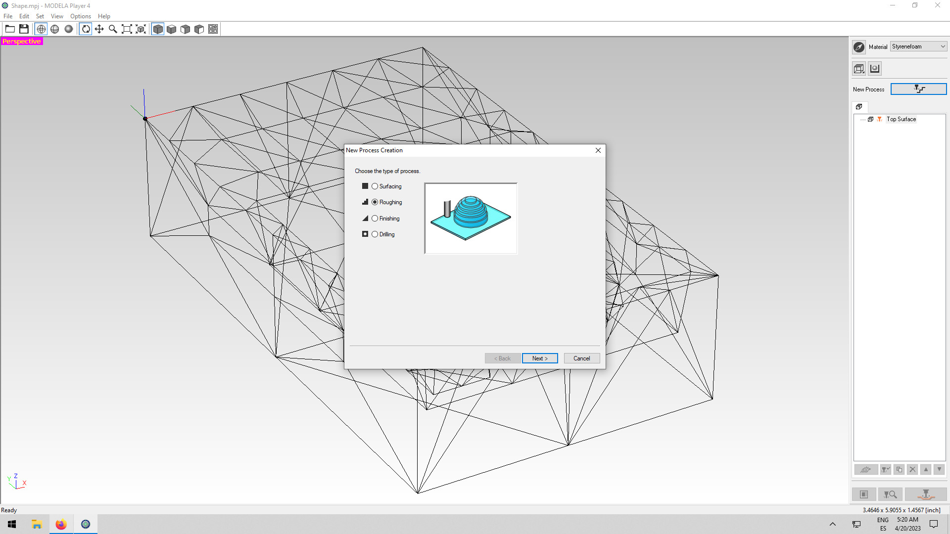
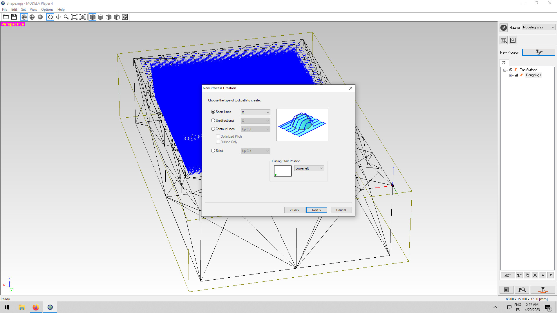
Defining the parameters for roughing
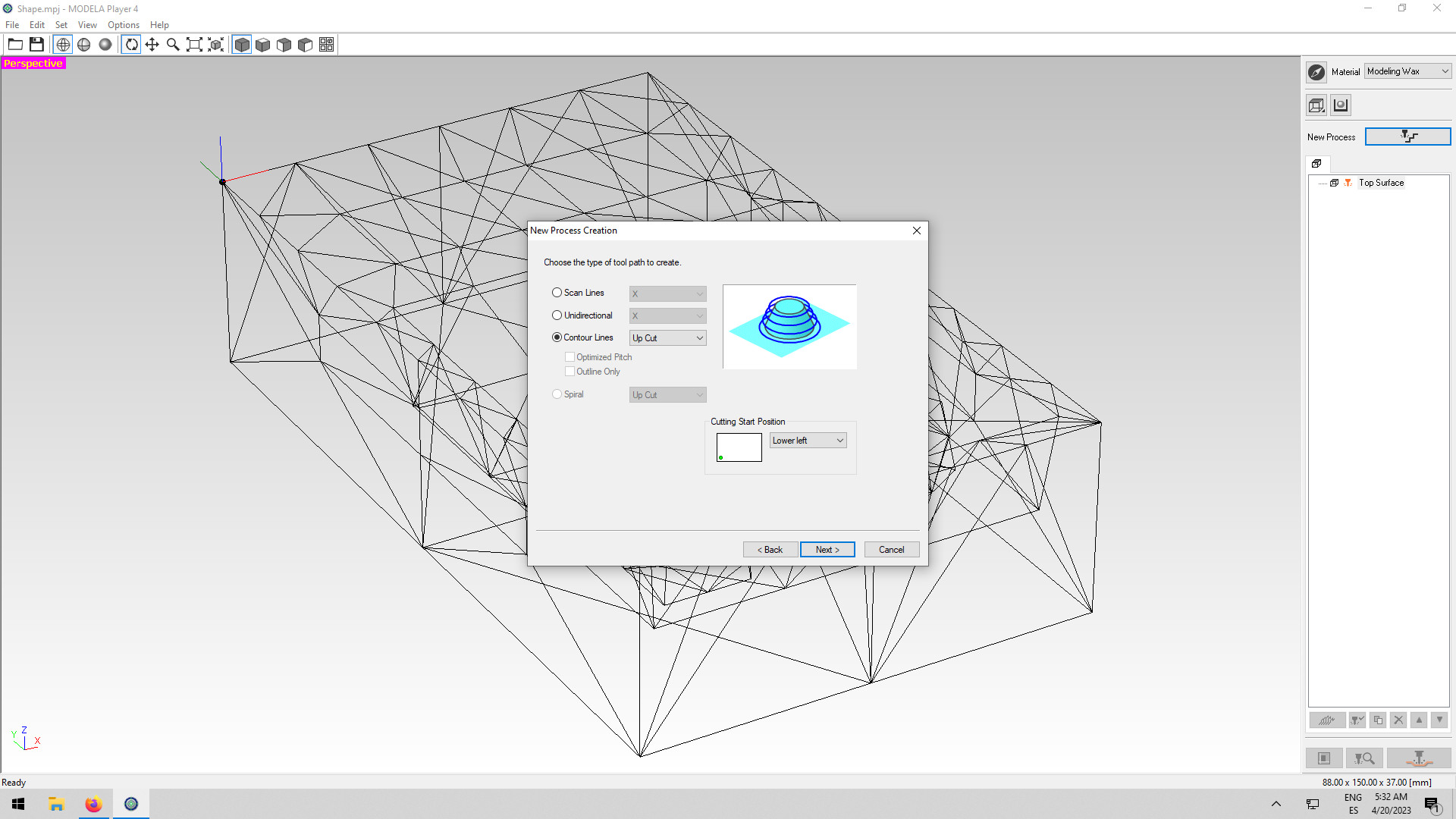
I started by clicking on "new process creation", then I selected "roughing", roughing is the process of milling the majority of the material, so it's a longer process than the finishing. After I selected the roughing I needed to choose which tool path to use, I selected the "contour lines" and then "up-cut", this says that the wax is pulled out of the material (if not with the pressure and heat the wax could actually melt into the material).
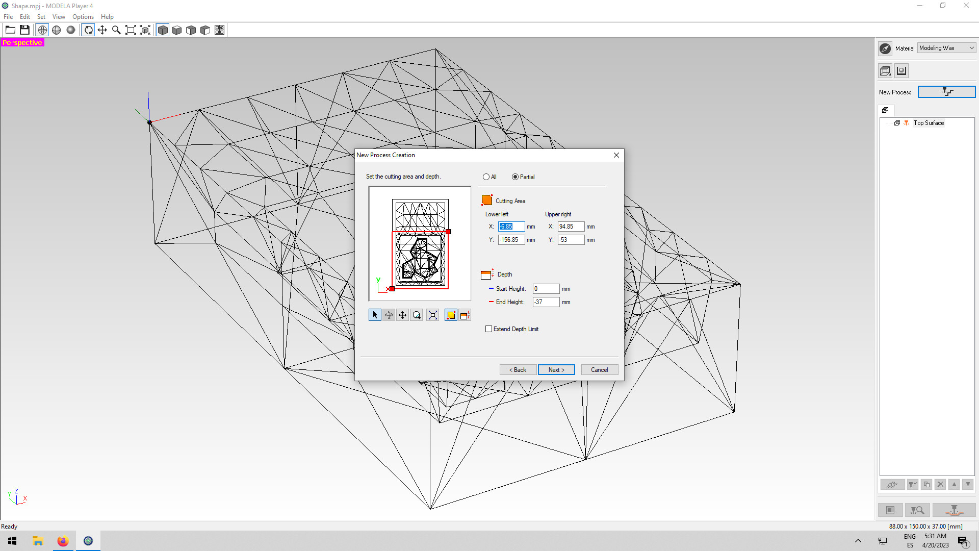
I also defined the area of work and saved those parameters so that I could use the same area when setting up the finishing.
Finishing
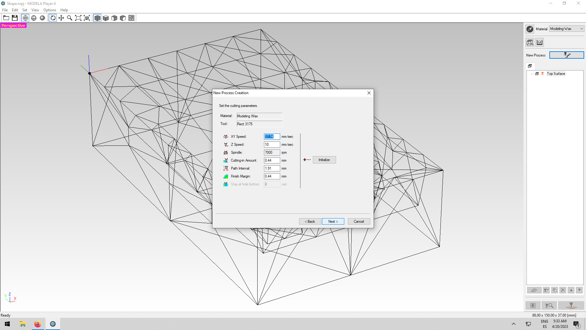
For setting up the finishing file I used the same process. I started by adding a new tool 1/16 (1,59mm). Then I went on to set up the parameters again. I choose "finishing" this time and then defined that the type of tool path would be "scan lines" in the X direction.
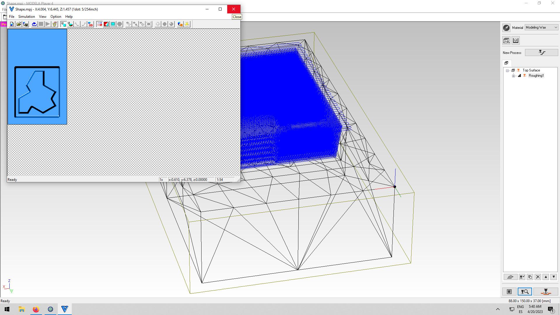
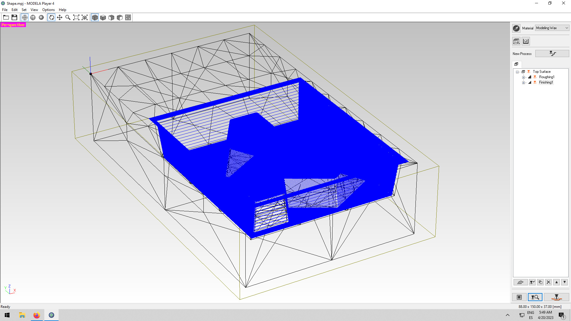
I pre-visualized the process of the milling and everything was ok so I saved it (PRM).
Preparing for milling
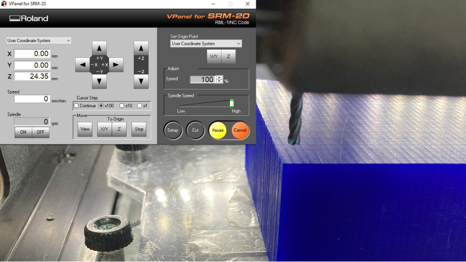
Now that I had the files it was time for machining. This machine SRM-20 is the same one we have been using for the PCBs so this process was quite straightforward.
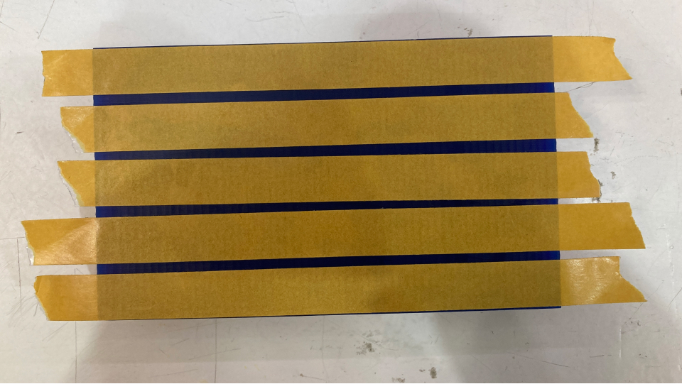
I started by adding the double-sided tape into the wax and gluing it to the bed of the machine. Then I set up the x and y origin points by moving the endmill to the same origin point of the wax. Before doing this I added the endmill I was going to use for roughing, the 1/8 (3,175mm).
To set up the z origin I moved the endmill close to the wax (in the center of the wax) and dropped it by hand. Once it was set up I defined it as the z origin.
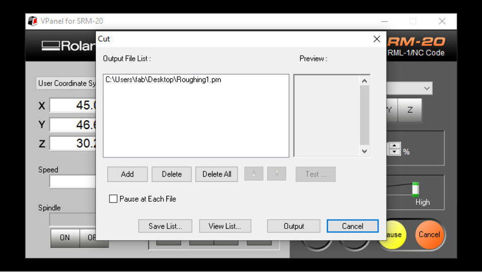
I then added the roughing file by clicking "cut" uploading the file and clicking "output".
The origin was wrong...
When the machine started it went to the origin and then it stopped... I changed the origin points in the file and it was still not working. Then I decided to go back and check the Rhino file and I realized I had the x and y coordinates swapped, so I aligned the wax model properly and exported the STL again to open it in the Modela Player 4 software again. I exported everything again and it worked well this time!
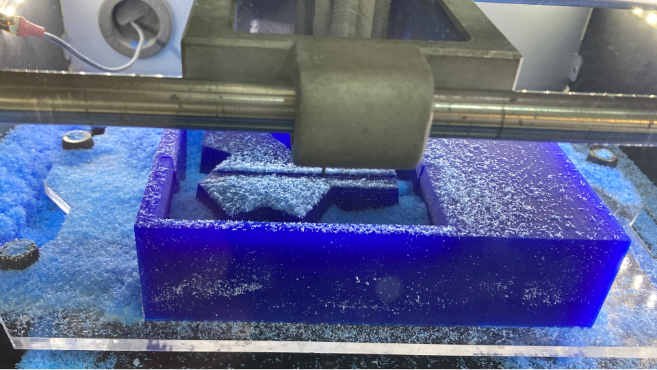
Milling
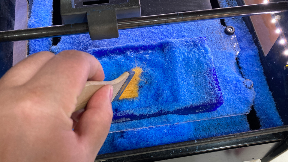
The milling of the roughing took a really long time, about 4h, but then the finishing was quite fast, about 1,5h. Once the roughing was done I just changed the endmill and calibrated the z origin again using the same process as before.
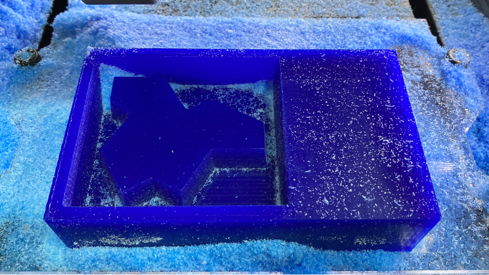
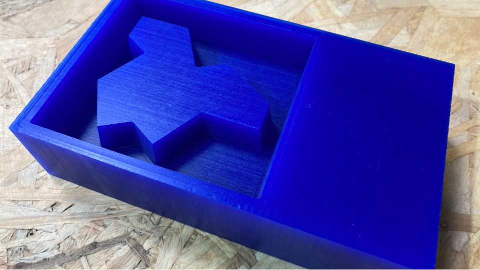
Molding
Once my milling was all done I had a perfect wax mold, so I was quite happy with it. Now it was time for filling in the mold with silicone to produce the mold for the tiles.
Measuring how much silicone to prepare
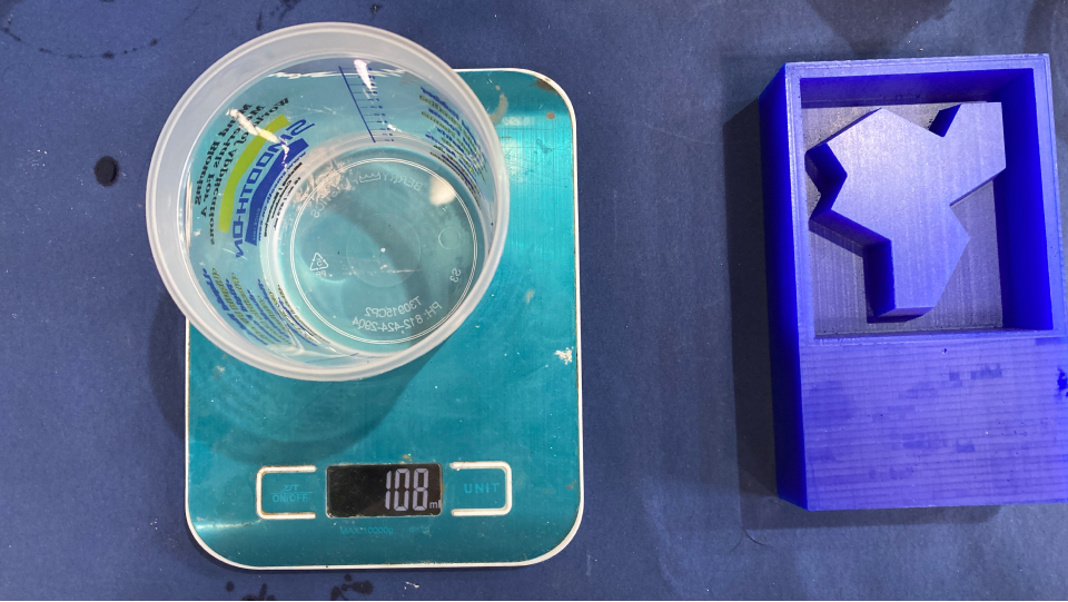
Before mixing the silicone I needed to measure how much silicone I would need to fill in my mold. To do this we can use water and that is what I did.
So I simply pour water into my mold and then put that water back in an empty one and measured on a scale how much it was. It was roughly about 108g so I gave a bit of weight to it to be comfortable (and also include the weight of the plastic cup I was using which was 18g). So I pointed the weight to around 135g/140g.
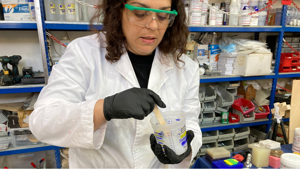
Measuring the silicone and mixing it
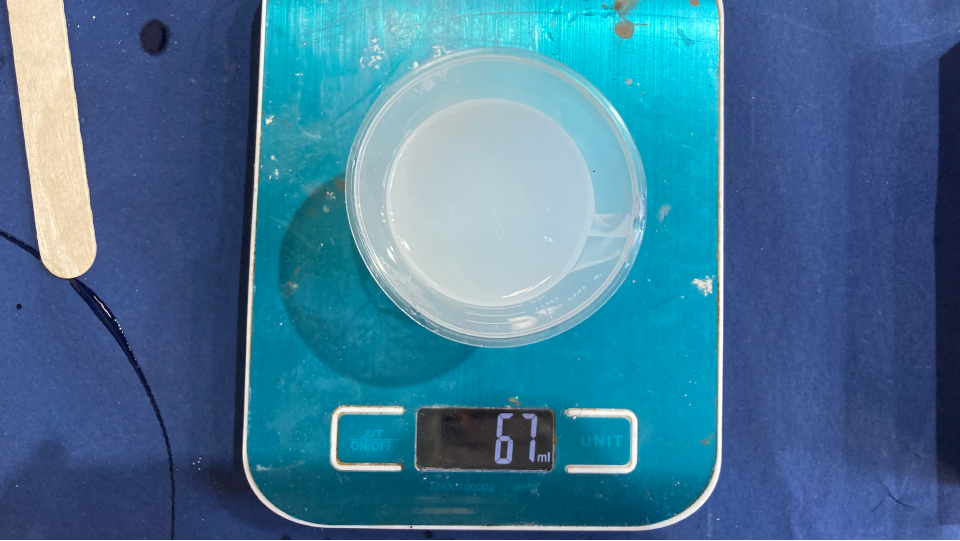
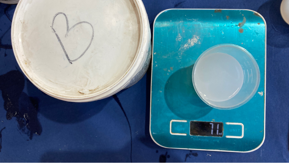
For this specific silicone mix - EASYPLAT 00-30, by Feroca there are two parts, A and B, and they need to be added in equal amounts 50/50. So I started by measuring the A and then the B to have half the total weight I needed for each so that together they will have the amount needed to fill in the mold.
This combination can be worked within 30m, but after that is not good anymore.
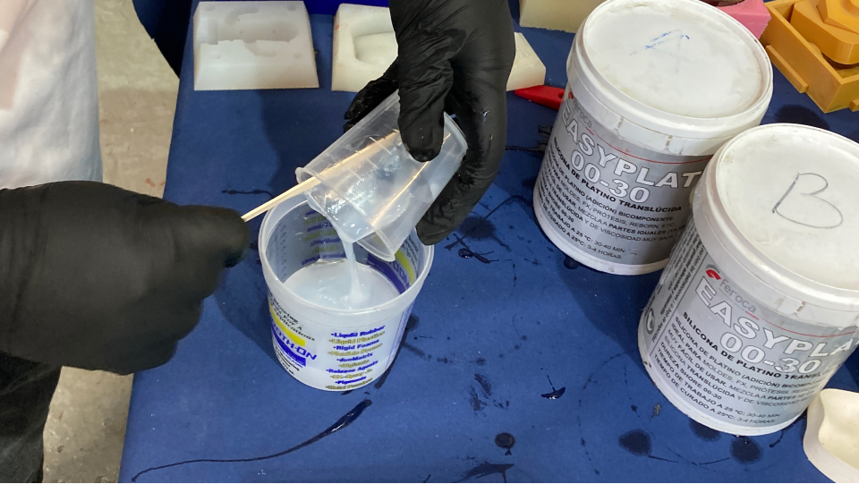
Then I just mixed the combination about 10m, making sure I was grabbing the mix from the walls of the cup too.
It is important to refer that when it comes to working with chemical reactions we should use some safety gear such as glasses, a coat, and gloves. It's also important to wash our hands very well before and after using the silicone. After use the silicone should be kept well closed and labeled in a fresh, dry, and with good ventilation place. The EASYPLAT 00-30 silicone is a platinum-curing silicone, so substances such as water, impurities, organic tin catalyst, acids, alkalis, and other sulfur, phosphorus, and nitrogen-containing organisms will influence the vulcanization of the rubber which can cause its inhibition and malfunction. Therefore, we shouldn't mix or touch those substances during the operation process.
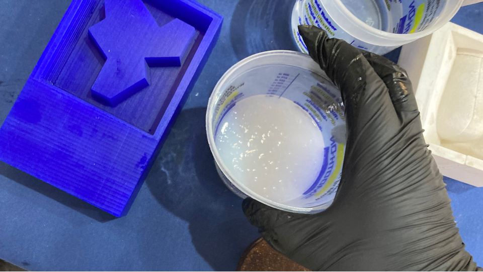
Once the mix was ready we could start to see the bubbles appearing - they start to move to the top, we can beat the cup a bit on the table to help the bubbles come up.
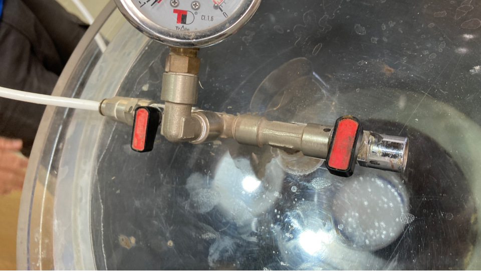
With this mixture is not really necessary to use the vacuum chamber, but I wanted to give it a try. It works by adding pressure and making the trapped bubbles to come out to the surface faster.
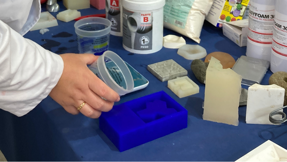
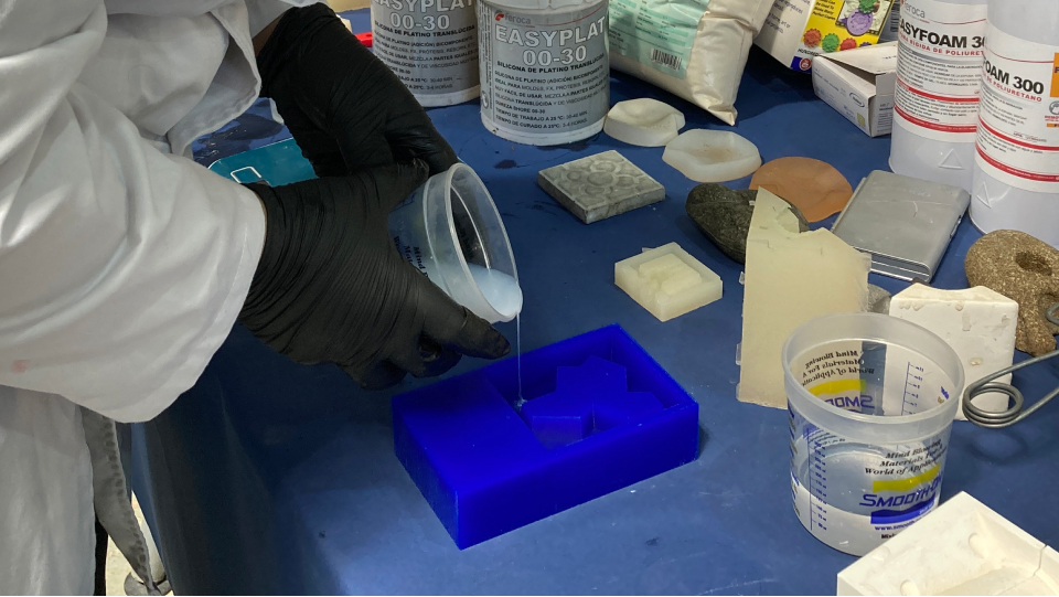
Filling up the mold
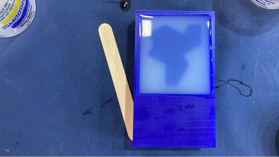
Once the bubbles were gone it was time to finally fill in my mold. To do this we should pour the silicone from the same spot and pour a really thin portion of it.
Then once filled in it was time to wait about 3-4h acording to the datasheet until it was ready.
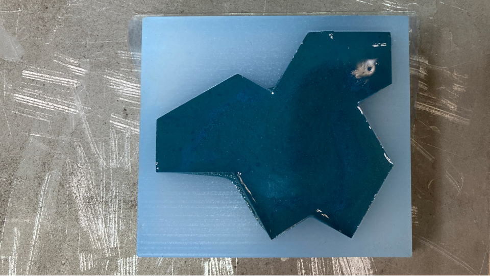
The mold
After waiting the mold was finally ready and it came out perfectly! I made sure I removed it carefully by grabbing one corner and pulling it out gently.
Casting
It was now time to cast my first tile!
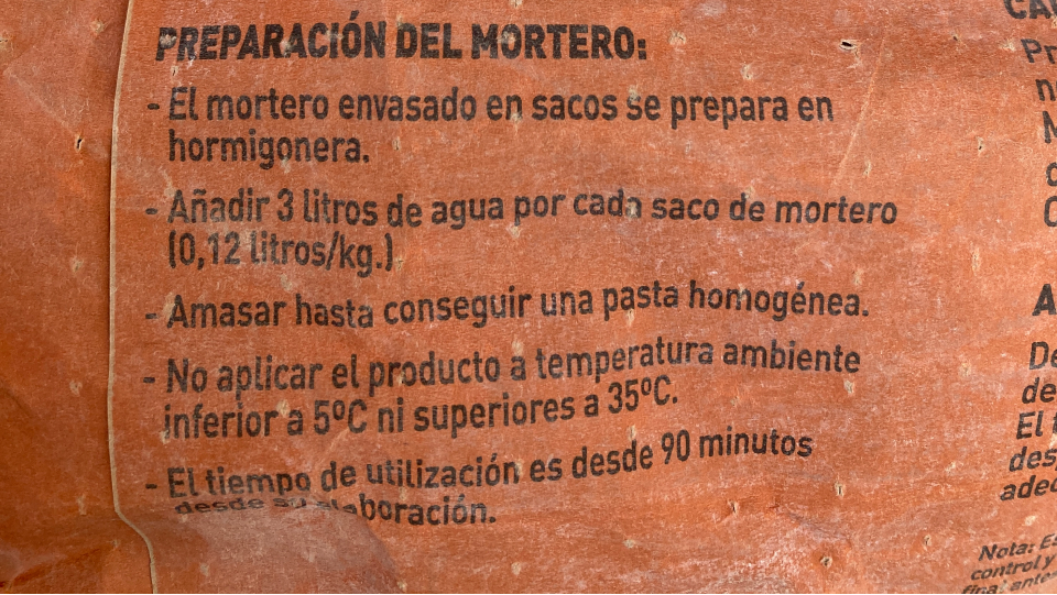
Datasheet of the cement
For my tiles, I wanted to use cement, so I just went ahead and used the cement we had at the lab. The instructions were in the bag itself. For 1kg of cement 0,12l of water.
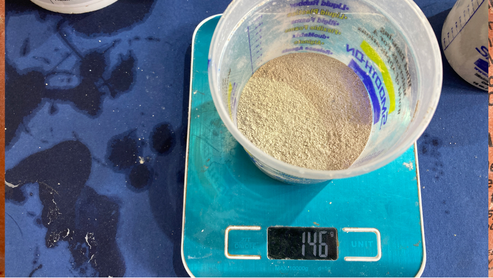
Mixing the cement
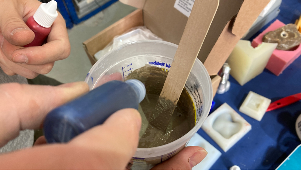
So I pour cement into a cup and measured it, then I did the maths to see how much water it would need. So if for 1kg of cement, we should pour 0,12l of water, for 0,146kg of cement we should pour 0,017l of water (17g). After mixing it for a while I also added a little of blue colorant.
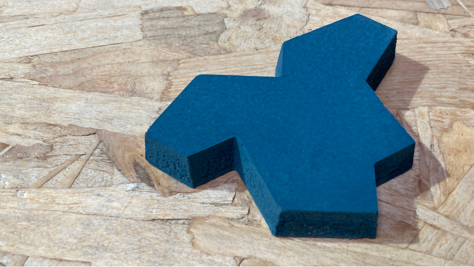
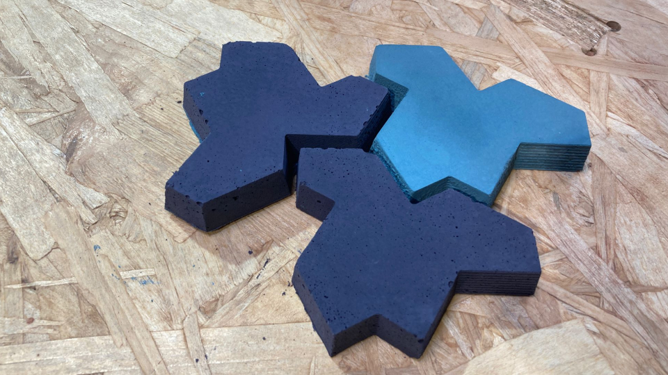
My first tile!
Now I just needed to wait between 24h up to 48h for the cement to dry.
I actually really enjoyed this week! I liked all the steps of the process and I didn't have any major difficulties.
I did learn some stuff though, I was reminded again of using the right software for the specific project we work on, I started with Figma and that was just not the right software to use. I also realized that setting up the file properly in Rhino can avoid some troubles with the origin. Also planning this week was important because we need to consider the drying times of the material.
Final project and input devices
I am not really sure where to use it, but I am quite fascinated with the possibility of doing a conductive soft object that people could interact with, sort of inspired by the game pod on the movie Existenz by David Cronenberg.