Susana Passinhas @Fab Academy 2023
07. Computer-controlled Machining
This week we learned about CNC (computer numerical control). CNC is subtractive (cuts away material) procedure (we can't create internal voids nor closed cavities), that allows the manufacturing of objects through the control of a computer (the computer controls the machine). It is a machine that can operate with multiple axes from 3D to 5D. We can definitely use the CNC machine for 2D, the difference between a CNC machine and a laser cut machine is that the CNC can handle(cut) ticker materials than the laser cut.
There are 2 types of motors: a router and a spindle. At Fab Lab Barcelona in our machine (Raptor X-SL 3200/S20 CNC Milling Machine) we have a spindle.
Group assignment
This week we needed to test how the CNC operates when it comes to cut plywood. For this test we did several lines to cut at different speeds and also we designed squares to test the inner and outter cut as well as pocketing. We learned the best speed (speed of the spindle) for the machine is 18000RPM (by checking the size of the chips it produced, between 1mm-3mm). Also we understood the difference between cutting conventional and climb. Conventional makes a less clean cut.
→ Group Page here
Designing furniture in 2D for CNC production
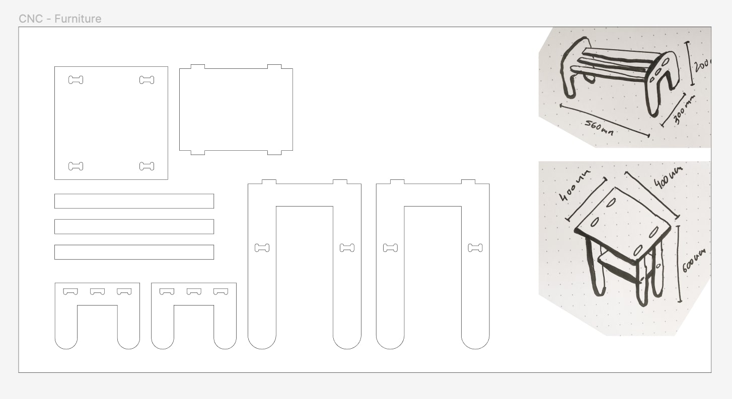
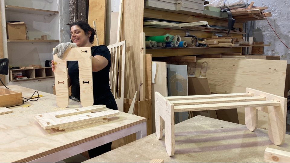
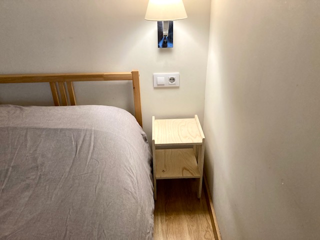
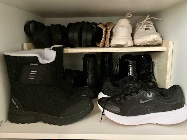
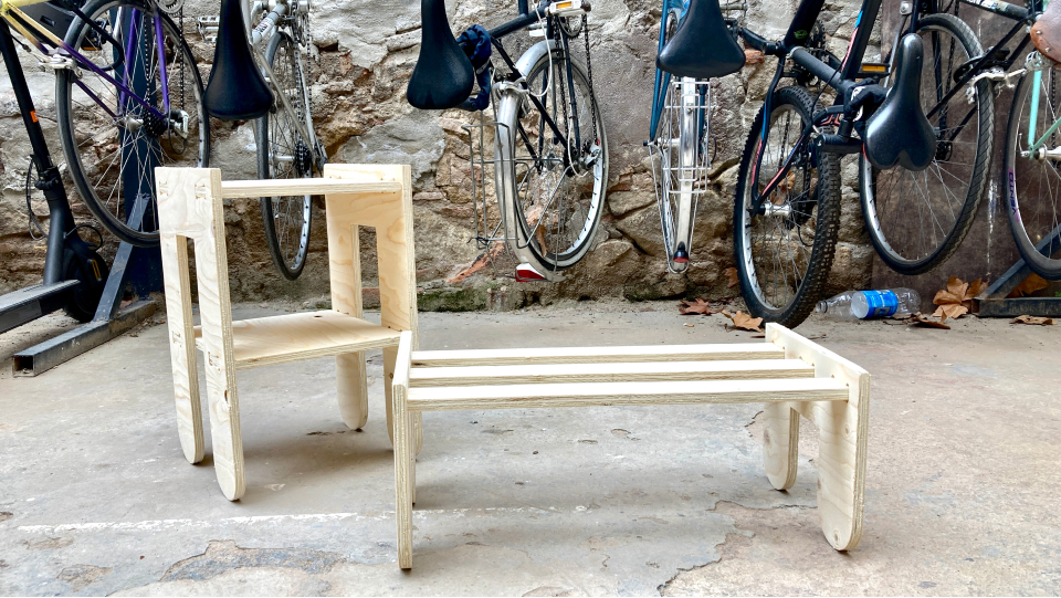
For this assignment, I wanted to build custom-made furniture that I needed for my house. I had specific measurements to work with and that is precisely how I started. I needed a shoe rack to go inside a cabinet and a bedside table (for a very tiny space) with a shelf.
Initial sketches
I started to sketch my initial thoughts and also looked for inspiration for CNC furniture on the web. I then moved my sketches into Figma (a software I am relatively fast) just to start to have an idea of the shapes and measurements I would need to design.
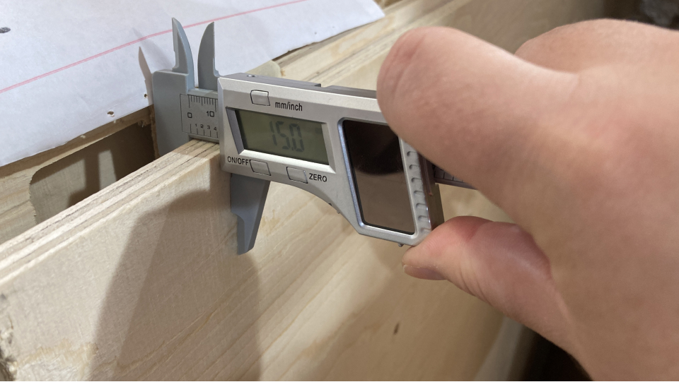
Measuring the material
The material we were going to work with is plywood. It has high impact resistance, a clean finishing and high strenght compared to weight.
Nevertheless, we always need to make sure of the material measures, so I measured all 4 sides and used the thickness measure to set up my measures so that I make sure I cut completely the material and also design the dogbones correctly. The plywood was 15mm in the 4 corners.
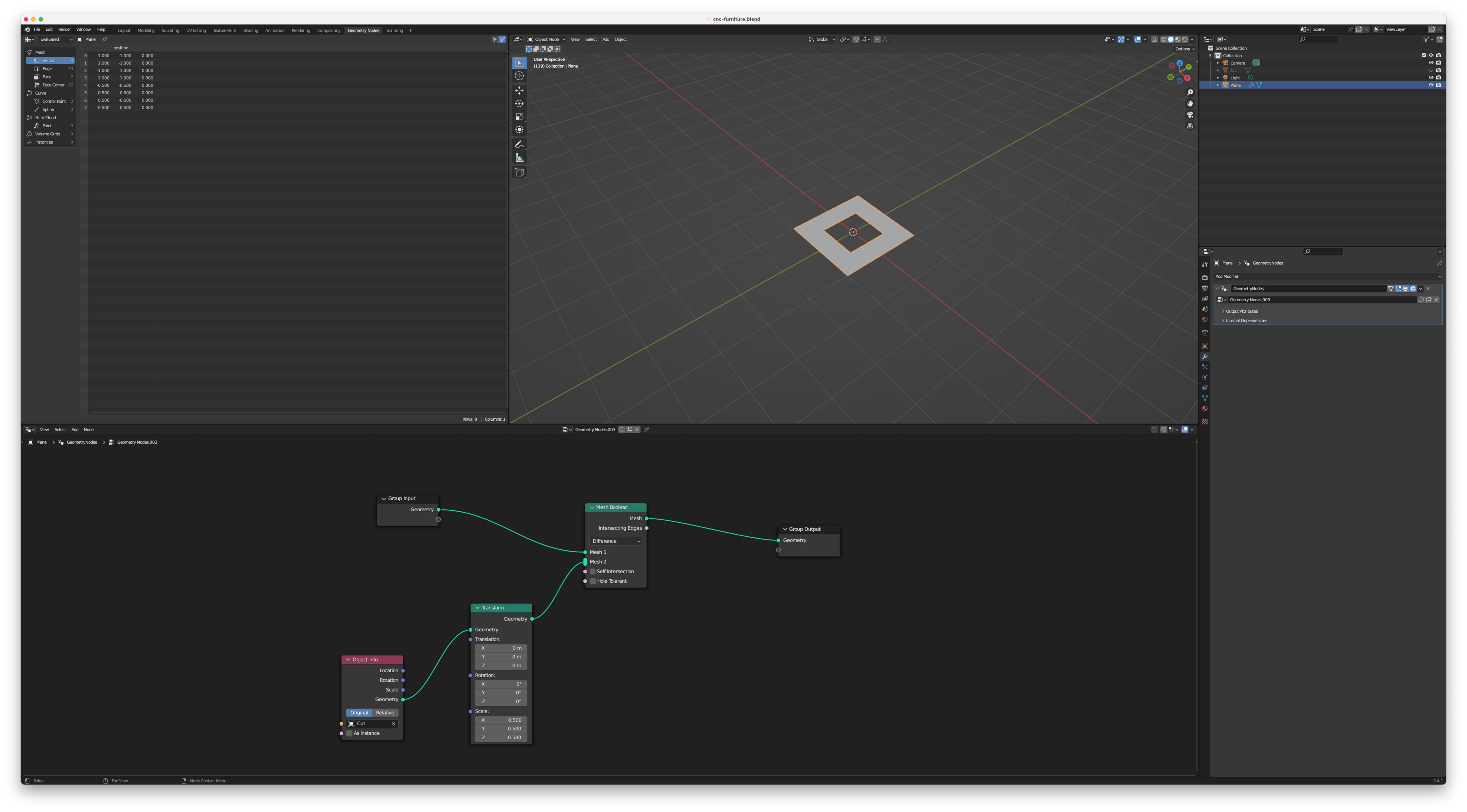
2D design in Blender
Then I had to choose which software to choose for this assignment...I knew we had to move the file into RhinoCAM so that we could prepare it for the machine, so I felt I should go with Rhino...but I have been enjoying exploring Blender as we move on the projects and it has been nice to explore doing parametric design there. Even though I always have to scale the Blender file in Rhino it is actually quite easy so I decided to give it a try again with Blender and make my designs parametric (the measure here I need to be parametric is the one based on the material thickness and tolerance, all the other measures are fixed as I am doing custom made furniture to fit specific places in my house).
But then, an hour into thinking about how to design and do booleans with curves (because we only need the 2D) I realized I was creating unnecessary complexity...
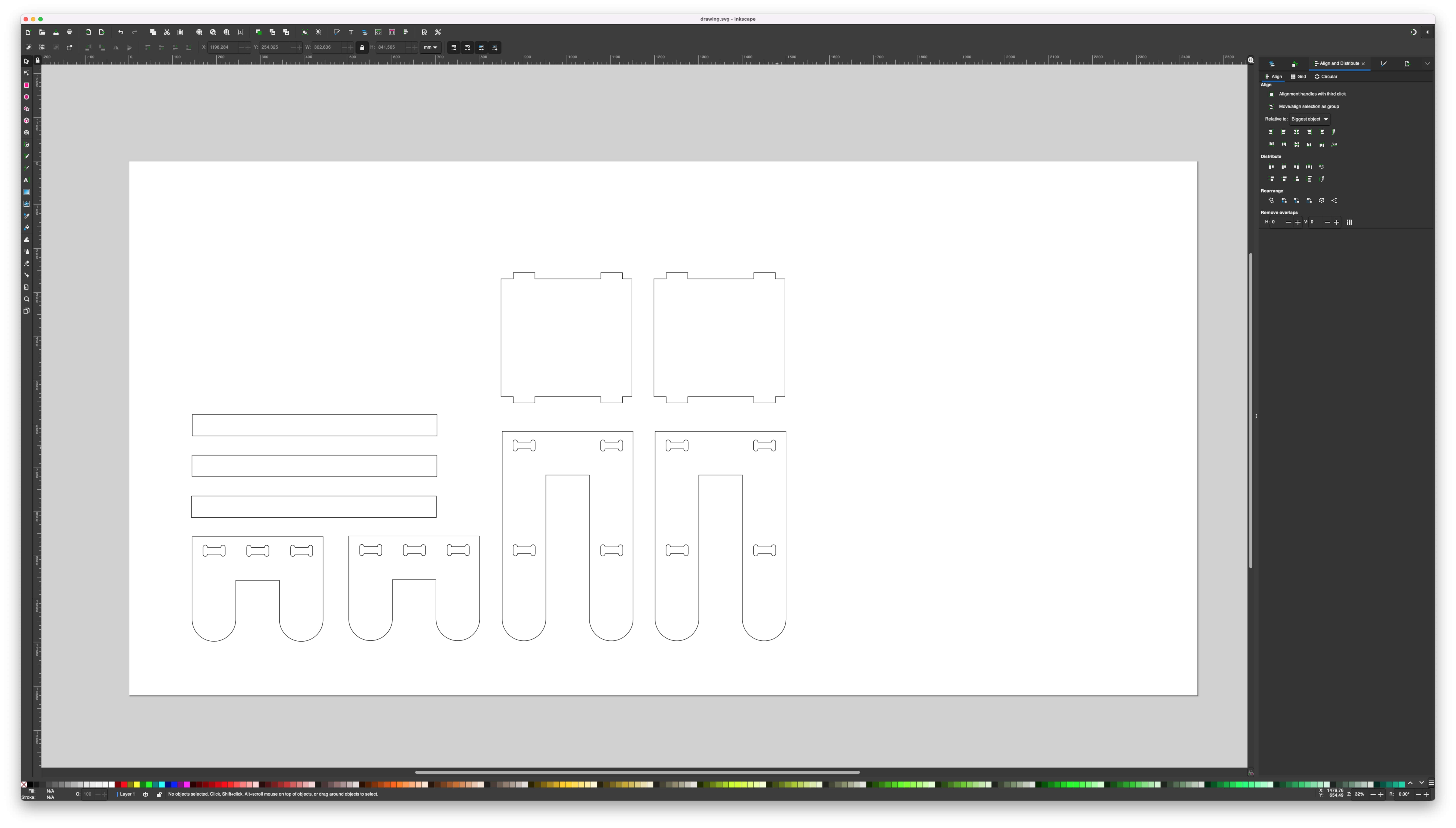
... changing to Inkscape
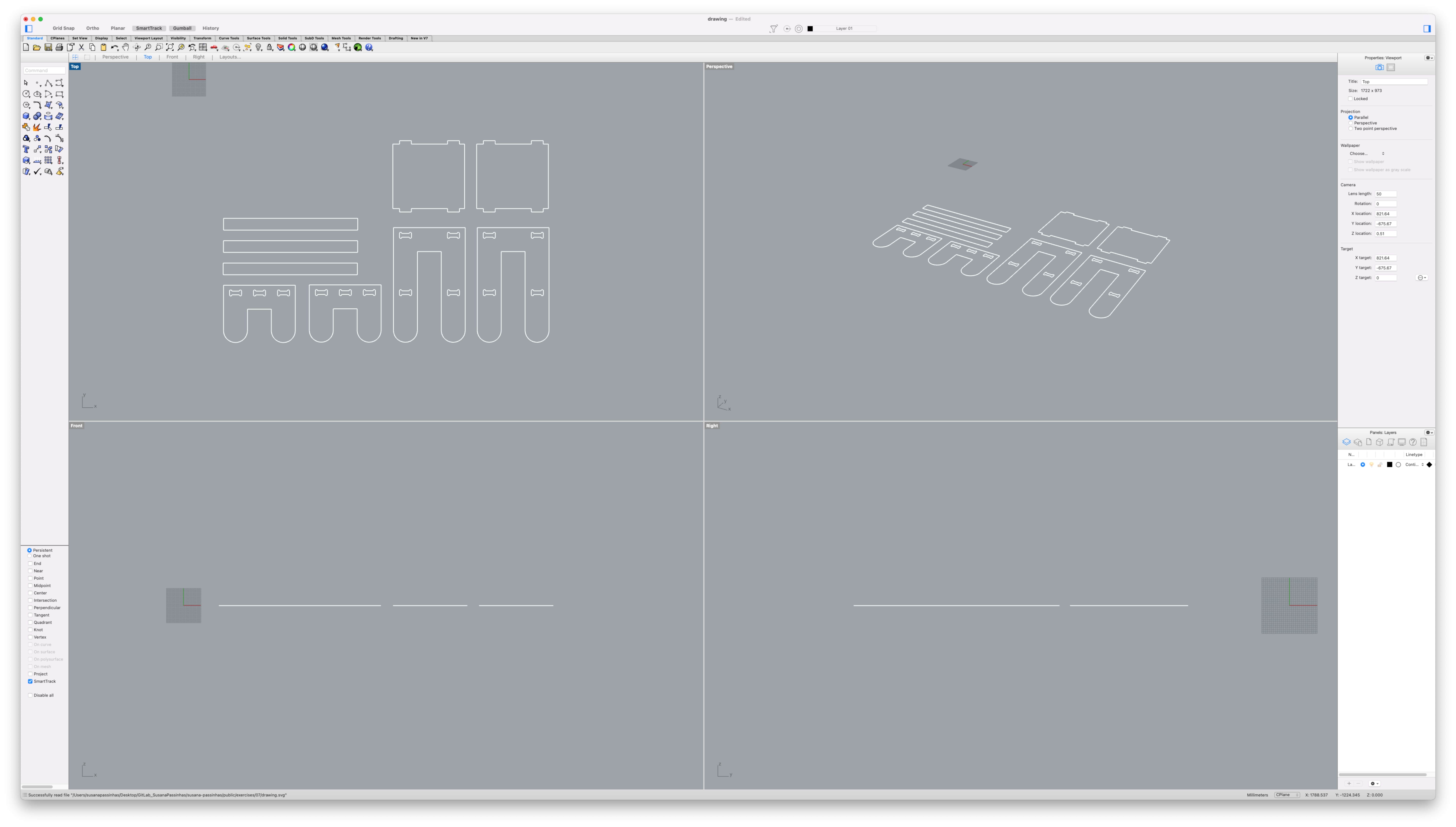
Because Figma doesn't work with millimeters, this was an opportunity for me to explore a bit further Inkscape. It was quite easy and intuitive and this time I locked the measurements so they didn't keep changing (something that happened the first time I explored this software). I first created a document with the measurements of the material (2440mm x 1220mm) and for the furniture I used the measurements I had took note of before.
For the dogbone's height, I used 15mm thickness with a tolerance of 0,5mm so that the pieces could fit nicely in the post-assembly. The dogbones are used because the endmill can't cut at 90 degrees, meaning, it will always be a curve when there is an angle of 90 degrees, because of that we use dogbones, which makes a little rounded space outside the angle (on the corners) and therefore allows the assembly to work properly.
Prototyping
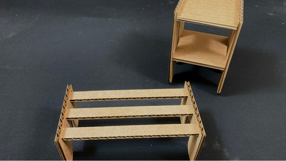
Before going into the CNC I did a prototype with cardboard just to understand if my concept would work (the joints, distances, and overall feeling) since it was my first time designing furniture.
Customizing for the lase cutter machine
After I designed the furniture in Inkscape I saved it as an SVG and opened it in Rhino just to make sure it was ok. Then I duplicated the file and did adjustments so that I could laser-cut the cardboard prototype.
In Rhino I simply used the command "scale" and used the material dimensions of the cardboard instead. So for the dogbone height of 15,5mm in plywood, I used 3,6mm instead (4mm cardboard considering the 0,2 kerf).
Then I saved it as a DXF and went to the laser cutter machine and followed the same procedure I did in week 3.
Cardboard 4mm
|
The result came out well and everything fitted nicely.
Preparing for the CNC in RhinoCAM
After the prototype was done and working well, it was now time to prepare for the CNC.
Setting up the file in RhinoCAM
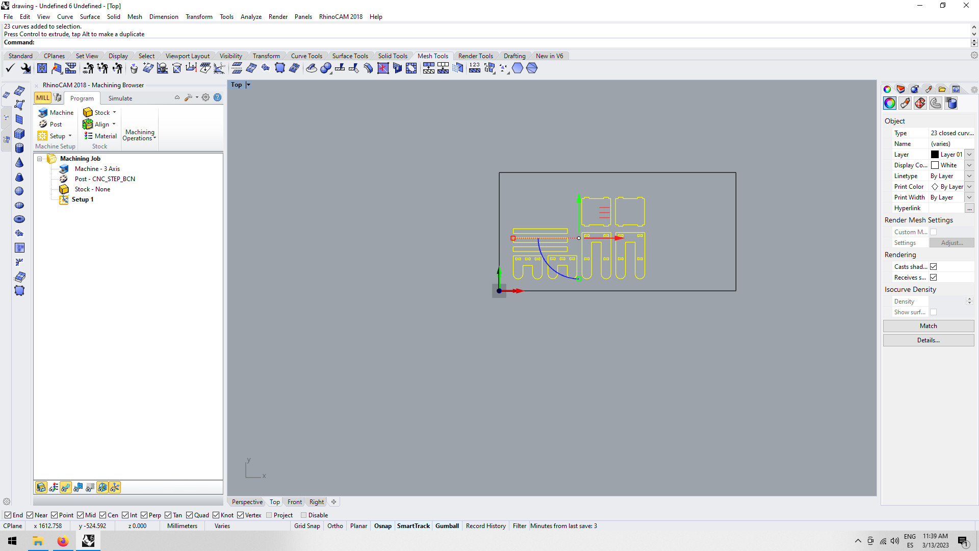
I opened my SVG file (the one that I had designed in Inkscape) with RhinoCAM. Under "Program" there are a few options to add the settings.
Defining the machine and postprocessor
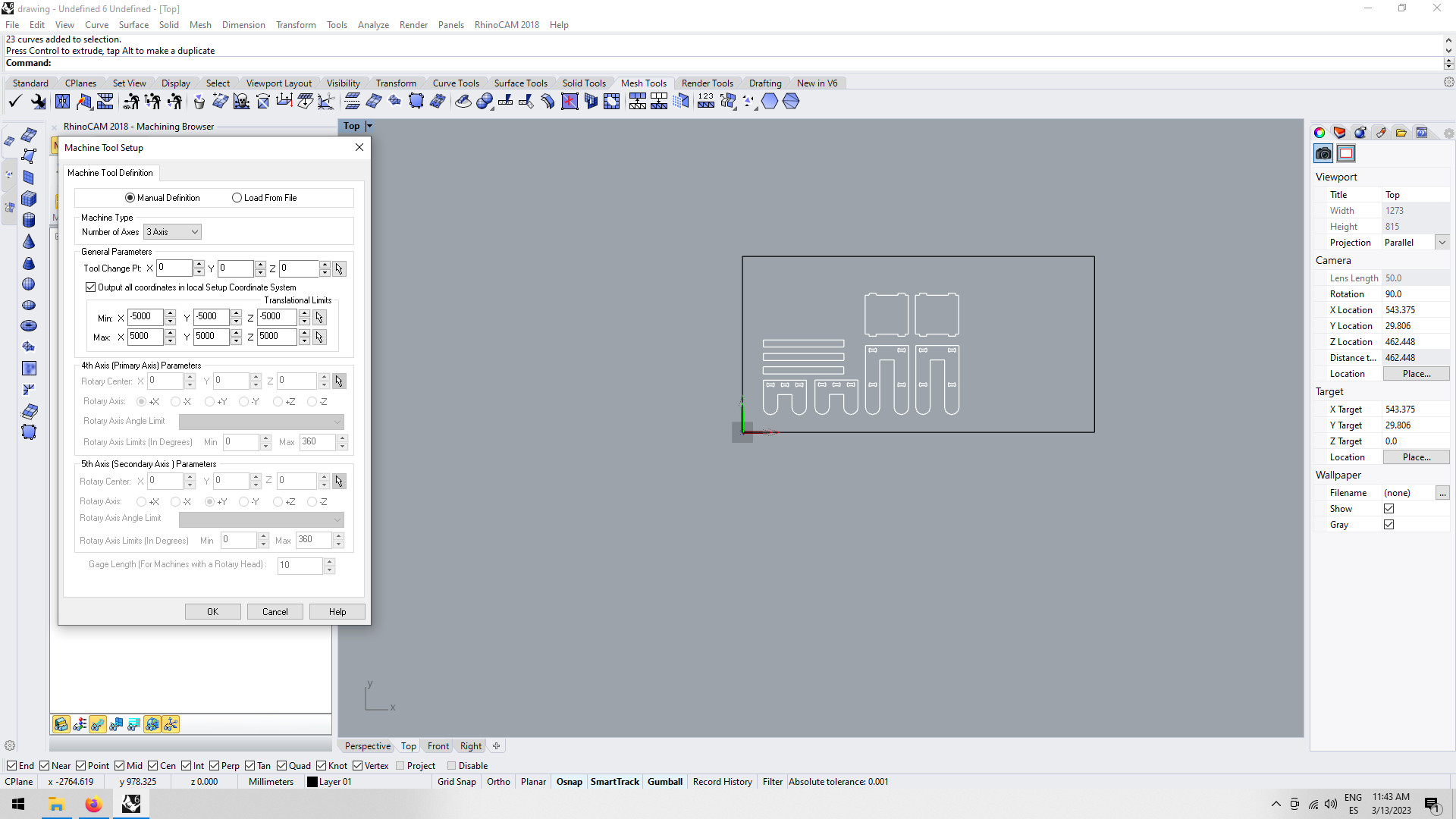
In the "machine" I defined the number of axis in the machine tool setup.
All the others settings I didn't change.
Defining the setup: stock geometry, material and work zero
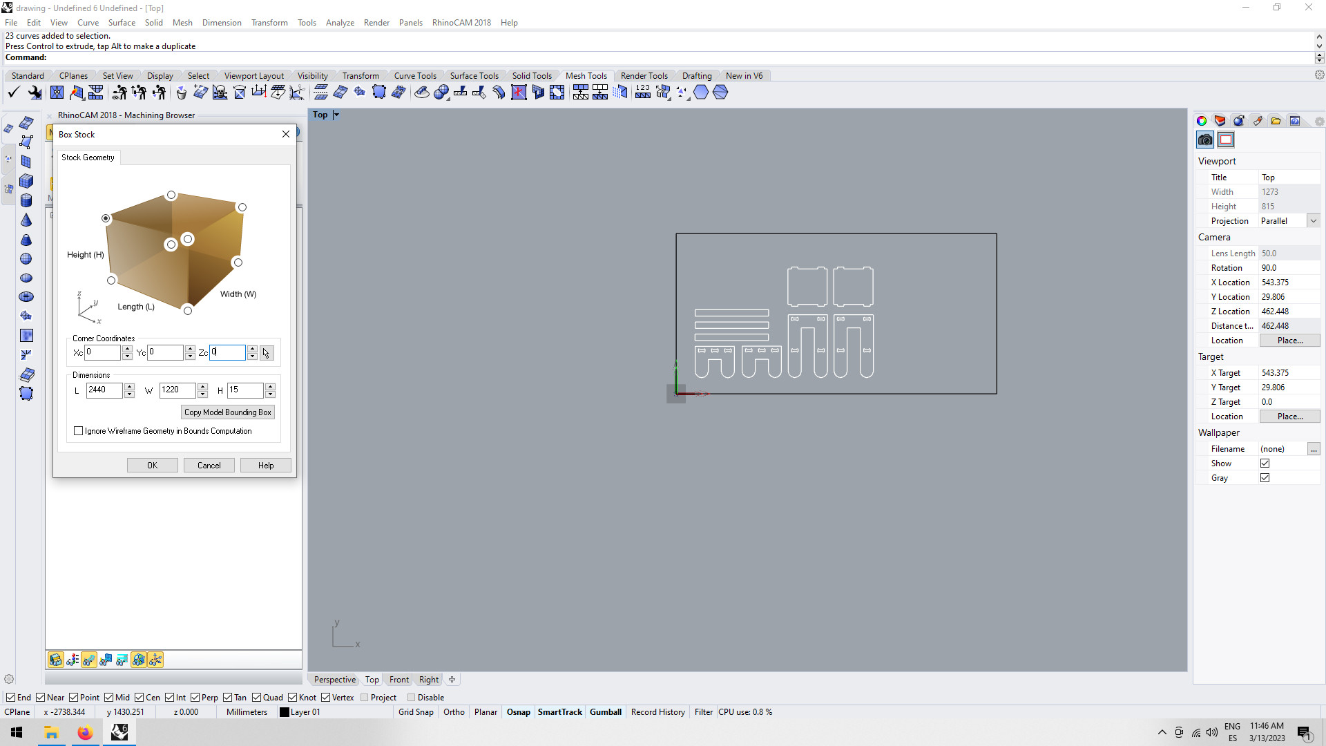
In the "Box Stock" I choosed the top left corner as a 0,0,0 point of my material and also added the dimensions of it. This setps up the machine in regards to the material and the design (were it is located in space). I also defined the material is wood.
Corner coordinated
Dimensions (of the material)
|
Creating and select a tool for machining
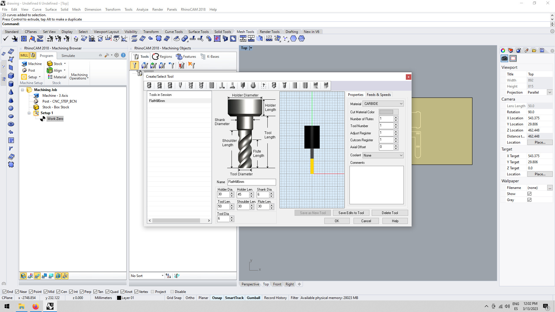
Then it was time to select a tool for machining. For this project I was going to use a down cut flat mill of 6mm (it cuts 3mm) with 1 flute.
Mill
|
I also updated the other settings, by measuring the mill.
|
Then I save it as a new tool "FlatMill6mm".
Profilling, pocketing and engraving
After adding the tool It was time to start setting the parameters for profilling, pockething and engraving.
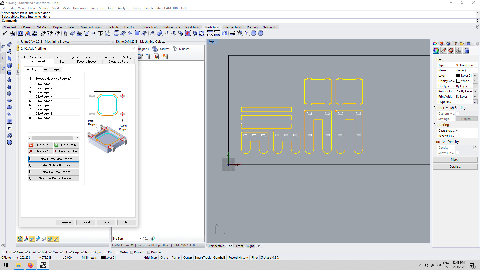
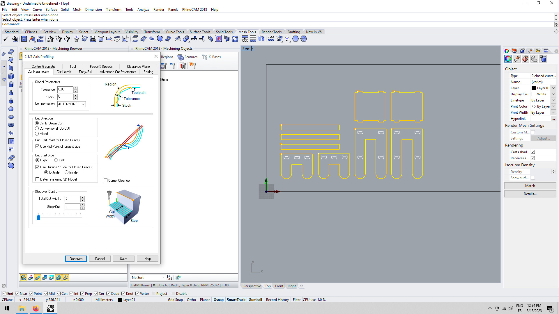
Profilling
Profile milling is a type of milling process, usually used to semi-finish or finish the vertical or slanted surfaces, including multi-axis milling of convex and concave shapes in two or three dimensions.
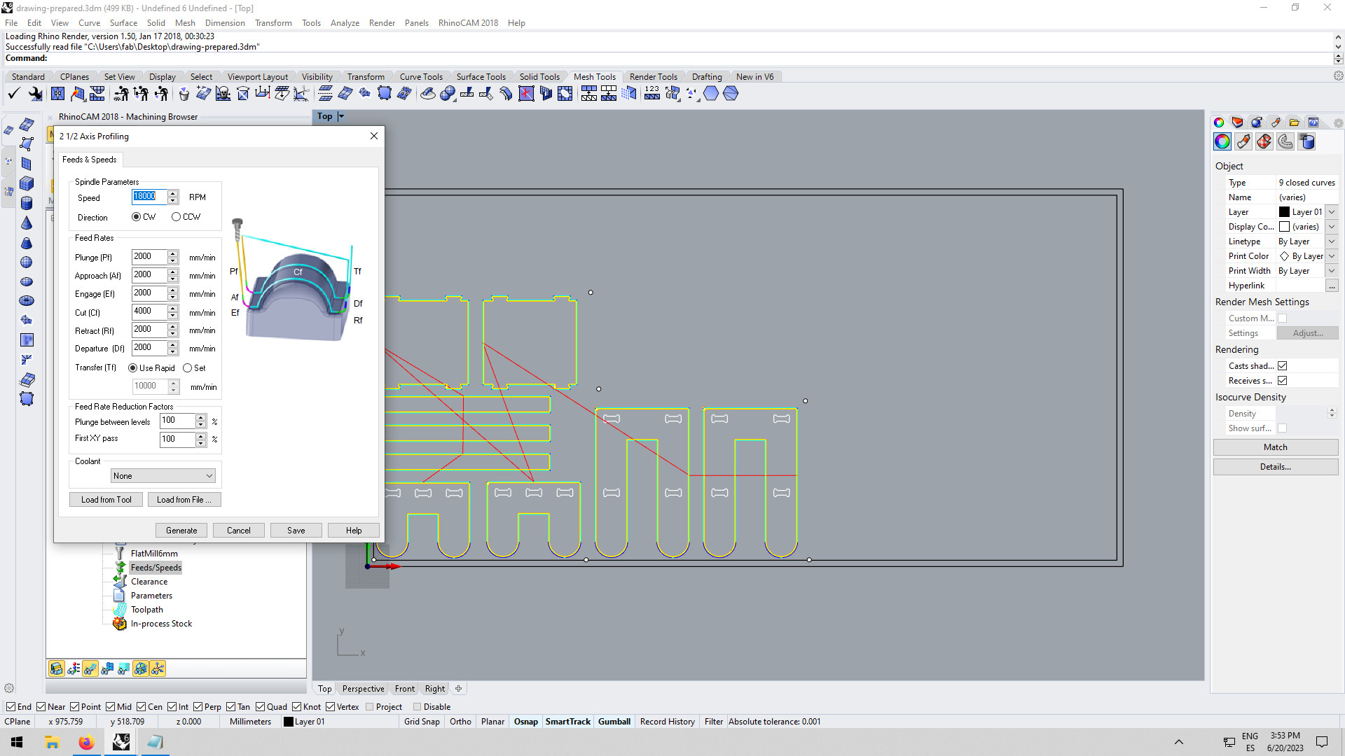
I used the chip load from our group assignment: 0,3mm at 18000RPM. I used the online calculator of the tool fabricant to calculate the cut speed which was 4000mm/min.
|
Feed and Speed
|
|
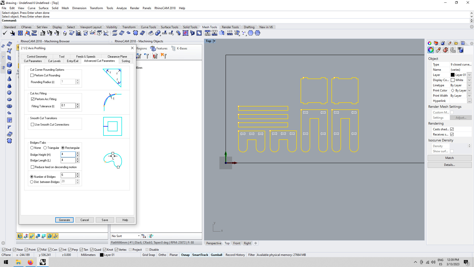
Advanced cut parameters
|
|
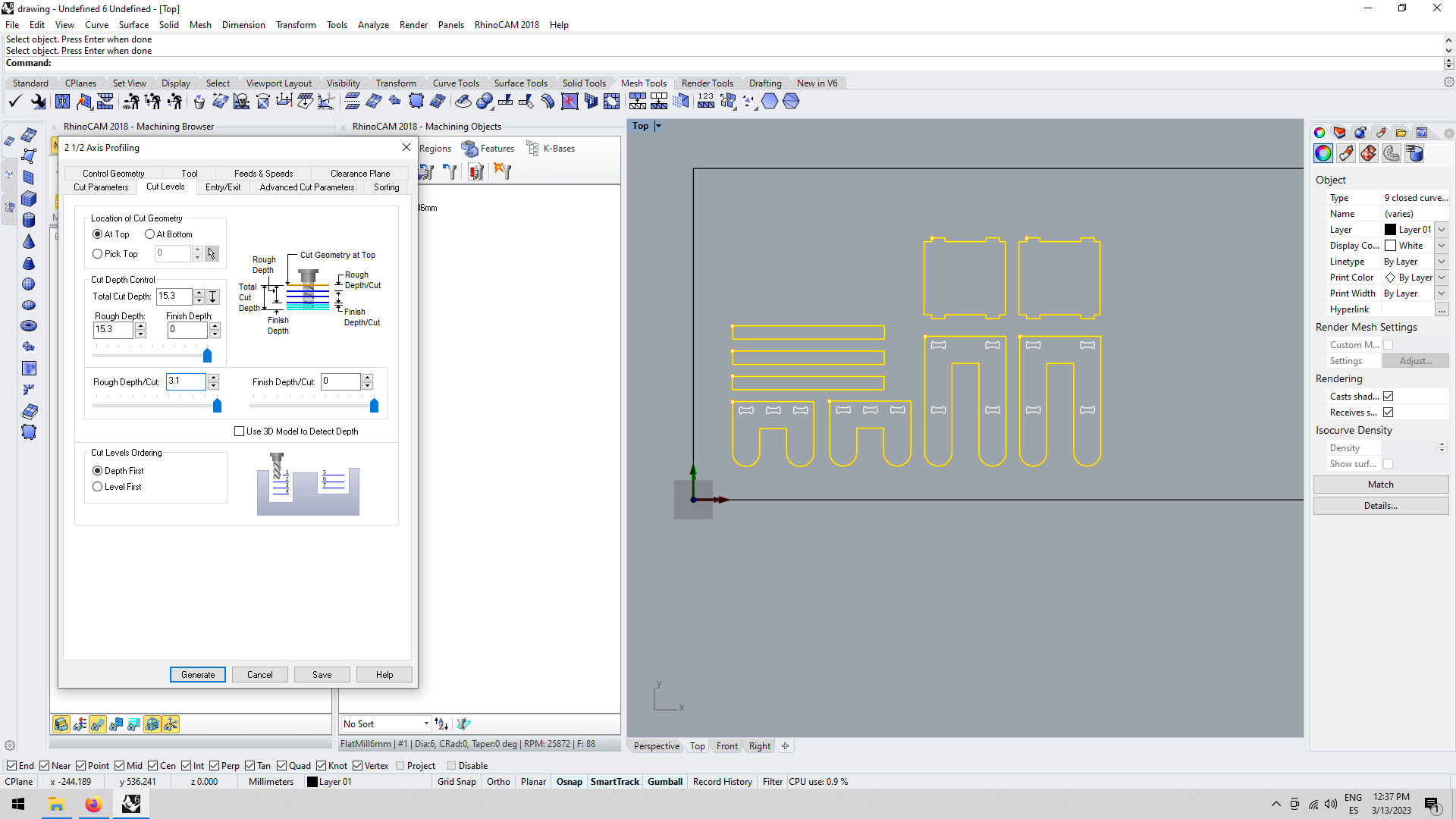
Cut levels
|
|
Cut parameters
|
|
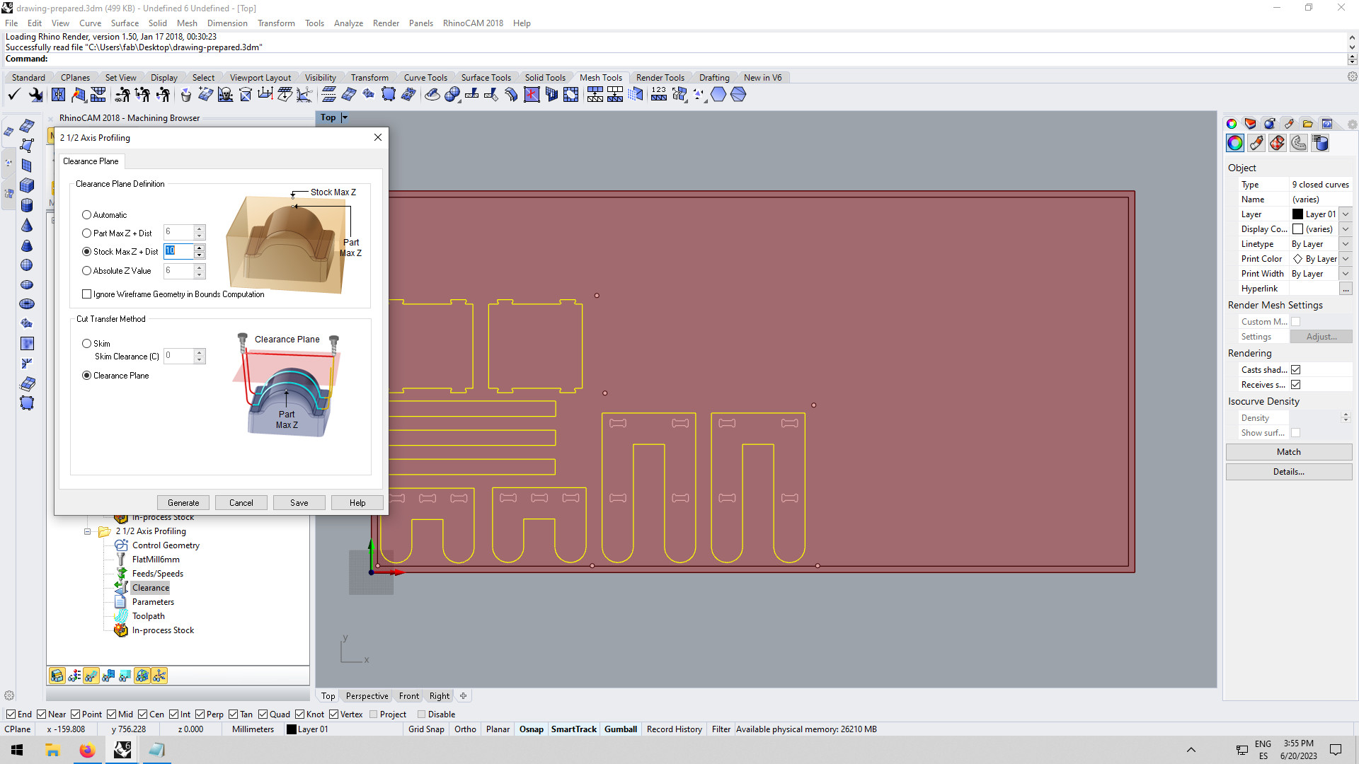
Clearence plane
|
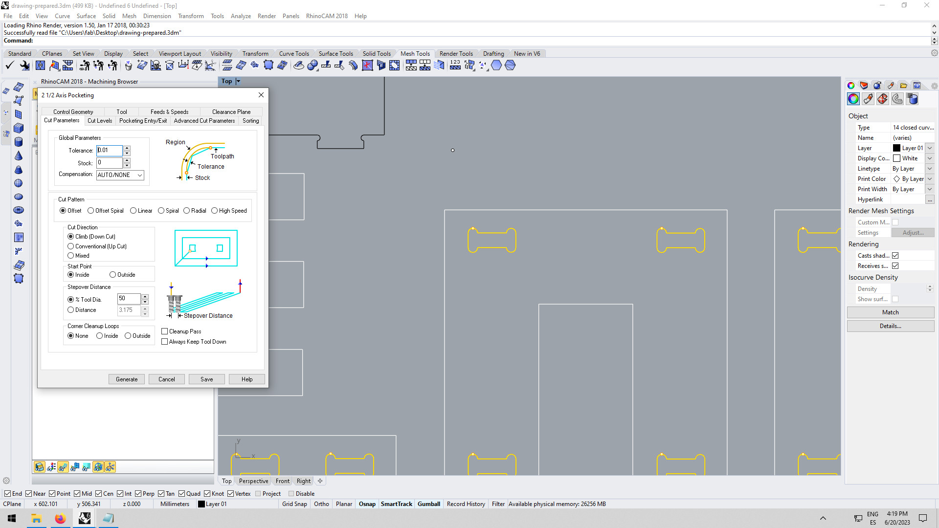
Pocketing
In the menu "machine operations" I choose "pocketing" and then selected all the parts I wanted to be applied. A Pocketing operation is used when you want remove all material with a closed boundary down to a set depth. Pockets can be programmed to cut through the full-depth of the materials or partial depth. In my case the pocketing was used for the joinery instead of profilling so that the entire material was removed instead of having a little pieces holding in the middle and that could have fly away. I used the same settings as before and just changed the following parameters:
|
Pocketing parameters:
|
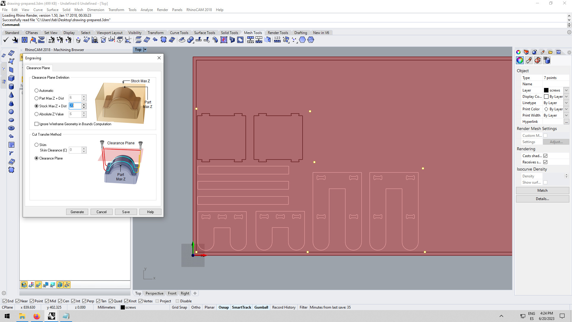
Engraving
Then, after running a simulation it was time to get ready for the machine, but before pulling the files into G-CODE another toolpath was added with screw points, that file was going to be pulled separately from the design ones. To do the screws file I used engrave (a subtractive process that removes material from a surface to create the desired shape). I used a clearance plane of 20mm (so that the endmill travels high from one point to the other, since the plywood is not at this stage stick to the bed of the machine with screws) and then 10mm from stock max for the cuts. In this operation I just engraved 3mm of the wood so that I could mark the position of the screws.
|
Clearence plane
Cut Levels
|
Operating the CNC
Now that everything was ready it was time to go to the CNC machine.
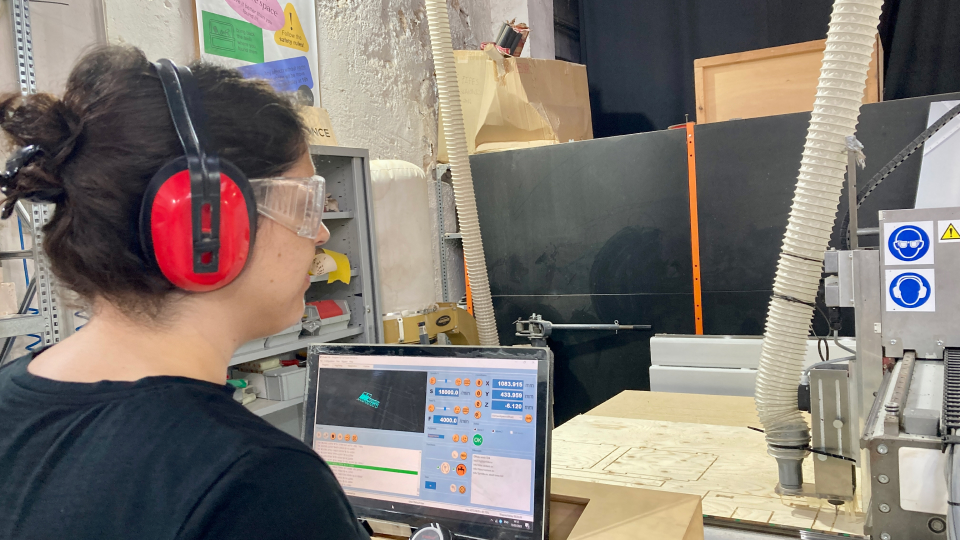
Safety measures
The machine we worked with for this assignment is quite powerful (Raptor X-SL 3200/S20 CNC Milling Machine) and it is important to take safety measures.
So before operating the machine, I picked up the protection glasses (objects can fly out of the machine because maybe they are small and not well attached for example), and hearing protection gear (because the machine is so loud).
I also made sure not to wear loose clothes and to tie up my hair.
I made sure at all times I was behind the operator's stand and I stayed controlling from there. There are a few emergency stops in the machine, one is right next to the operator's stand.
Also by the machine, there is a fire extinguisher. I also made sure I put on the dust extraction so that the chips (leftovers of the material) do not heat up and set a fire before the machine started to mil.
Setting up the machine to the initial position
Before being able to screw the screws to the bed I needed to calibrate the axis of the CNC. So after the plywood was in place I moved the mill to the 0,0 of the plywood and then set up the Z using the little piece we have, that needs to be centered, then in the computer, I set up the Z by clicking "customize z".
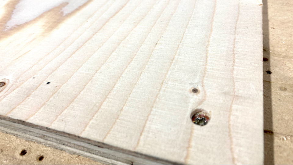
Screwing the plywood to the bed
Once the axis was set up well I run the G-CODE for the position of the screw. Then I went ahead and screw the screws. It is important to screw the material very well to the bed so that the plywood doesn't move and the cut is good and there are no flying pieces too.
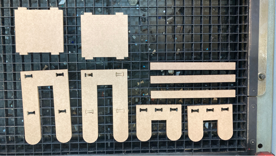
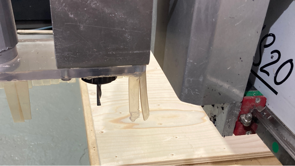
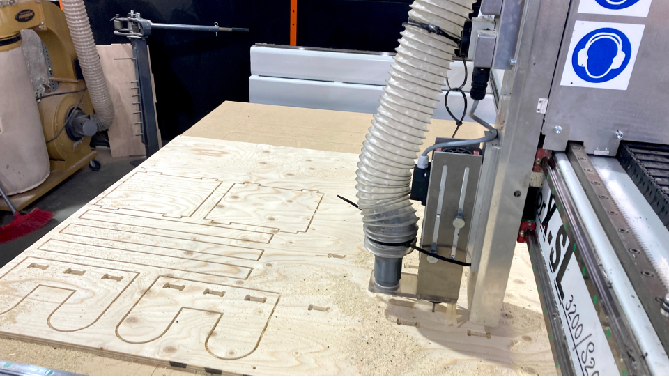
Milling
While milling I made sure to keep myself in the operator stand and check if everything was going well. This milling took approx. 30m.
Once the cutting was finished I moved the spindle to the edge and went up the machine to remove the bridges with a hammer and another tool, then I unscrew all the screws, removed the plywood leftover and pieces, and vacuumed the table.
Sanding
The plywood pieces needed sanding to smoothen the edges. So I went ahead and sand it by hand, making sure I entered the dogbones as well. I noticed the plywood because it's composed of layers, if the cut is in the direction of the layers it detaches a bit.
→ Files here
Reflection
When I started this week I felt a mix of excitement and fear. I was really excited because I could build furniture but also scared because it seemed like a very dangerous machine where I could get hurt. It was hard to overcome the fear of the machine and I felt a lot of tension during the entire week, until the day of the cutting. At the end of the day of the cutting, I took all the safety procedures and everything went well. It is actually very empowering to build my own furniture and I felt very accomplished.
Final project and CNC milling application
Not completely sure if I will need to use the CNC machine at the moment.