Susana Passinhas @Fab Academy 2023
03. Computer controlled cutting
Computer controlled cutting is the usage of computer software to design objects defined by parameters to send to cutting machines, such as laser cutting machines and vinyl cutting machines.
Group assignment
For the group assignment, we started by measuring the material: cardboard (2,7mm), acrylic (3mm), and wood (3,9mm). Then we created a file in Rhino for each material and did a comb with thickness variations, going from the thickness of the material to intervals of 0,5mm (decreasing and increasing). With this, we could test how much the kerf should be for these materials so that we can do our press kit properly (the kerf is the tolerance we needed for each material).
At the machine we started by turning on our smoke extractor, then we turned on the machine (Trotec Speedy 400) and focus the laser. We can focus the laser by using a small piece we can hang on the laser and make the bed of the machine go up until it touches and falls. We do this with the material already in the machine's bed. Once the focus was set we went to the computer to send the file to the machine.
We started with acrylic. At the computer, we opened the file in Rhino (a .dxf file) and used the command "print". This opens a dialogue where we can define some settings such as the type of material. We also made sure we were using the colors of the cuts we wanted (cut and raster/engraving). Then we opened the machine's software and add the job to the cutting area. We also double-clicked the colors on the left side and added the following parameters for each material:
Acrylic
- Engrave: Power(60.00), Speed(100.00), PPI/Hz(1000)
- Cut: Power(60.00), Speed(0.50), PPI/Hz(20000)
Wood
- Engrave: Power(60.00), Speed(100.00), PPI/Hz(1000)
- Cut: Power(75.00), Speed(0.50), PPI/Hz(1000)
Cardboard
- Engrave: Power(90.00), Speed(90.00), PPI/Hz(1000)
- Cut: Power(30.00), Speed(1.00), PPI/Hz(1000)
|
We made sure we were positioning the laser at the place we wanted to optimize the cut (we can also see the positioning of the layer in the machine's software). We realized that in our acrylic test all the possible kerfs we add to the "comb" were not enough so we had to do it again.
Later, when I went to do my own assignment I understood that the measures we took on Friday were not correct, we used the leftover material and the material we had to work with had different measurements. The cardboard had 3,8mm (instead of 2,7mm) and the Acrylic was 2,7mm instead of the 3mm we measured before.
→ Group Page here
Parametric press-fit construction kit
Planning how to do it
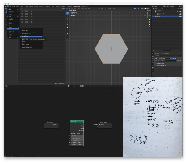
I wanted to build my parametric press-fit in Blender and explore the geometry NODES. This week in class we saw that we could build it differently depending on the software, for example in Fusion 360 we could use the components and parameters to create a shape like a triangle with the kerf and then make that triangle follow a circular pattern. In Rhino we used Grasshopper to do the same, though we created the entire shape and then we identified the middle points of the edges and created planes there that would cut the shape.
Those were the 2 concepts I had in my mind when I opened Blender. I started with a quick sketch on paper to better understand what I was doing.
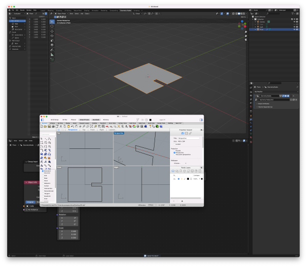
Testing Blender in Rhino
Since the machines at the lab work with Rhino, before I started I wanted to test if it was smooth to export a Blender file into Rhino. I exported it as an OBJ file and it was all good. So I was good to start.
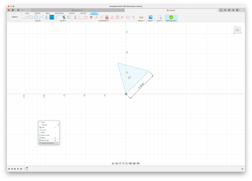
Trying it in Fusion 360
My initial idea was to follow the logic we did use Grasshopper in Rhino. I went to search for tutorials online and felt that finding the middle vertice using geometry NODES wasn't going to be so easy. After dragging some NODES and trying to understand what I was doing I got really frustrated so I went to Fusion 360 to design there. I remembered the principles of parameters and components so I designed a triangle and started to constrain the sizes. Then I wanted the triangle to sit straight and it was really hard for some reason to control the rotation of the object. I then remembered that we had used a circular pattern for the triangle to follow along and I thought this could actually work in Blender, so I went back to Blender.
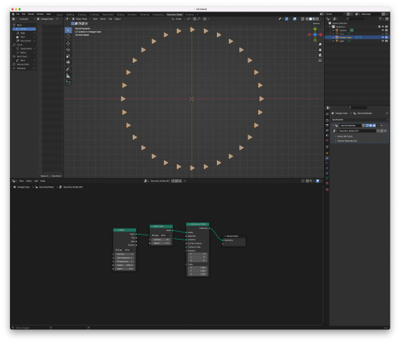
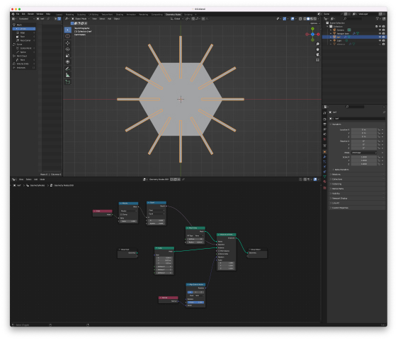
Circular array
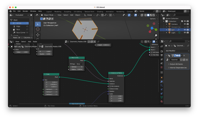
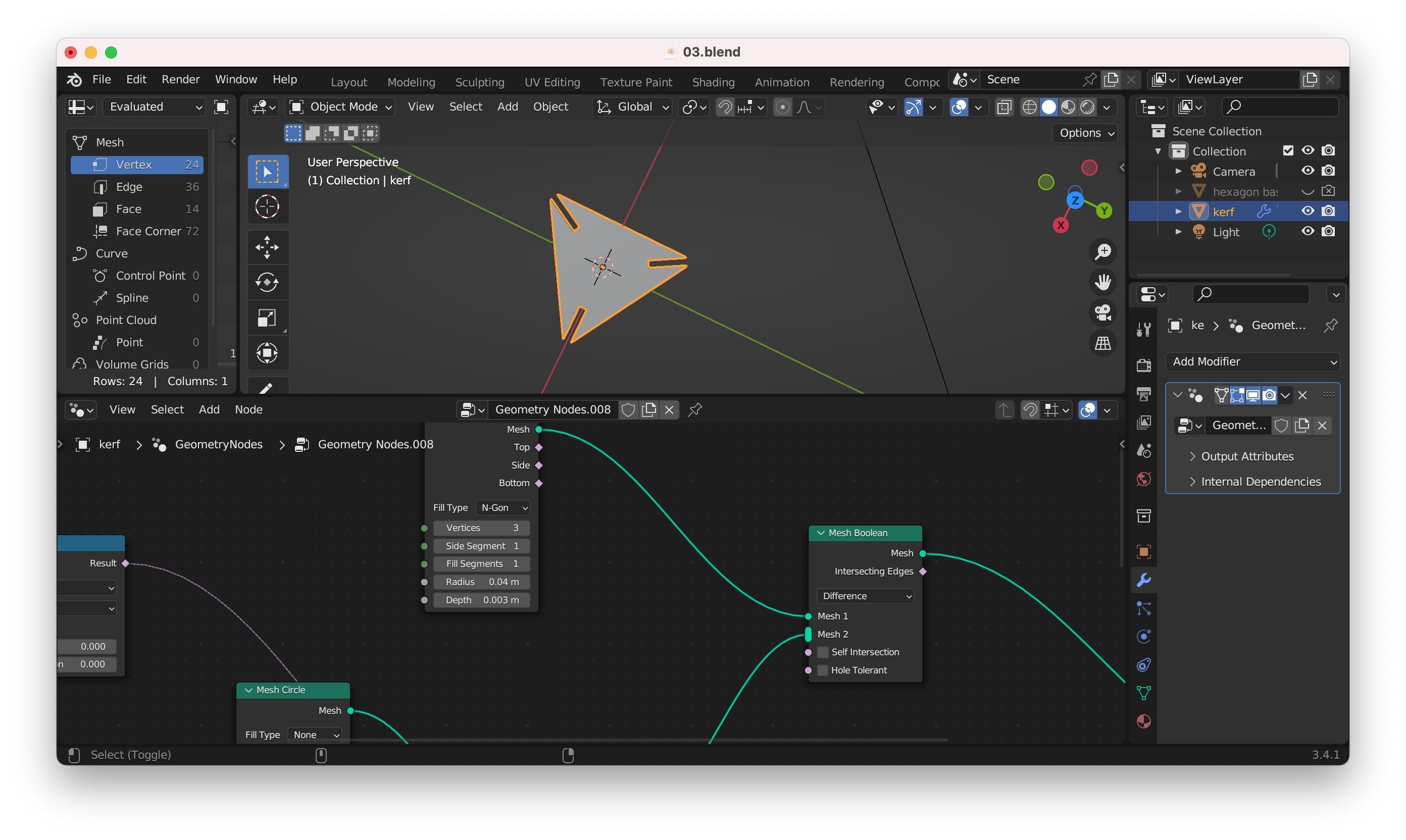
I thought that could be easy to simply use booleans, being the hexagon (or any other shape if we change the number of sides) the object to be cut and an array of rectangles (defining the kerf) the cutting object.So I started to look for tutorials and followed this one that really helped me.
Setting the direction of the array
I then need to point all the shapes to the same origin point in the middle of the shape. So I added NODES that allowed me to point the array to the middle according to an axis.
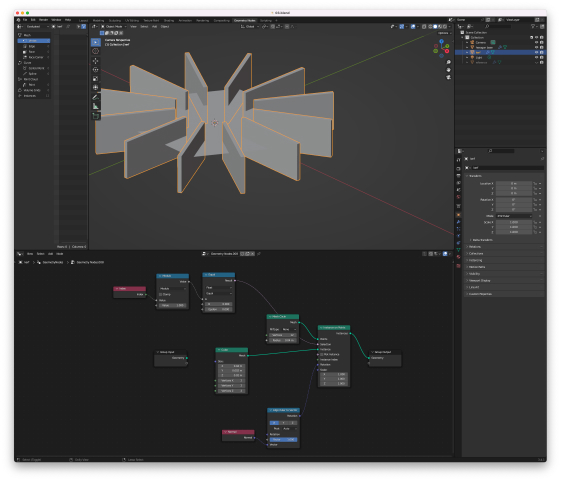
Intersecting
It was not possible (for me at this moment with my amount of knowledge on this) to intersect the hexagon plane with the 3d array, it was giving a weird cut. So I added some depth to the hexagon and it worked perfectly! I can easily change all the parameters of this press kit, including the kerf.
"Make 2D" in Rhino
I first searched for ways to delete the faces of my object, but then I thought there could be other ways, I searched online and saw a tutorial explaining that we could transform 3D objects into 2D to send to the laser machine by using the command "Make 2D", I tried and it worked!
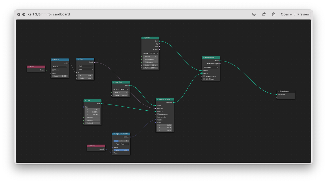
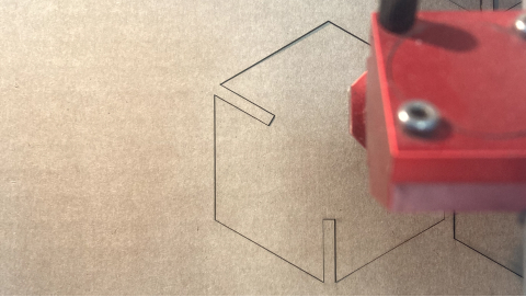
Setting up the kerf for cardboard
According to our tests for the cardboard material the kerf should be 0,2mm (this means that the laser is burning 0,2mm of the cardboard when cutting), so I went ahead and updated my parametric design considering the kerf, and exported my file in DXF.
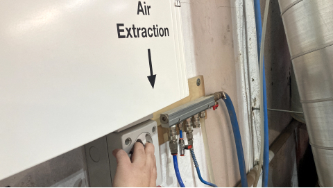
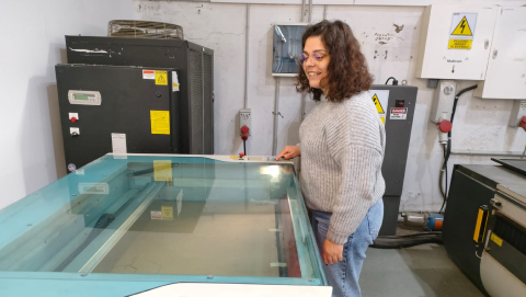
At the laser machine
To start the laser machine I first started the air extractor. Then I turned on the machine (I used the Trotec Speedy 400), and I aligned the focus using the little piece we have there, by moving the bed until it touches the little piece and it falls.
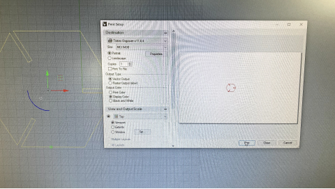
Getting the file ready at the computer
I opened my DXF file in Rhino and made sure the scale was the same. I also made sure I deleted duplicated lines and set the color to red (cut). Then I send the file to print and made sure the settings were correct: paper/cardboard. At the machine software, I defined the following parameters to cut.
Cardboard 3mm
|
Kerf was wrong...
After the first pieces, I realized the kerf was really tight, so after measuring the material again I realized the cardboard I was working with was actually 3,8mm and not 2,7mm! I went back to my Blender file and updated it accordingly. I did the same process as before and updated the parameters.
Cardboard 4mm
|
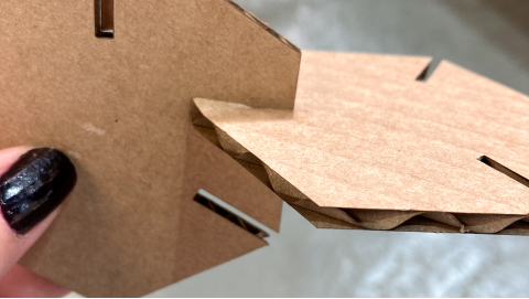
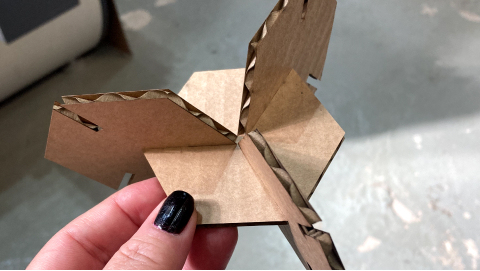
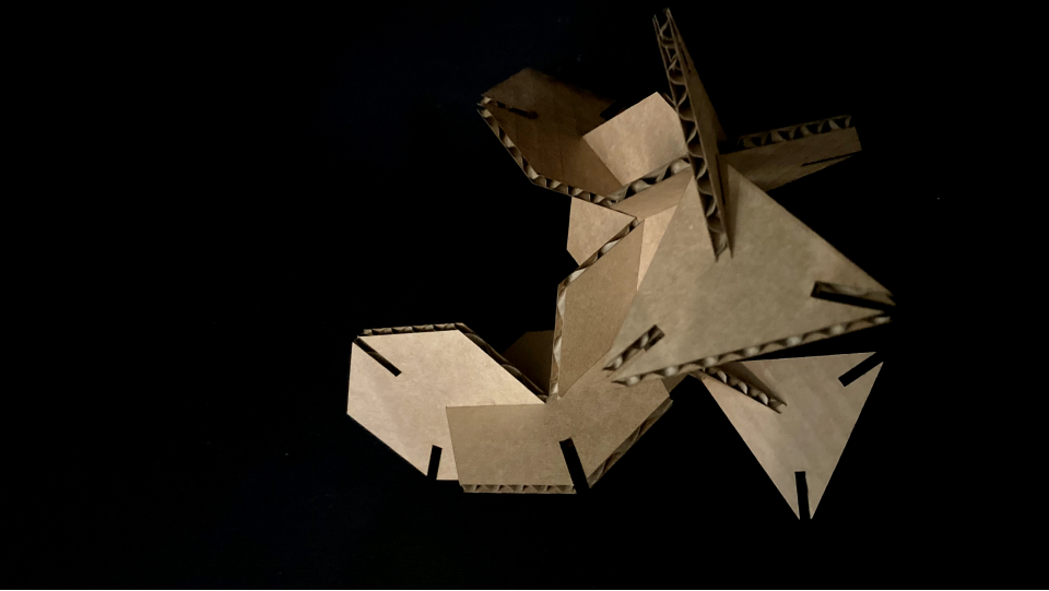
Perfect fit!
After cutting the first 2 pieces I understood the fit was perfect so I cut a few more. After I went to Blender and changed the parameter of the number of sides of the shape to 3 and cut again using the exact same process as described above. So my final kit has triangles and hexagonons as you can see in the photo bellow.
Using the vinyl cutter
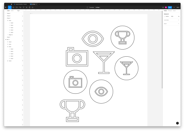
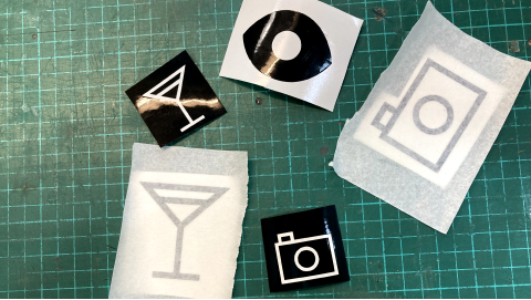
Icons
In the past I have created an icon series - Straw that I really like so I thought about cutting those as stickers. The icons are SVGs so I selected a few in a Figma file and prepared them for the machine.
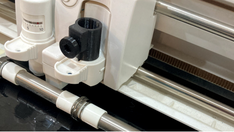
Loading the machine
I started by opening the machine (Silhouette Cameo - vinyl cutter) and pushing the pull down so that the roll is up. In this machine, the vinyl is fed from the front of the machine. While putting the vinyl I aligned the material to the blue arrows on the side of the machine. I also made sure the vinyl is touching the white cylinders of the machine. Then I turn up the pull and clicked "load" in the machine. I also used the matt so that the vinyl was straight.
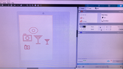
Preparing the file
I started by importing my DXF file to the machine software - Silhouette Studio (I had to convert my original file that was in SVG to DXF using Inkscape). I set up my file size (A4) using the tab on the right side. Then I scaled my . When I was ready I selected the "send" tab to define the parameters of the cut. I noticed some of the shapes were broken in multiple lines, so I removed those (they were duplicates of the icons, but inside a circle, so that might have been the problem). When I was ready I selected the material - vinyl glossy, that gave me already the default parameters for that material I did a test to see if the cut parameters were good (it's good when the cut doesn't cut the paper on the back of the vinyl) and it was.
Vinyl glossy material default parameters
|
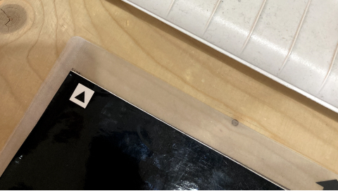
Vinyl stickers
I then sent the job to the machine and just waited! I removed the negative part using the clamp.
→ Design files here
Reflection
I really struggled a lot doing the parametric design in Blender for the first 2 hours, then with the help of tutorials and trying to approach it in different ways I managed to do it. I feel that using geometric NODES is probably quite logical once you are in that flow.
I really enjoyed doing the process at the laser cutting machine and it was really nice to see how fast the machine works! I also learned how important it is to make tests and make sure we have the measurements right.
It was also fun to use the vinyl machine, very simple!
Final project and laser and vinyl cutting)
At the moment I think that the bottom part of my project can be done with wood using the laser cut machien to cut it.