Week 02 - Computer Aided Design
This week covered one of the most interesting topics for me, computer aided design. I have been professionally involved in CAD for over 7 years now. SolidWorks is my go-to, and the reason I chose it because it was the only available CAD software at my university. I have started using SolidWorks back in 2014, but only for university assignments. In 2016, I decided to become better at it, so I went through advanced tutorials and YouTube videos, then hopped onto any freelance opportunity. In 2019, I received the professional SolidWorks certificate 'CSWP' which helped me learn more about the software and how to manage large engineering projects.
This week introduced us to 2D and 3D computer design. I was familiar with most of the topics and the suggested software, however, I would like to pinpoint some of the things that I found most interesting, also, to refresh my memory too.
2D and 3D Modelling
2D Modelling
I have worked with vector files before; I have briefly used Adobe Illustrator and InDesign. But I have never converted raster files to vector files. Also, some of the only times I used vector files is when I converted a viewpoint of a 3D model on SolidWorks to a SVG file for a laser engraver machine. But our instructors got it to my attention that 2D CNC machines follow the geometrical line of a vector image for precise cuts or engravings.
Regarding image formats, I have never paid attention to the differences between PNG and JPG files except that PNG are transparent. Well, I was never in a situation that needed me to understand the difference. But in this Fab Academy cycle, it is important to understand each to at least help us manage image sizes when uploading images to our repositories. Now let's talk about GIF for a second, I always thought GIF format only included those short videos found on social media, that's a first. Another cool thing about the word GIF is the never-ending debate whether it is read as GIF or GIF. Now you are reading it as GIF or GIF, let's check again, GIF or GIF, you did it again, stop smiling! If you are interested to know the verdict, check this article.
Another tool that I have found useful is picsvg, this would come in handy especially when laser cutting or engraving. This will definitely save up so much time when/if I'll be engraving designs and patterns on my final project. Talking about engraving, the following is an example image of creating an DWG file from SolidWorks which can be sent directly to a laser cutter machine or converted into a SVG file then sent to a laser cutter machine.
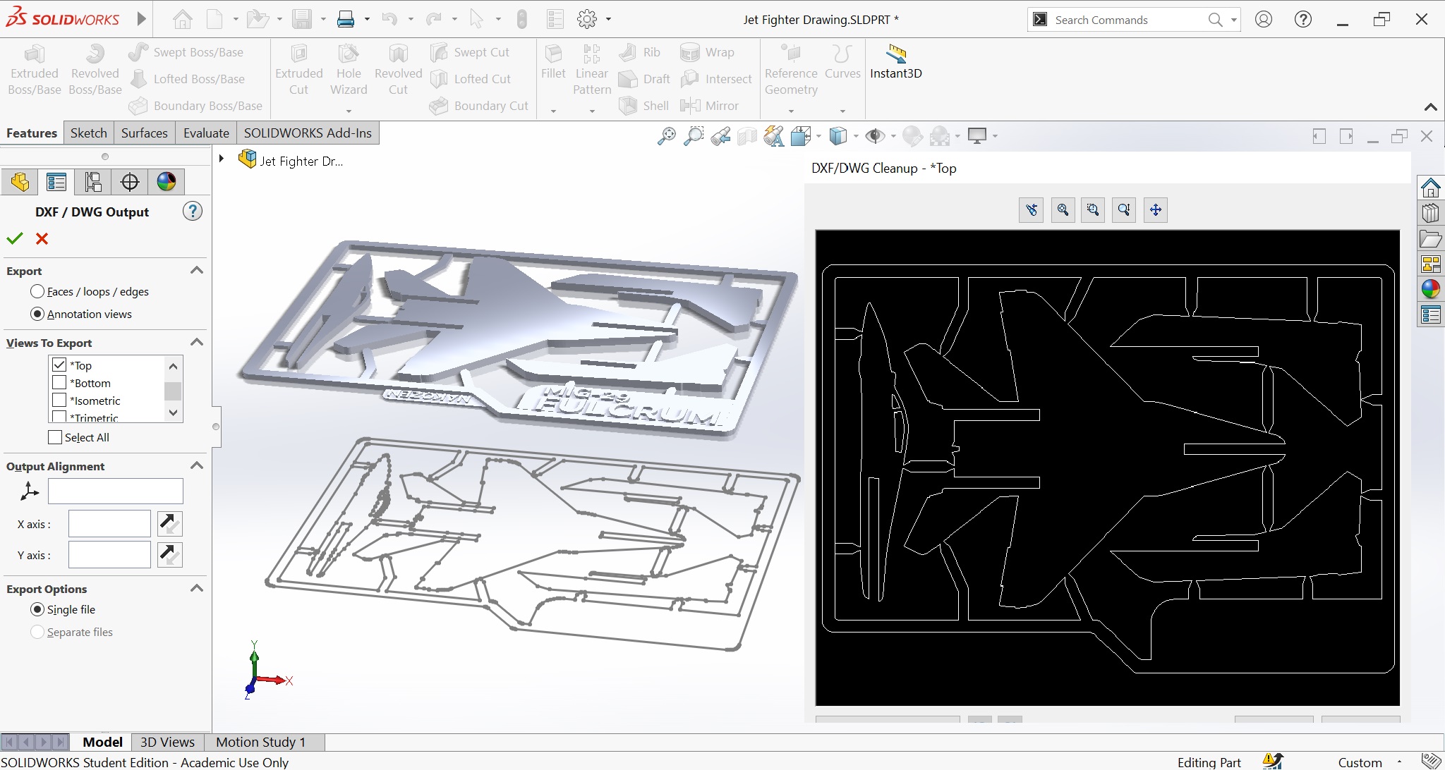
The model in the above image is the MiG-29 Jet Fighter Kit Card from Thingiverse done by the user Nakozen. I downloaded the file in an STL format, then converted it into a 2D drawing, then exported the drawing as a DWG file.
3D Modelling
The 3D modelling world is a never-ending world, there is no best software, each software is intended for a certain application. But before getting into the software, I was introduced to NURBS modelling, which stands for Non-Uniform Rational B-Splines modelling, to my understanding, it produces very smooth surface for very complicated geometry. To my advantage, SolidWorks does contain NURBS modelling, so that's a plus.
Parametric design is a process based on algorithmic thinking that allows the expression of parameters and rules that together define, codify, and clarify the relationship between design intent and design response. And that is my friends the definition of plagiarism because I copied that sentence word by word from my lecture notes. In layman's terms: Parametric design is a way of designing things using a set of rules and guidelines that are based on computer algorithms. So, when designing an object, the features of that object are related and connected to each other. Changing a parameter can change everything, which is great if desired.
What excites me the most about this course so far is that I am understanding the science behind the tools and software we are using. This makes it much easier when I actually use the tools and is great for trouble shooting. For example, if a tool in a 3D software is not working as I am imagining it to, with the proper knowledge I can do the following:
- Assess if my geometry/curves are correct
- Try play with the parameters of the tool based on knowledge, not trial and error
- Abandon this specific design detail because it was wrong
Whereas before, I used to spend so much time looking for a solution to a problem, realizing that the tool I am using is not the right one to begin with. We were introduced to both 2D and 3D software, some of them are:
- 2D Software:
- Inkscape
- Picsvg
- Qcad
- 3D Software
- Rhino Grasshopper
- Fusion 360
- Onshape
- Blender
- FlatFab
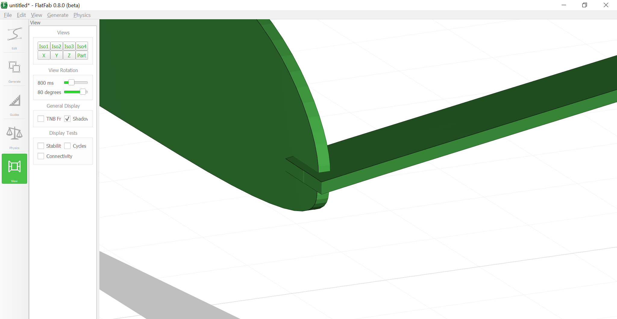
Although SolidWorks is the software of my choice, FlatFab got my attention. FlatFab is a 3D software in which it allows you to create 3D structures based on flat components. I hope this made some sense, if not, check the following image.
This software will be of a great addition to my skill-set as it will help me to create skeletal structure for anything, mainly an aircraft. At least this is my intention of why I am using it for now, this could be of a great benefit to help me with my final project, which is a drone btw. I can create a light-wight rigid structure to help me house all the components inside.
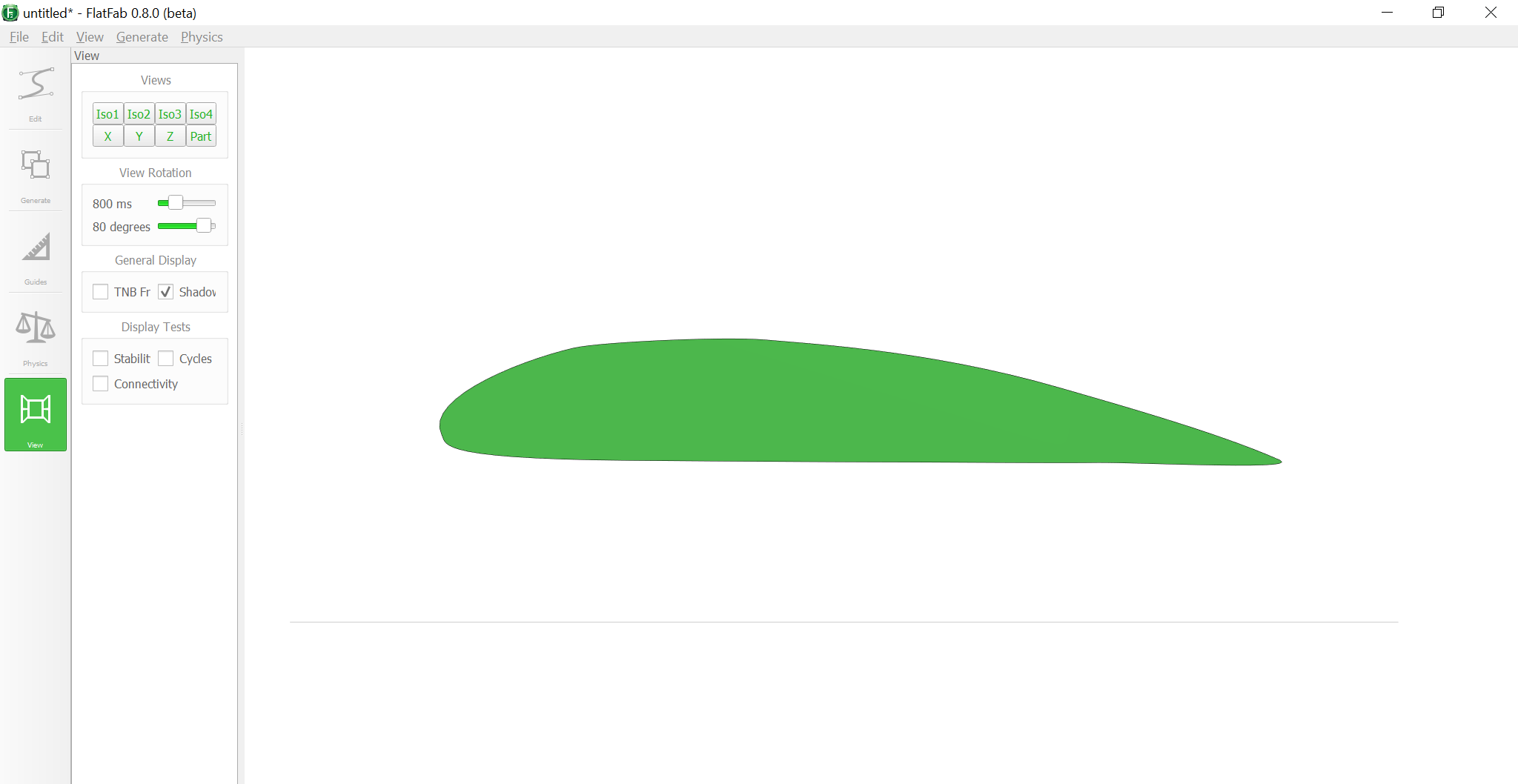
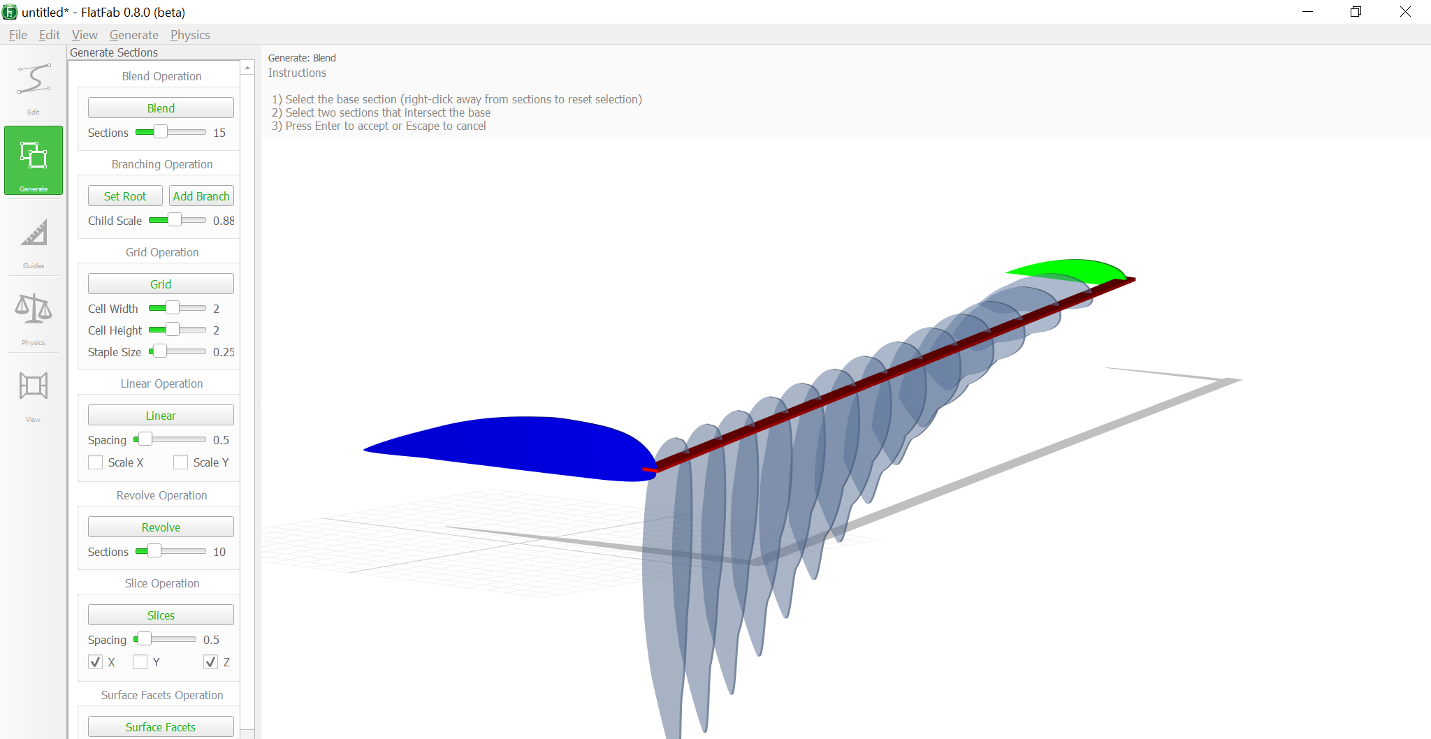
I have checked this tutorial, however, the tutorial is done on an older version on the software and it was a bit unusable. Regardless, I tried to grasp the concept by creating a skeletal structure of a tapered wing.
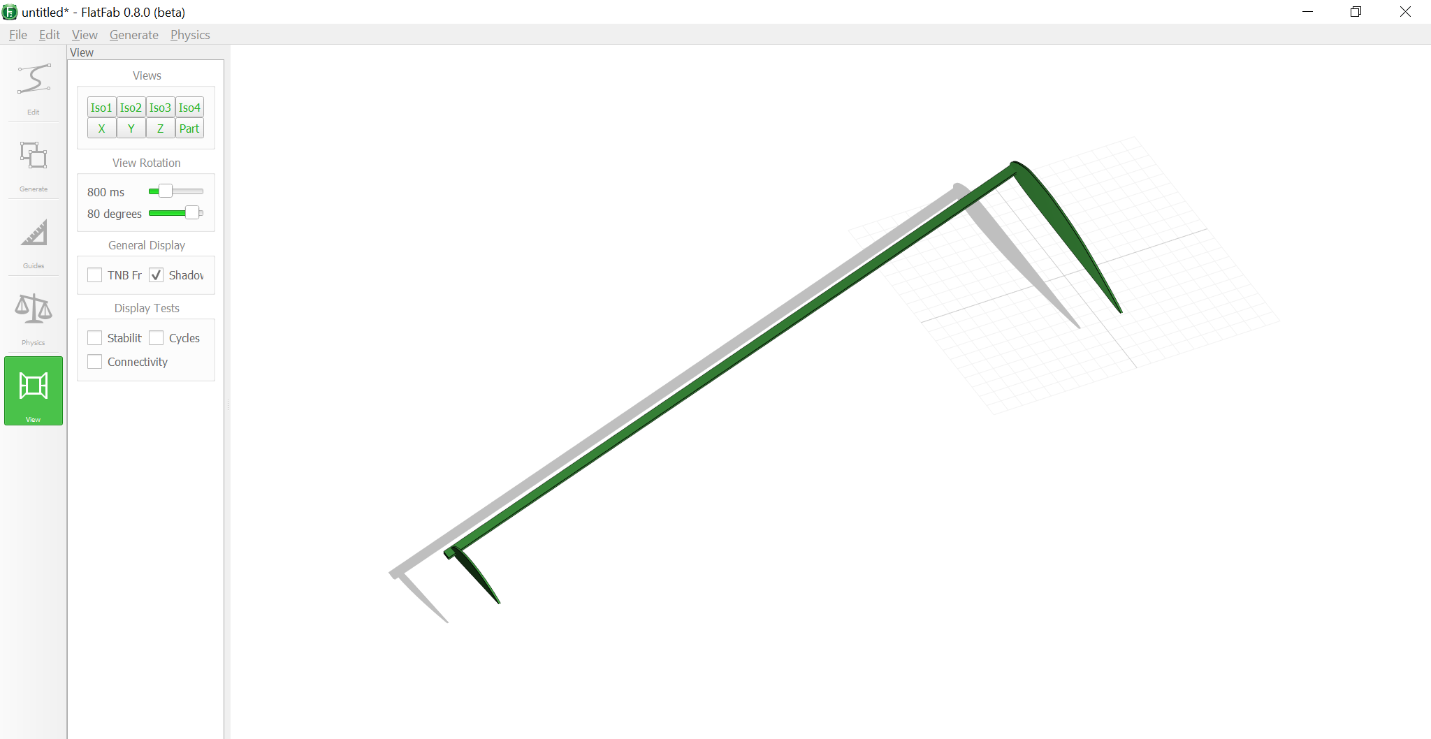
Here I started by drawing an approximate airfoil shape. Afterwards, created a front wing spar and a smaller airfoil towards the tip.
I went to the 'Generate' tab and used the 'Blend' feature to create the remaining airfoils in between.
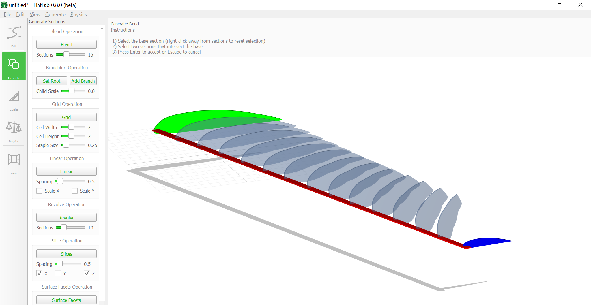
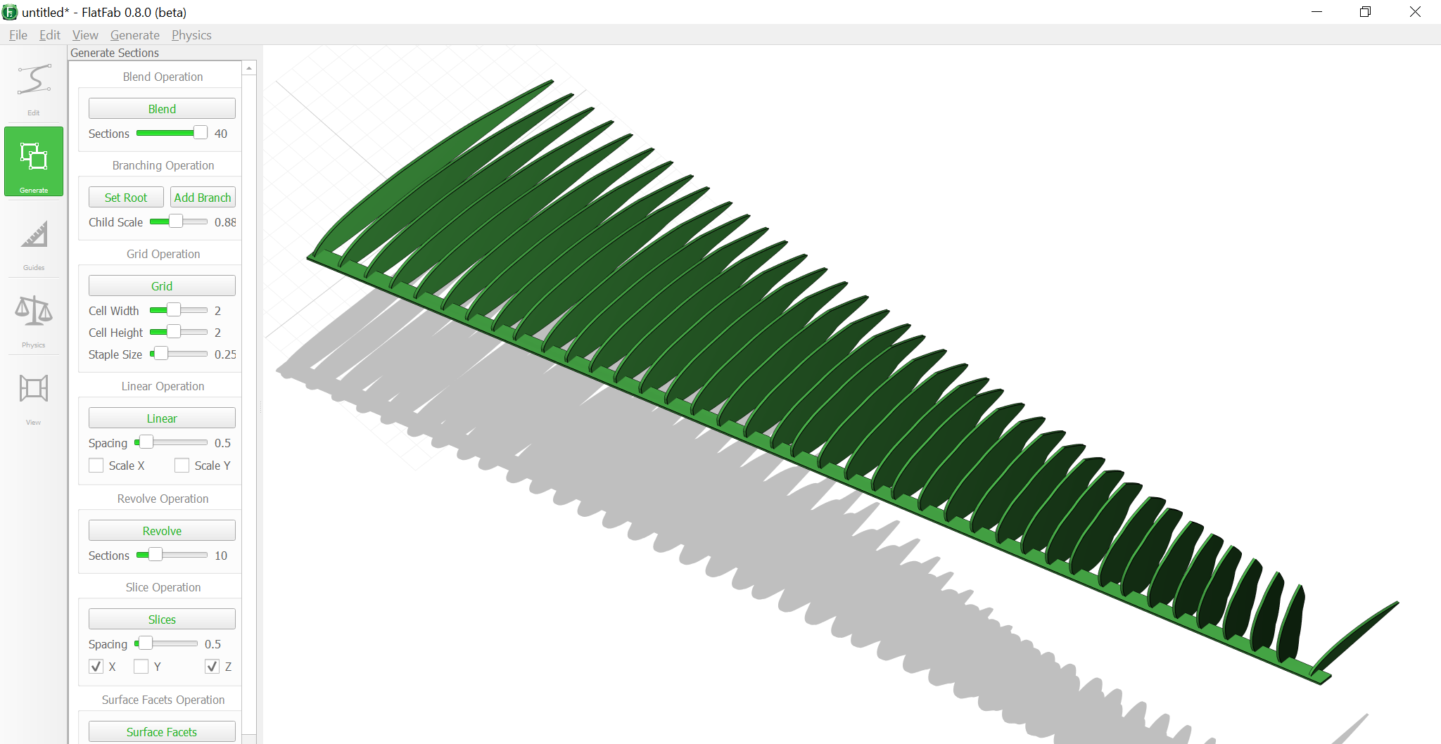
For some reason it twisted the profile, I do think the reason was due to the root airfoil not being in proper contact, so I fixed it as follows.
Again, the issue persisted, but I accepted the failure because it looked cool ether way.
The software is interesting and is a great tool for designing objects, toys, ideas, or anything as a matter of fact. However, I am abandoning it for the following reasons:
- The software does not produce accurate measurements. In my scenario, I need components with the accuracy down to the millimeter.
- The software is not super user friendly, certainly I did not give it enough time, however, it is a bit confusing to have a 3D software that does not allow you to choose a plane to start you drawing.
- For some reason, my laptop was struggling running the software, it did not struggle this much while running SolidWorks, which doesn't make sense.
I understand that the applications that I am looking for are not the intended use of this software. On the bright side, with some Google magic, I was able to find other software that could benefit me more. Thanks to FlatFab, it was the starting point of my search. I have found Wing Help which help users to design and create wing structures for model RC planes, unfortunately it is not free. Also, I have found an open source nesting software which is great for laser cutting, it is called Deepnest. Both software could come in handy if I absolutely needed to design a wing, but for now, I will settle on SolidWorks.
Another interesting topic was Generative Design and Topology Optimization. Generative design is a design approach where the design process is guided by algorithms that use design criteria and constraints specified by the designer, to generate a large number of design options. The designer then selects the best solution from the generated options. Unfortunately, SolidWorks does not have generative design, only Fusion 360, and the license is pretty expensive.
Where topology optimization is a computational method used to find the optimal distribution of material in a design, given certain design criteria and constraints, such as strength, stiffness, weight, and others. The method uses algorithms to iteratively remove material from areas that do not contribute to the design criteria until an optimal solution is found. This approach allows designers to create designs that are lightweight and efficient, while still meeting their functional requirements.
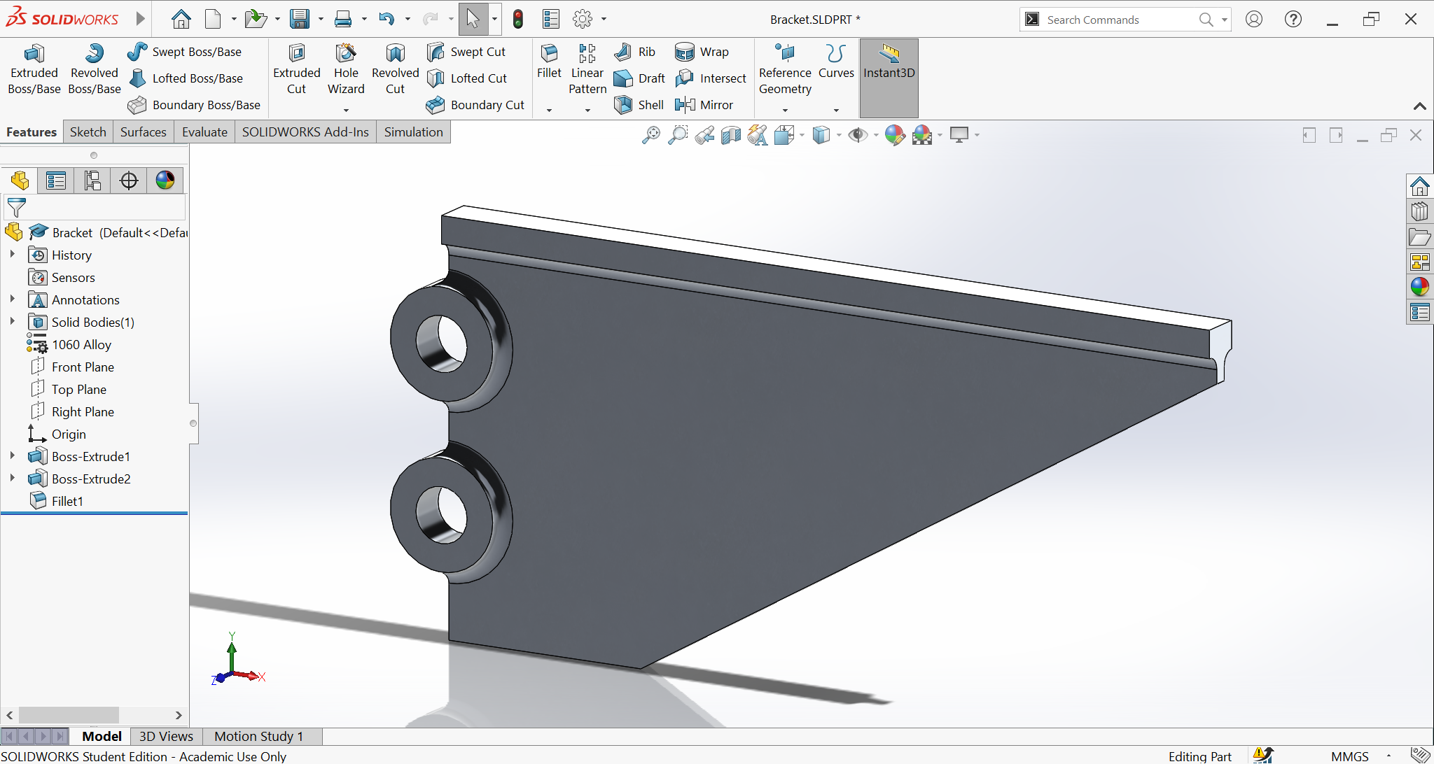
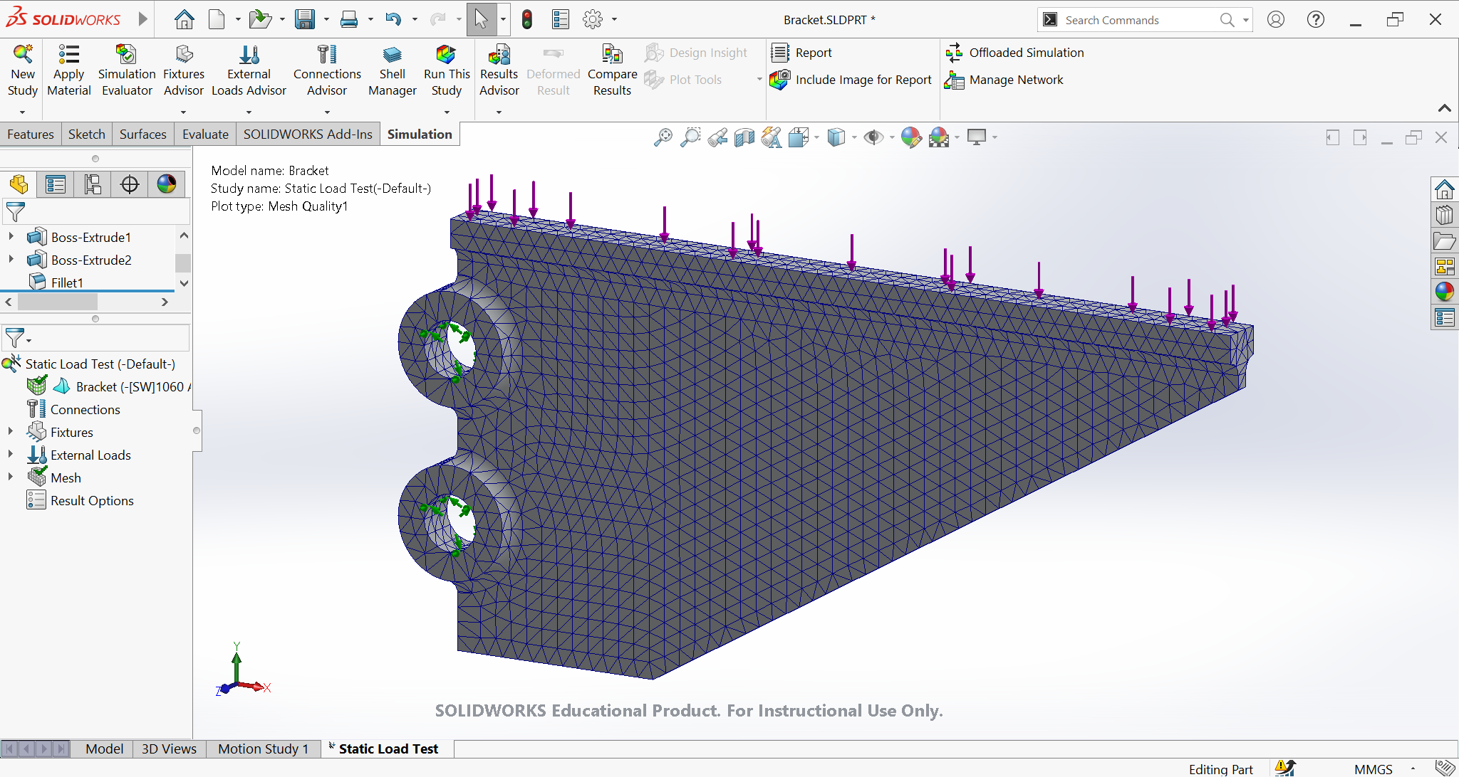
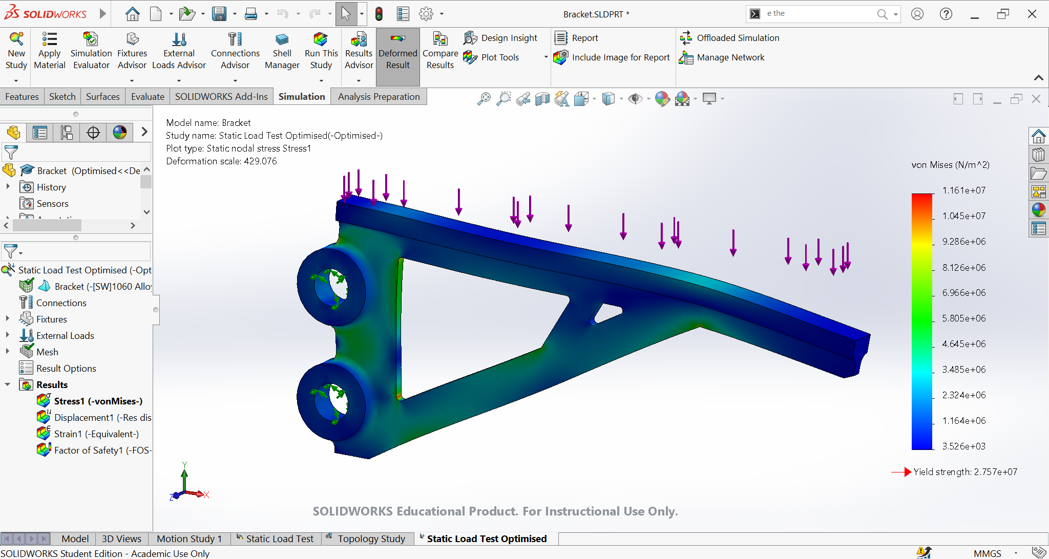
Guess what! SolidWorks has that option, and the following is an example of a bracket that is optimized through topology optimization. Started by creating a simple bracket with a material of 1060 Aluminum Alloy.
Went to the FEA Simulation tab, fixed the bracket from the holes, added a load of 250N on the top surface, then created a mesh.
I ran the simulation and here is the result.
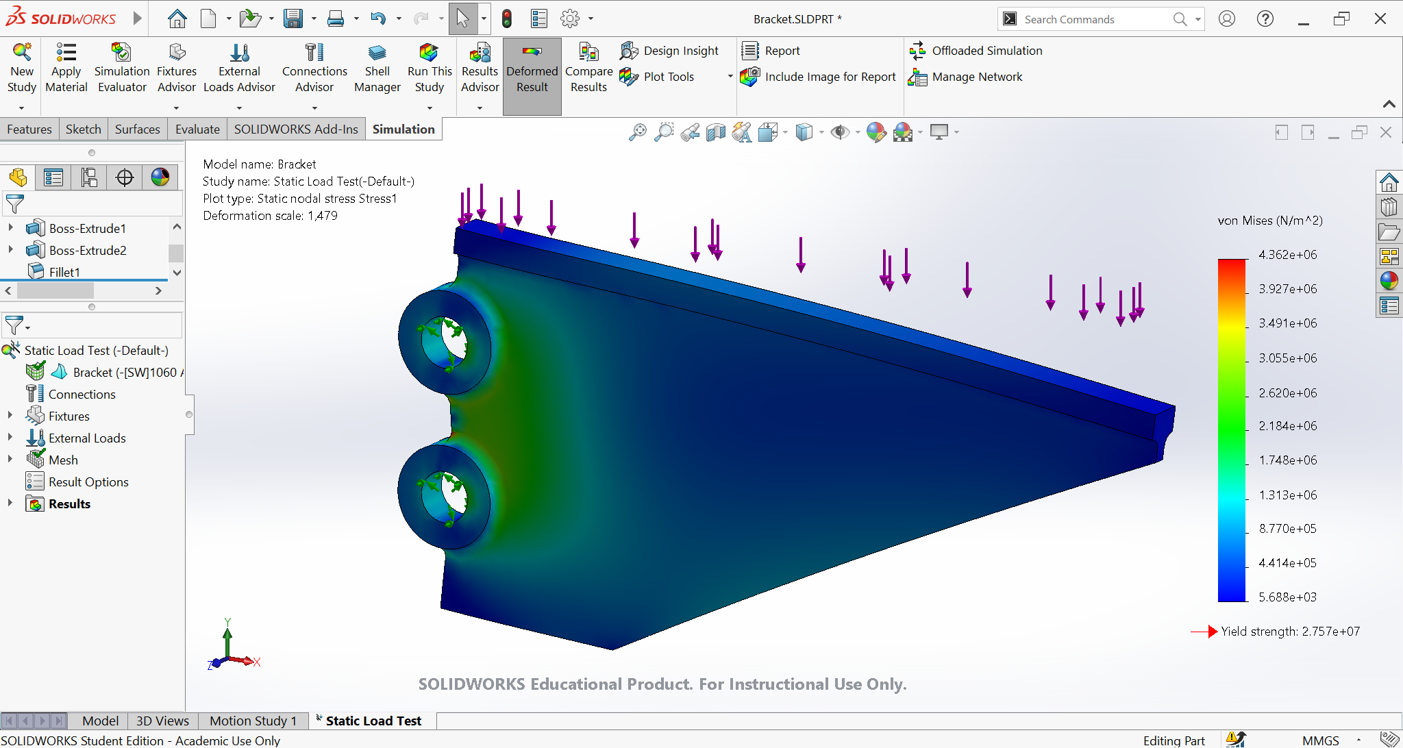
Now this simulation will be the base for the topology optimization. The factor of safety is about 6.3, meaning that the first failure will occur at 6.3 times the load I applied, which is about 1575N. There is definitely room for improvement, so let's remove more material. I used the same exact model with the same exact settings; however, the study requires additional information: My goals and constraints where the best stiffness to weight ratio, I also asked SolidWorks to try and reduce the bracket's mass by 40%. Afterwards, I added some manufacturing constraints including: some preserved regions so the code doesn't subtract material from there, and a plane of symmetry, in case I wanted to cast the bracket.
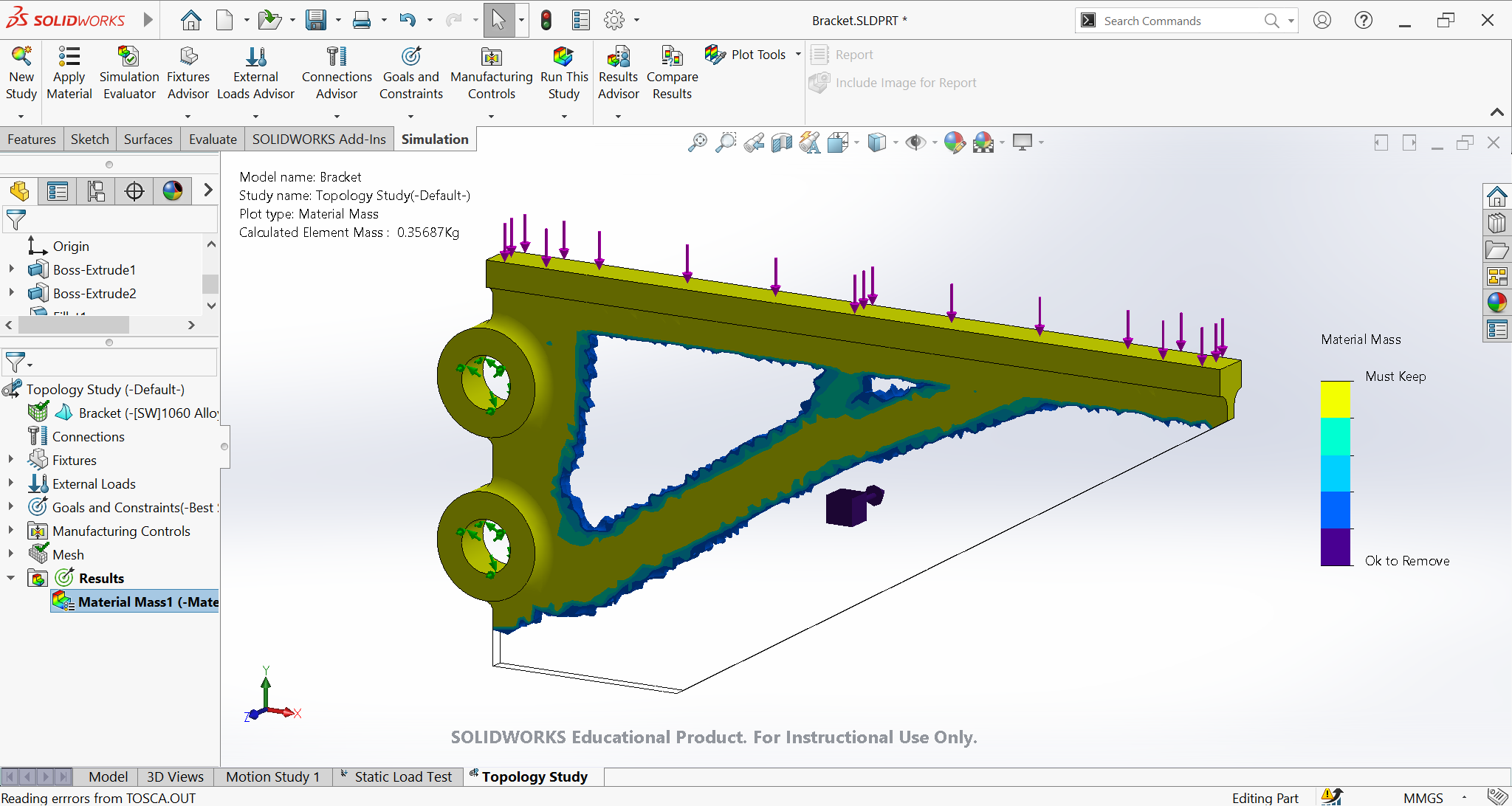
As seen in the above image, All the yellow areas are the places where material must be there. What I can do is use the result as a template then remove the material myself to get a cleaner design.
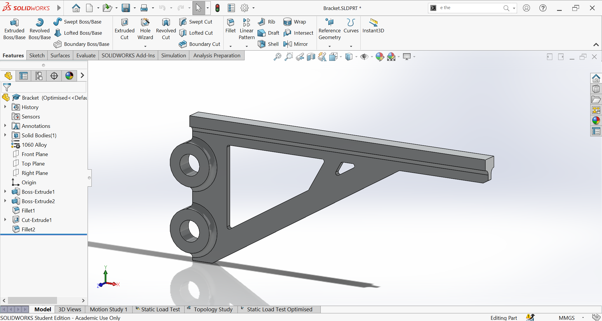
After that, I ran another FEA simulation with the exact setting as before, SolidWorks provided the following results.
The above simulation also provided a factor of safety of 2.4, meaning the optimized design will fail at 2.4 times the load applied, which is about 600N. Yes the max force was reduced, but we saved about 40% of the mass, so if this bracket is used as a shelf bracket, the design is perfectly fine.
Experimental Design of the Final Project
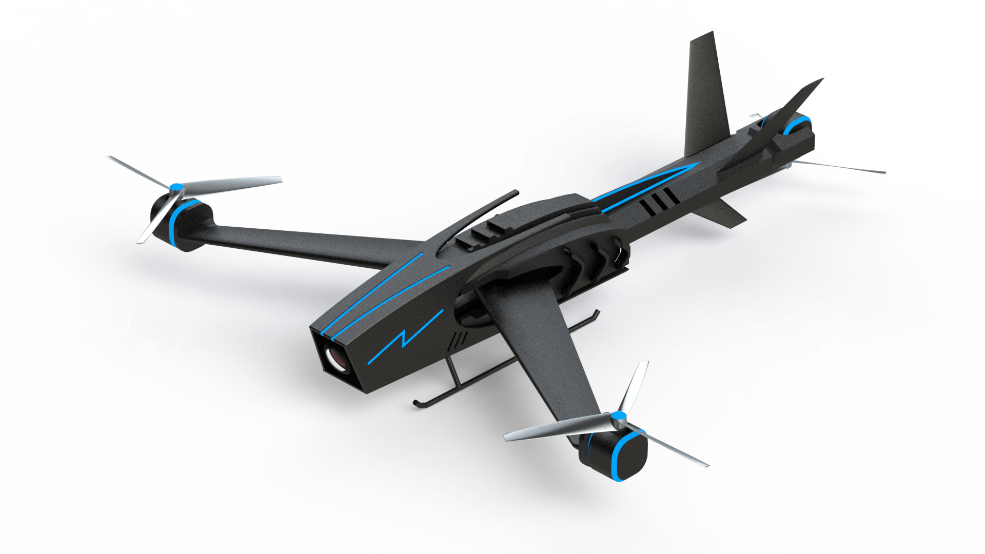
As discussed in Principles and Practices, the drone project will serve as a platform for more drone designs in the future, to serve governmental institutions such as police, ambulance, and fire departments. Having the tricopter design with the forward swept wings, the drone can transition to forward flight which results in superior maneuverability and increased efficiency in each flight phase.
However, due to the sheer size of the project with so little time, the scope was reduced to create a tricopter that can perform basic manoeuver including hovering, pitching, and yawing. You might ask, I have missed the fourth manoeuver which is rolling, it is quite difficult to achieve this with a 3 bladed drone without added complexity. The tail rotor would require a servo to rotate the tail assembly, which requires a hinge, gears, calibration… you get the gist. With the three chosen manoeuver, the tricopter will be capable to move anywhere.
As seen above, the scope of this week was to build a 2D and a 3D concept of our final projects. I would like to show you briefly some of the steps that I took to come up with the wooden structure of the model. But before I start, fun fact: I did not model the electronics for the following reasons:
- Not enough time
- Too much unnecessary details
- I wanted to focus on the gem of this week's assignment, the structure
I got the files from GrabCAD which is the heaven for all CAD users since you can find everything on it. The components I used are linked below:
So, this leaves us with the structure alone.
First things first, I wanted to figure out the cheapest way to manufacture the project so I can base the design on it, which is wooden sheets. That is why I was excited to use FlatFab, however, it disappointed me, still a good software though, but not my jam… okay the issue is from me, I was not ready. Regardless, I started to draw the concept on a paper to have an idea of what I am dealing with.
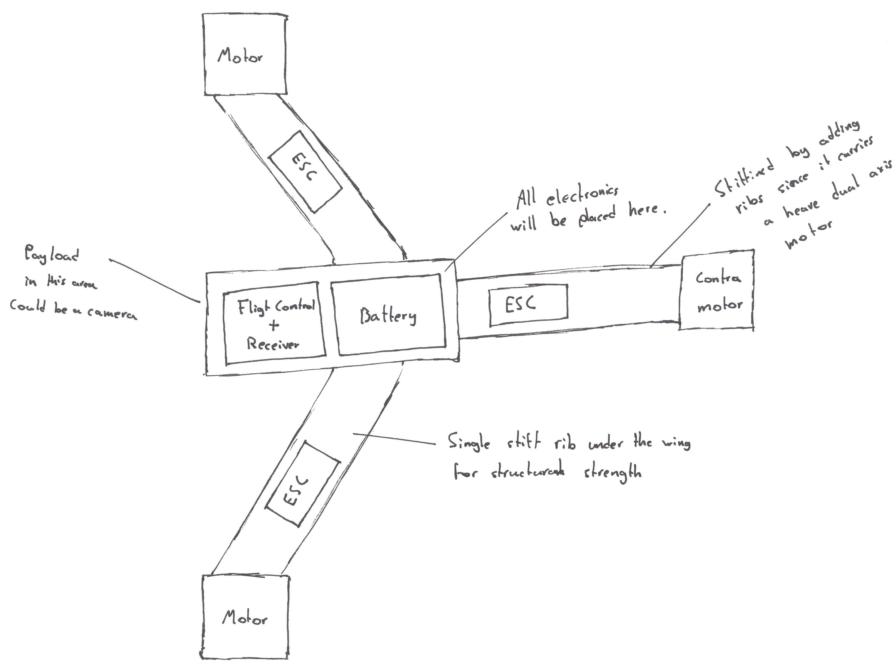
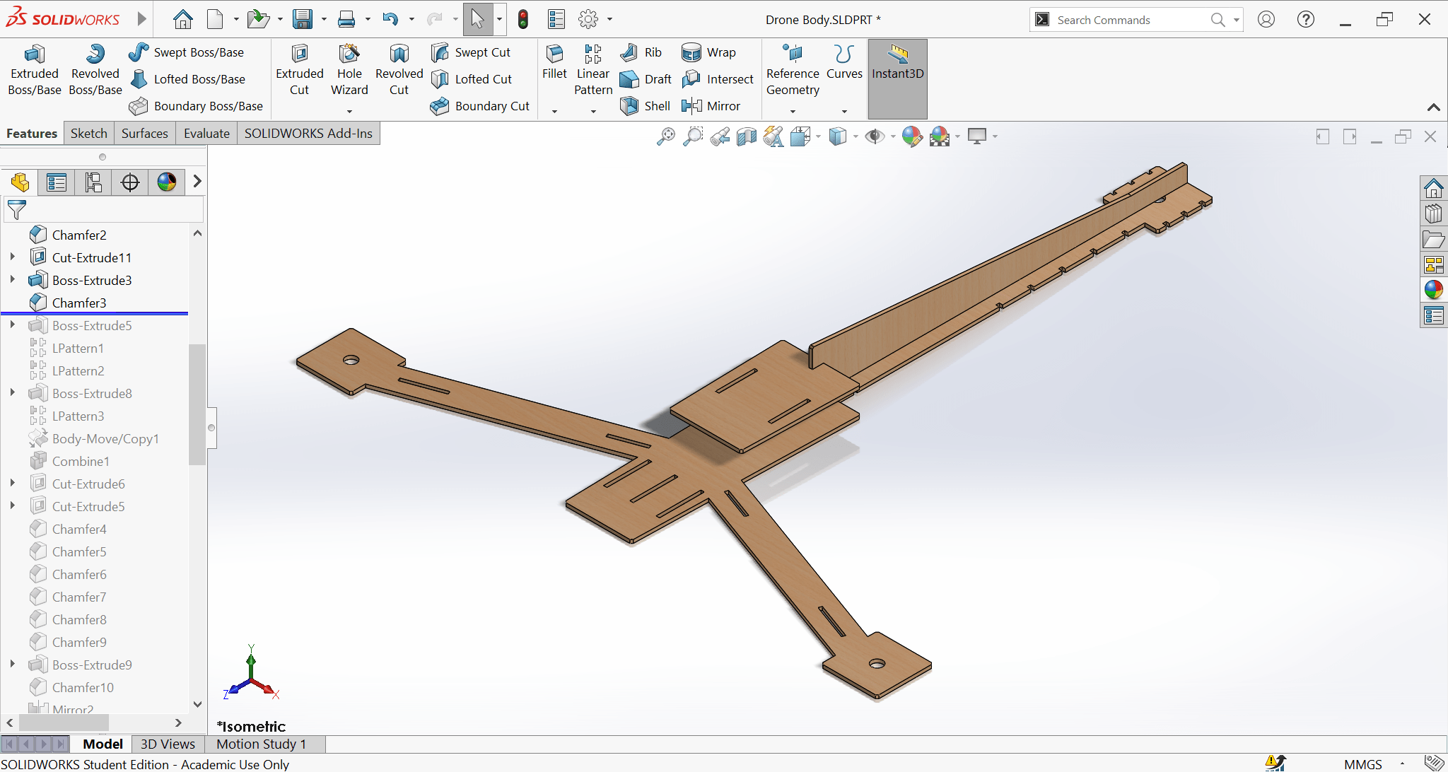
The only purpose of the sketch was to organize my thoughts, or at least to help me imagine the 3D structure. Once I have an idea, I usually build as I go, this journey started by creating a 2D sketch.
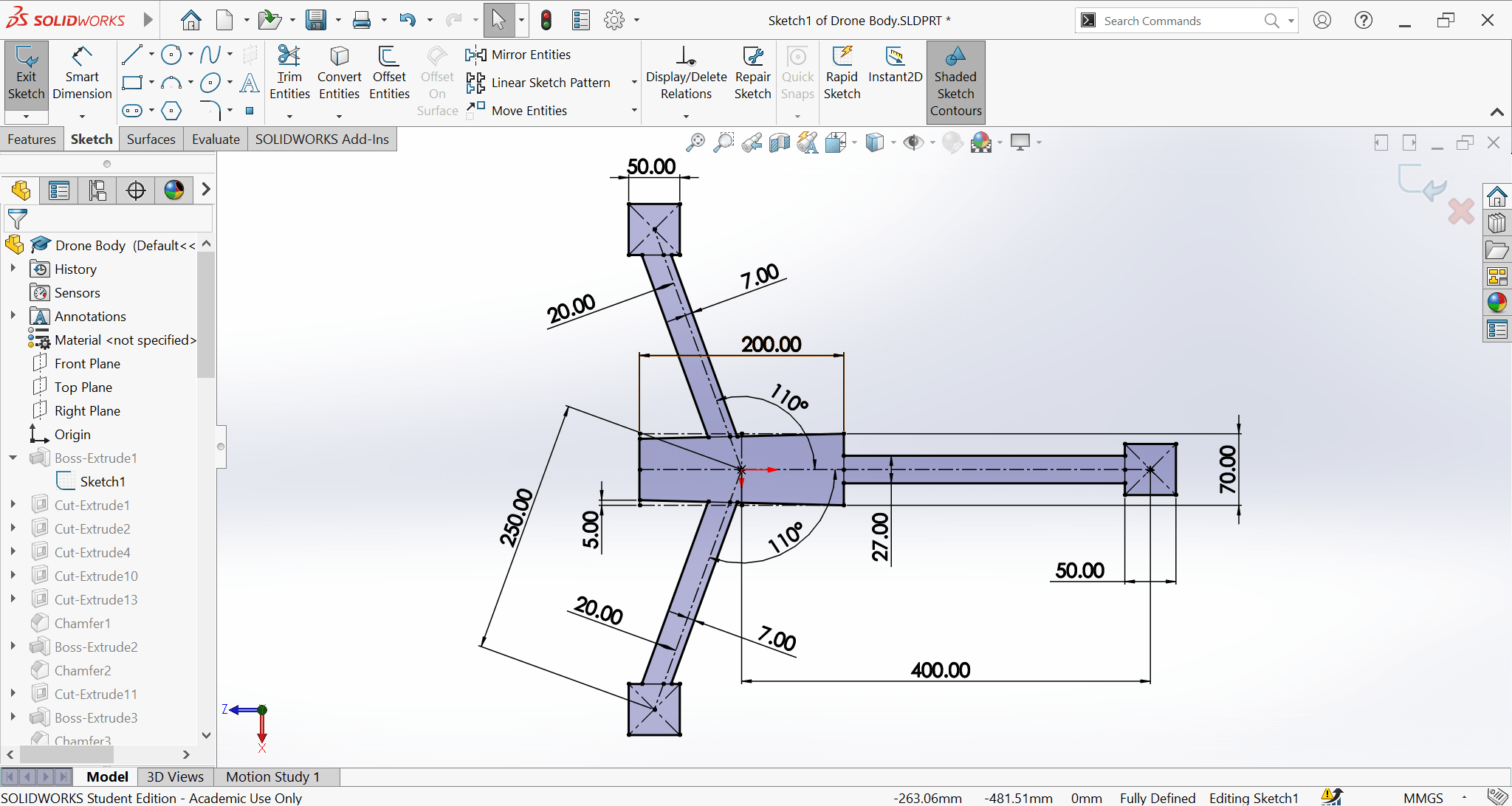
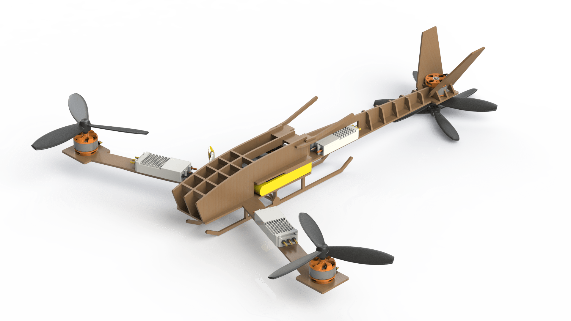
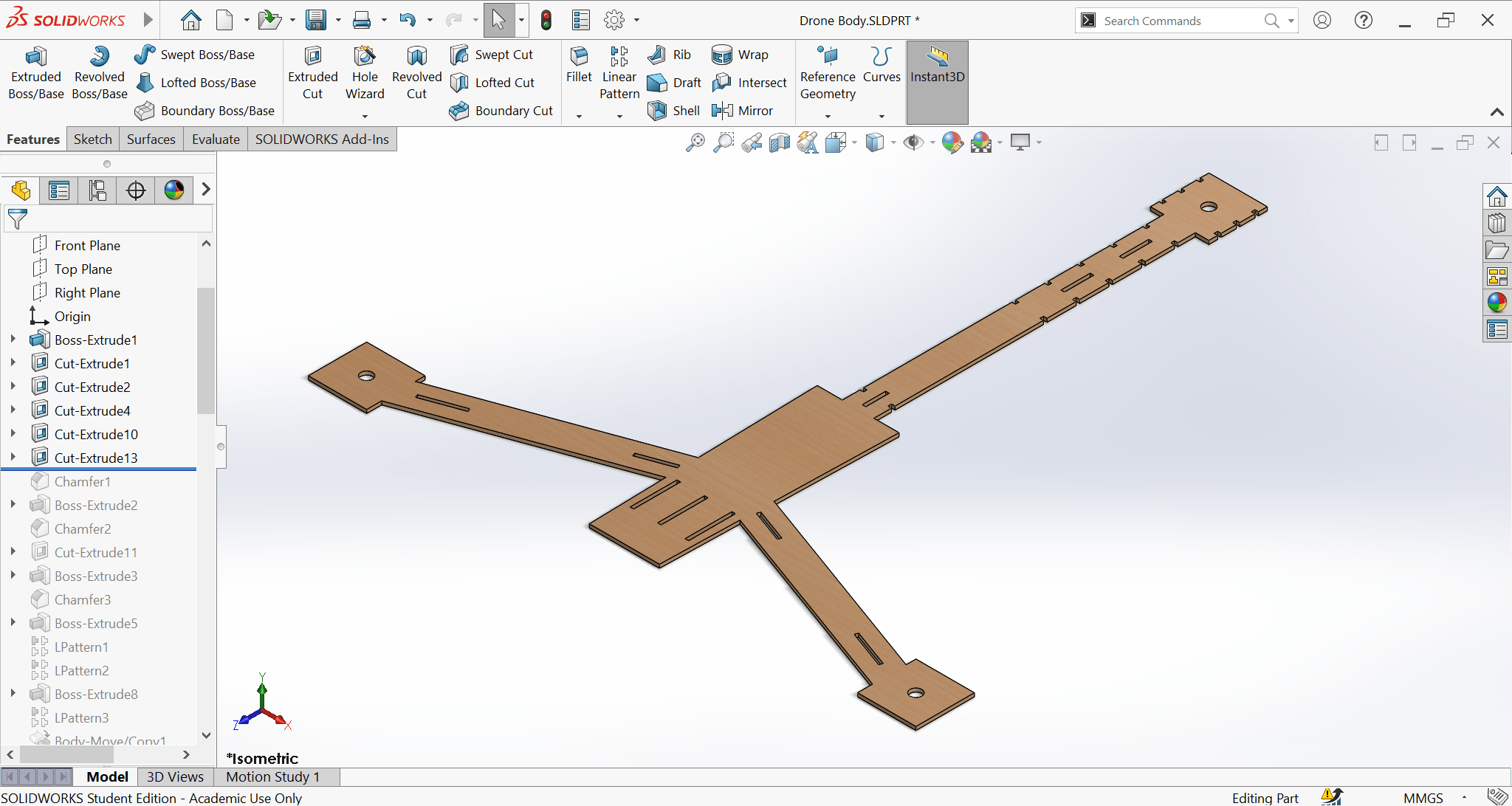
Then extruded the sketch to a 3D wooden slap, then added holes for the structure. I did not decide on the placement of the holes initially, a lot of them were added later as I was progressing with the design. I like to keep my tree history clean and tidy, so whenever I figure out a new place of a hole, I just go back the timeline then added. It appears as if I already new all hole placements, but no, I do it to keep the history logical.
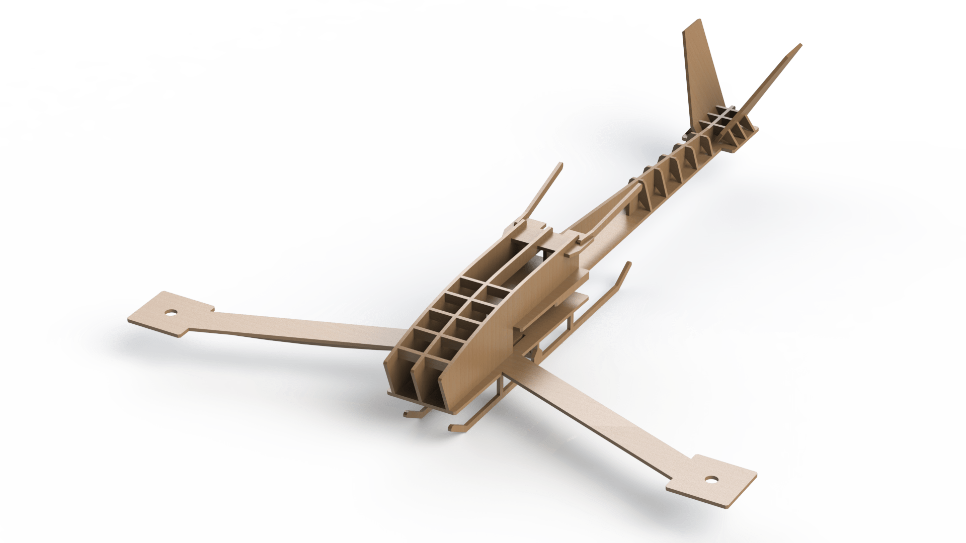
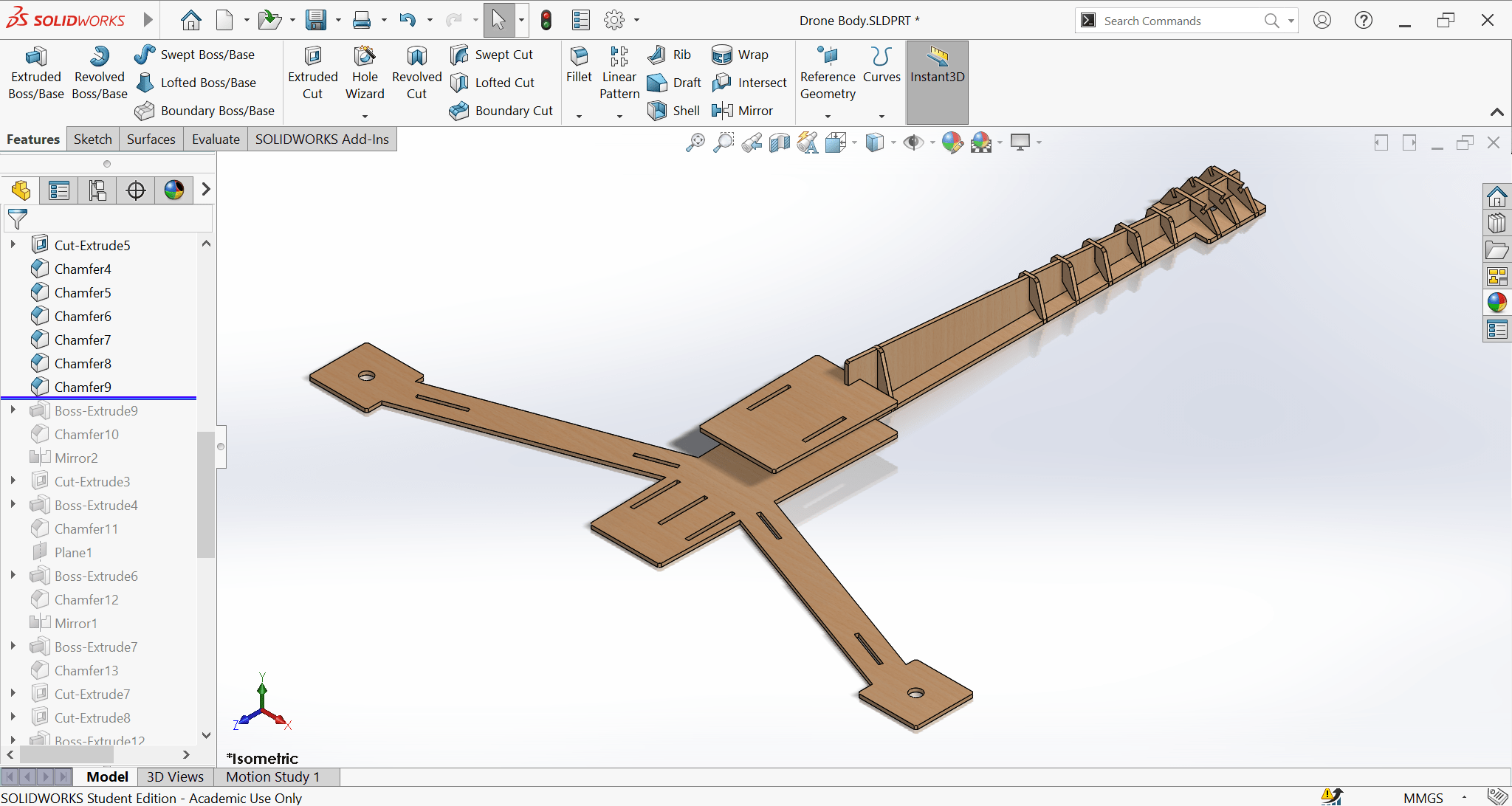
Afterwards, I added a tail structure for strength and a platform above the battery.
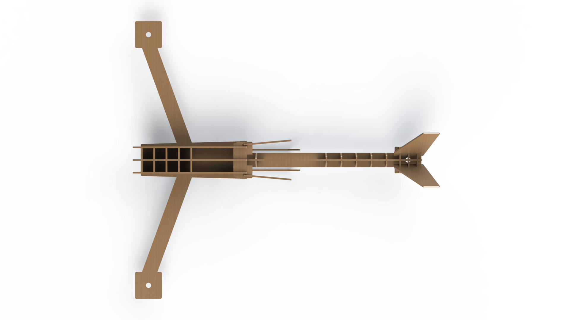
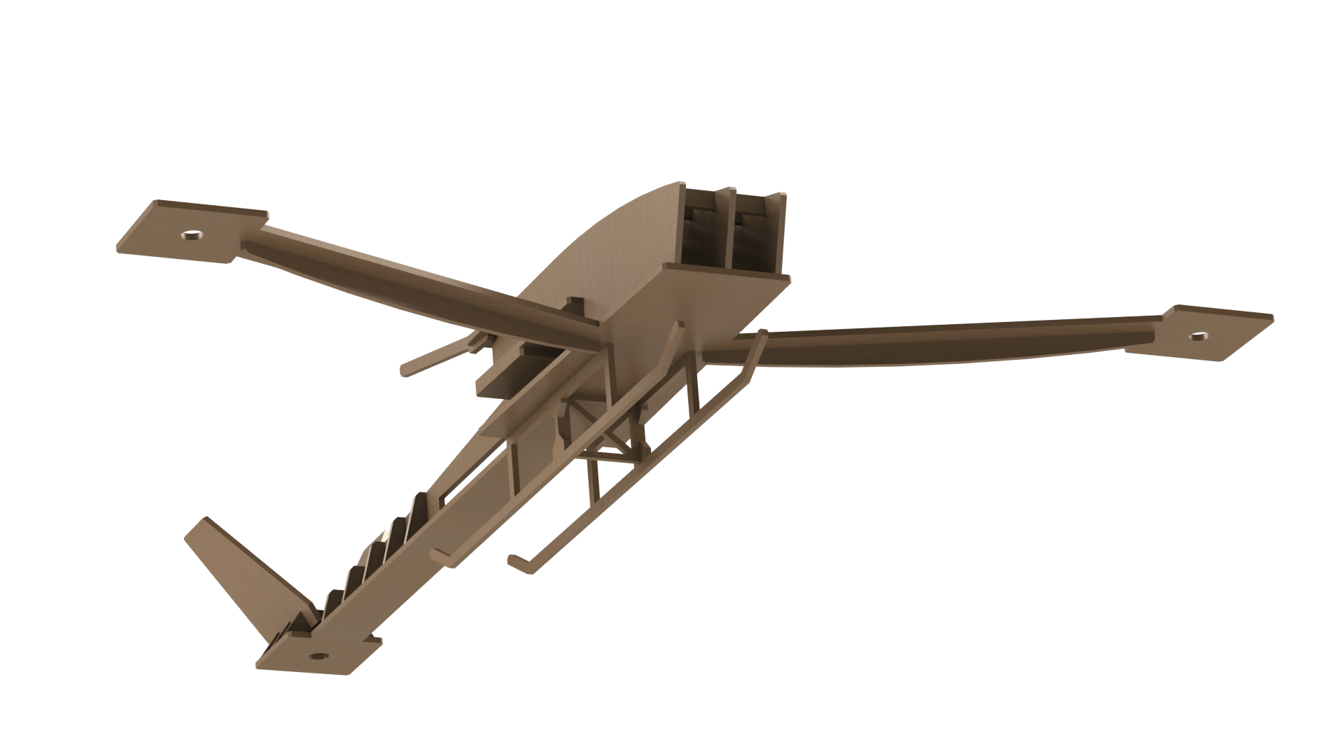
Here, you can see the ribs, they were added to strengthen the structure. Two of them would probably have been enough but it looks cooler this way.
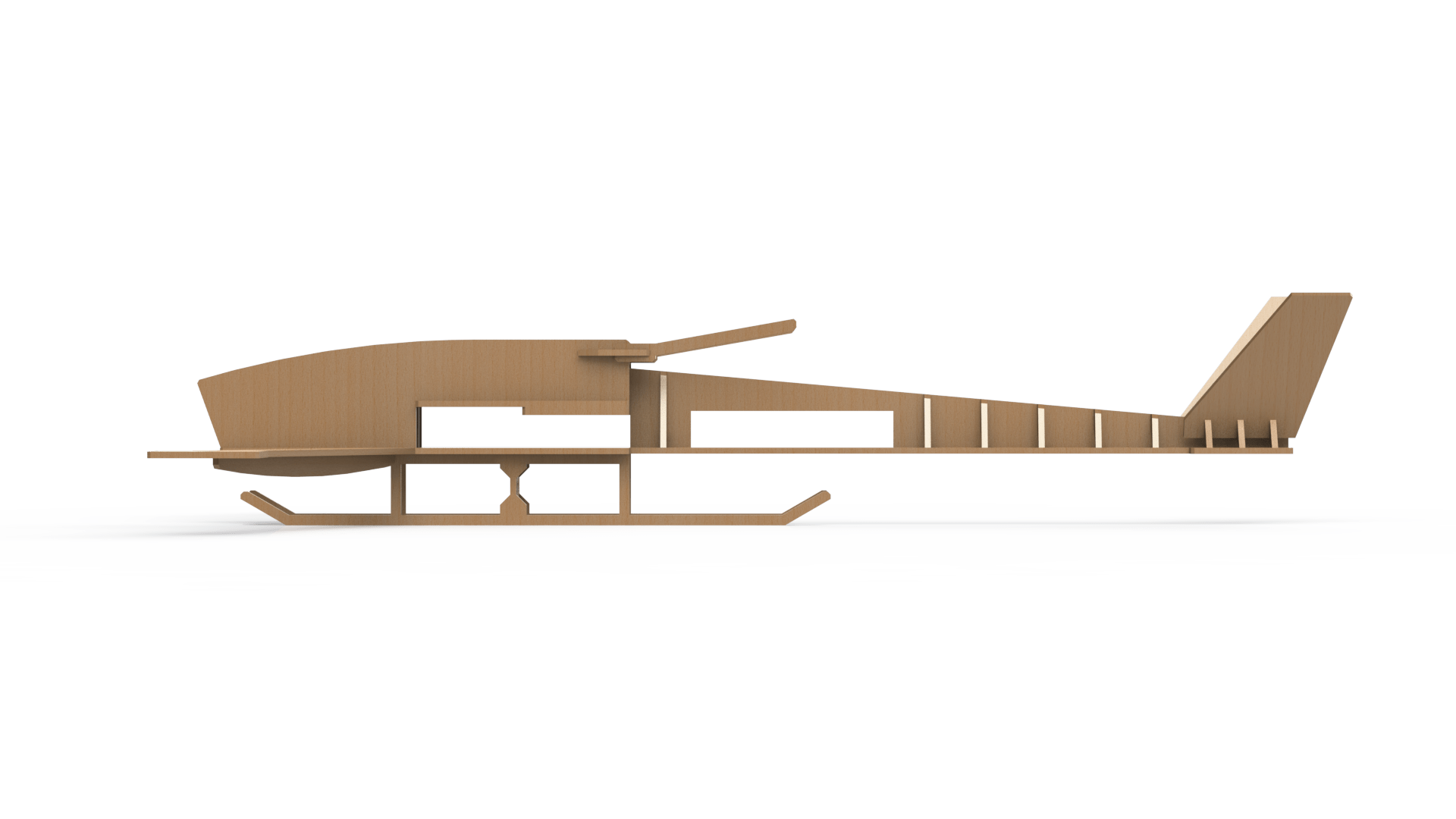
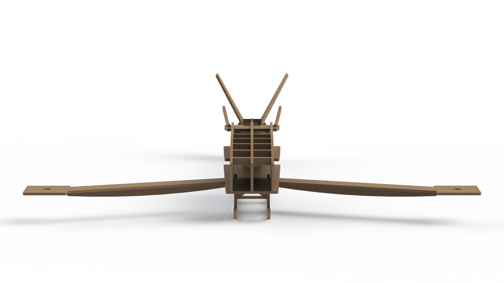
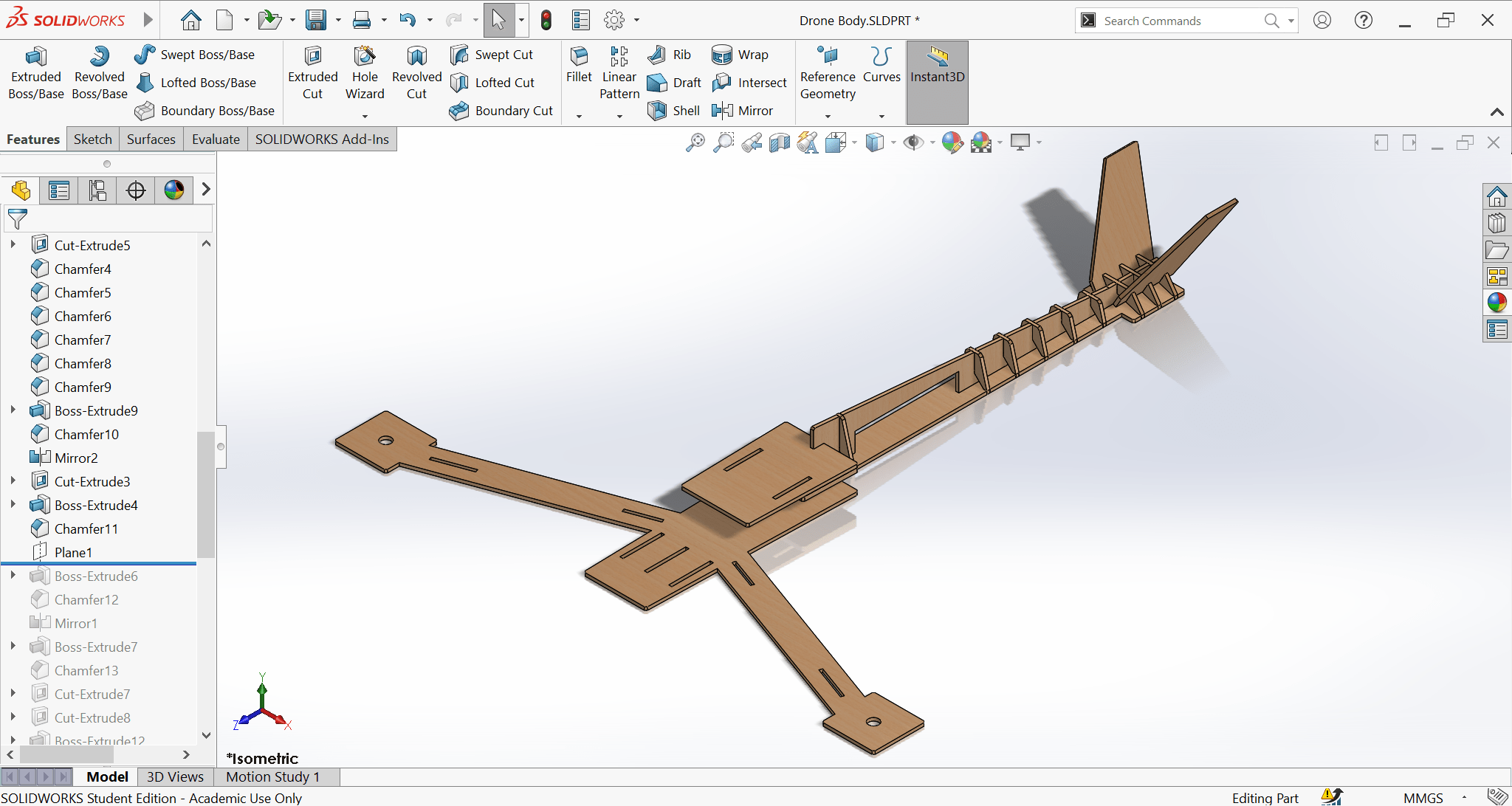
Then I added the vertical stabilizers, for the scope of this project, they are not functional, only aesthetics. Also, did some touch ups here and there to secure the tail ESC and the battery.
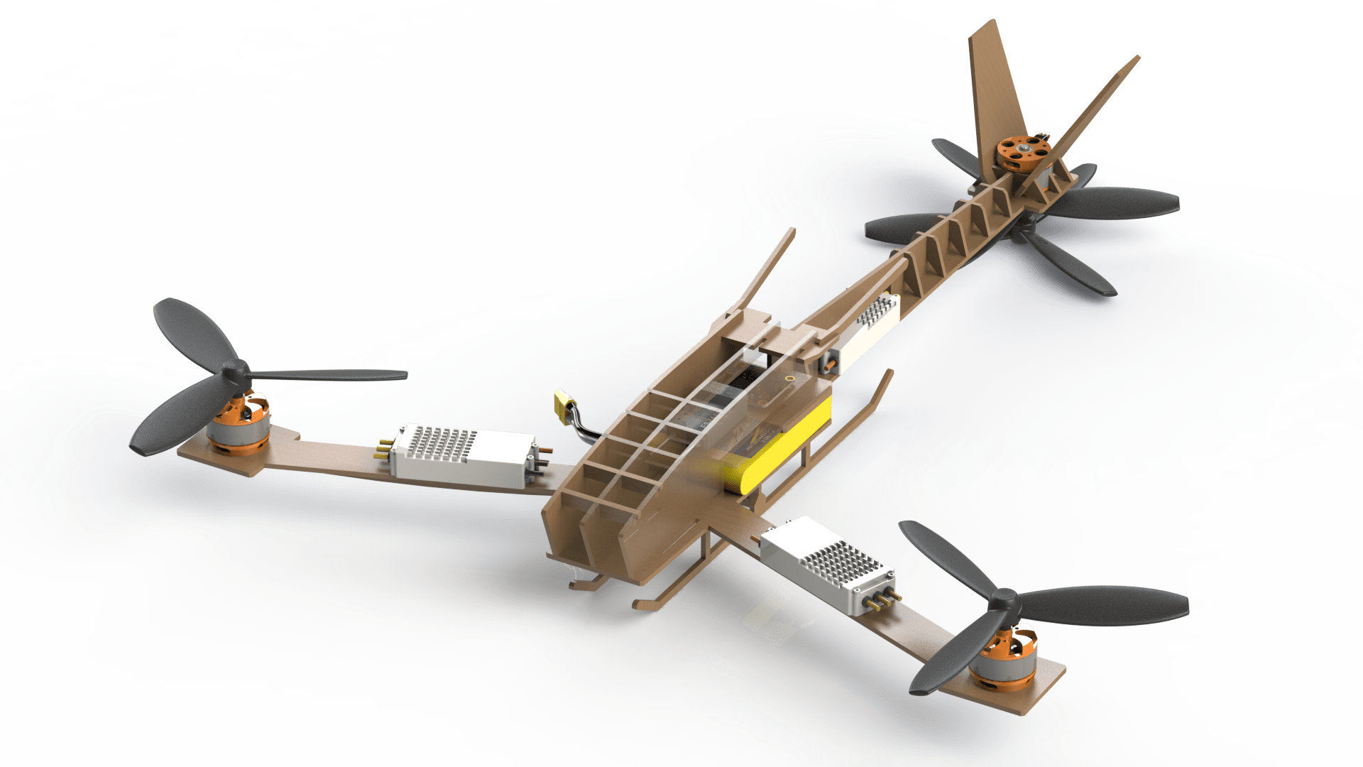
In this step, I added the fuselage, this is the place were all the electronics are housed.
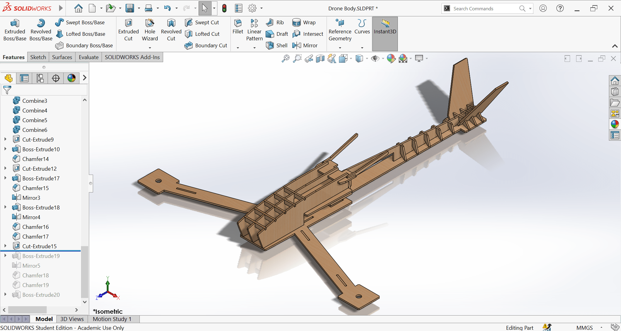
Finally, I added the landing gear.
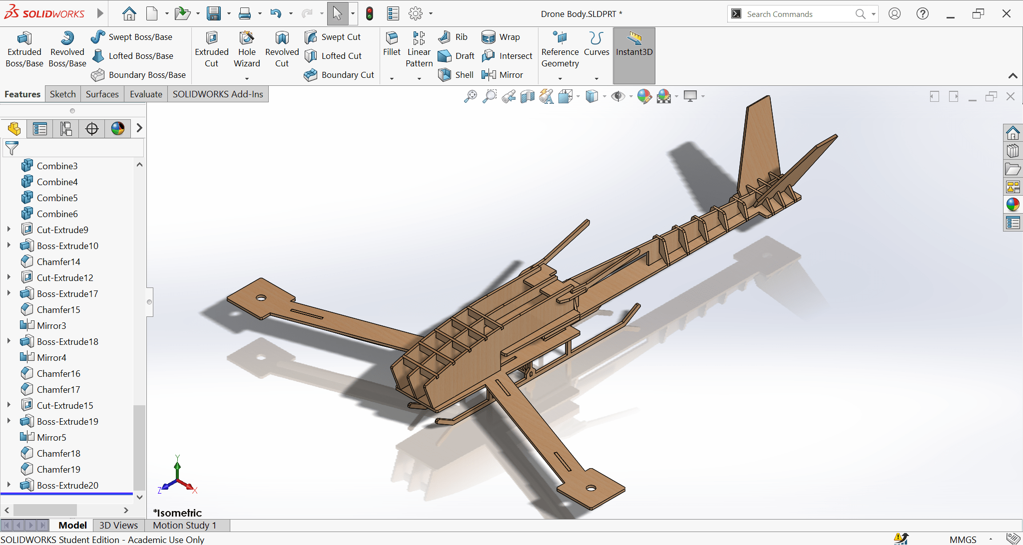
Here are some more rendered shots from different angles, enjoy!