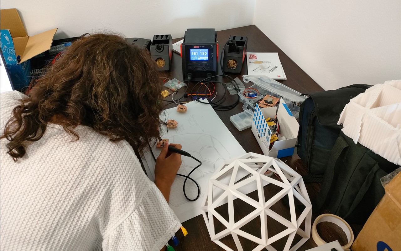
19. Project development
2D and 3D Modeling
To do the 3D modelling of the idea, I started using Catia software, as it is the programme I am most familiar with. The intention was to make a figure similar to the truncated icosahedron. However, once the prototype was made, and thinking about the usefulness of the product I wanted to make, I saw that it had too few faces, so I changed to a dome or geodesic dome of triangles. Nevertheless, I include the initial file in the following link: truncated icosahedron.
Studying the possibilities of this and other programs, I saw that in Blender there is an operation to create geodesic spheres almost automatically. So, I decided to design this product in Blender. To do this, just follow these steps: add -> mesh -> geodesic sphere (inside the layout). You have to choose the number of subdivisions (in this case 2) and the diameter of the original sphere (where the vertices of this dome would be).
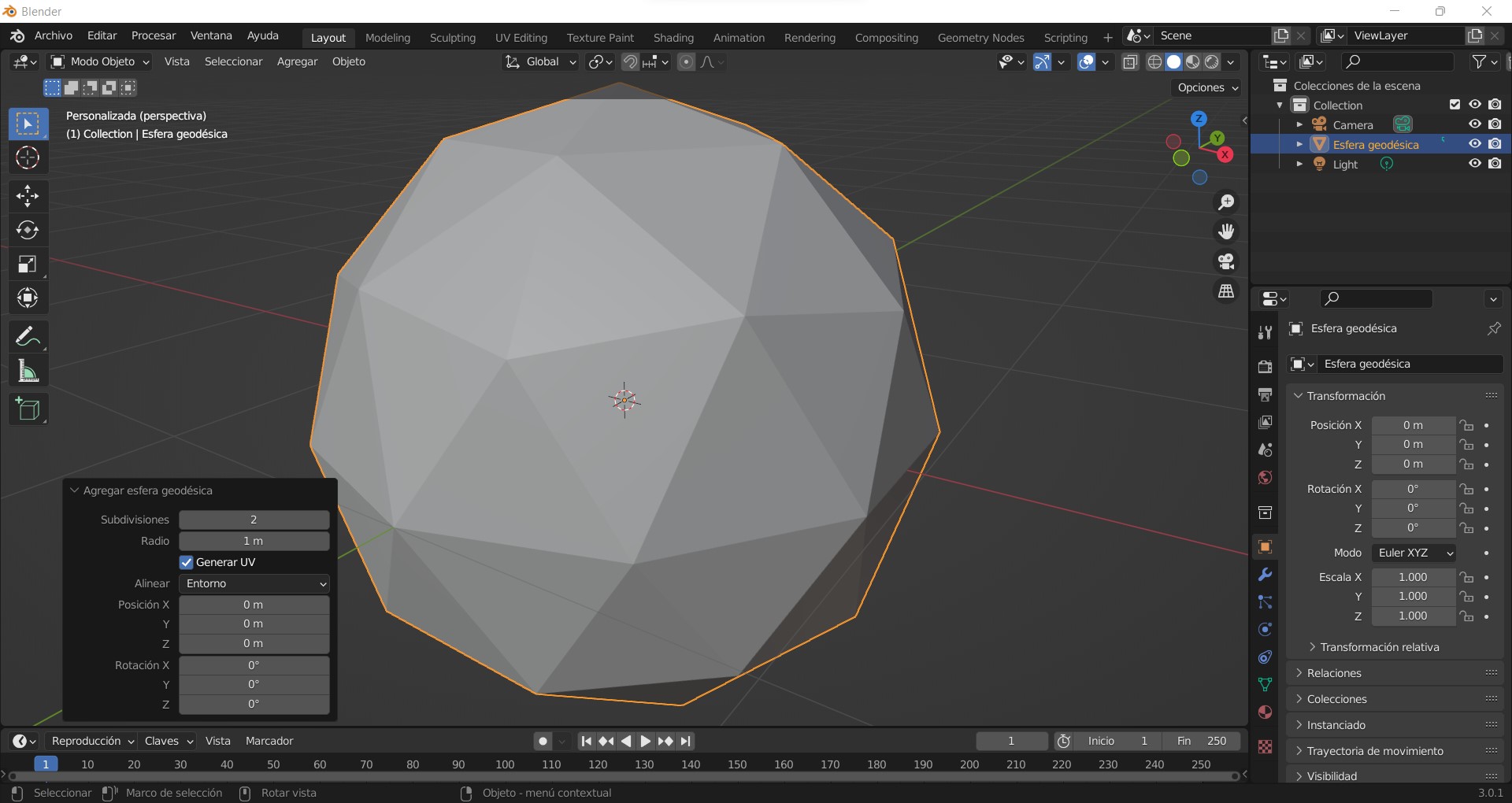
Once I had the geodesic sphere, I made a plane through the centre to divide it in 2 and keep a part of it. Then, I turned it into a structure by emptying its faces and defining a section with the desired thickness.
In the following video we can see the design of the dome.
Also, I tested the conduits thinking about the wiring that was necessary in our product. However, it complicated the manufacture of the object, so it was decided to eliminate those channels and keep the indicated structure.
The final model of the geodesic dome can be downloaded from the following links, both the original blender file and the stl file.
I have to comment that, in spite of having chosen blender because of the ease of designing a dome and all the advantages it offers, it has a disadvantage and that is that it does not take into account the units of measurement. This means that, even having done different tests and modifications in the radius of the original sphere, when exporting in stl for printing, the units are lost. In fact, there is no real relation if you increase the value, the piece is really bigger. I have not tested this for other file extensions.
Due to this reason and a better handling with other software, I went back to using Catia for the rest of the components of my product.
Thus, the whole base of the product, formed by 2 decagons (coinciding with the base of my geodesic dome) and two wooden boards, as well as the design of the triangles was made in Catia.
For the design of the decagons, some channels were made that would house the plates or walls of the base. These channels were made in 2 different ways. One of equal thickness to the thickness of the wood and with a depth of 1 mm, as it would be the one that would house the fixed wall of the base. The other would have a greater thickness, double, and a depth of 1.5 mm, so that the door could slide more easily.
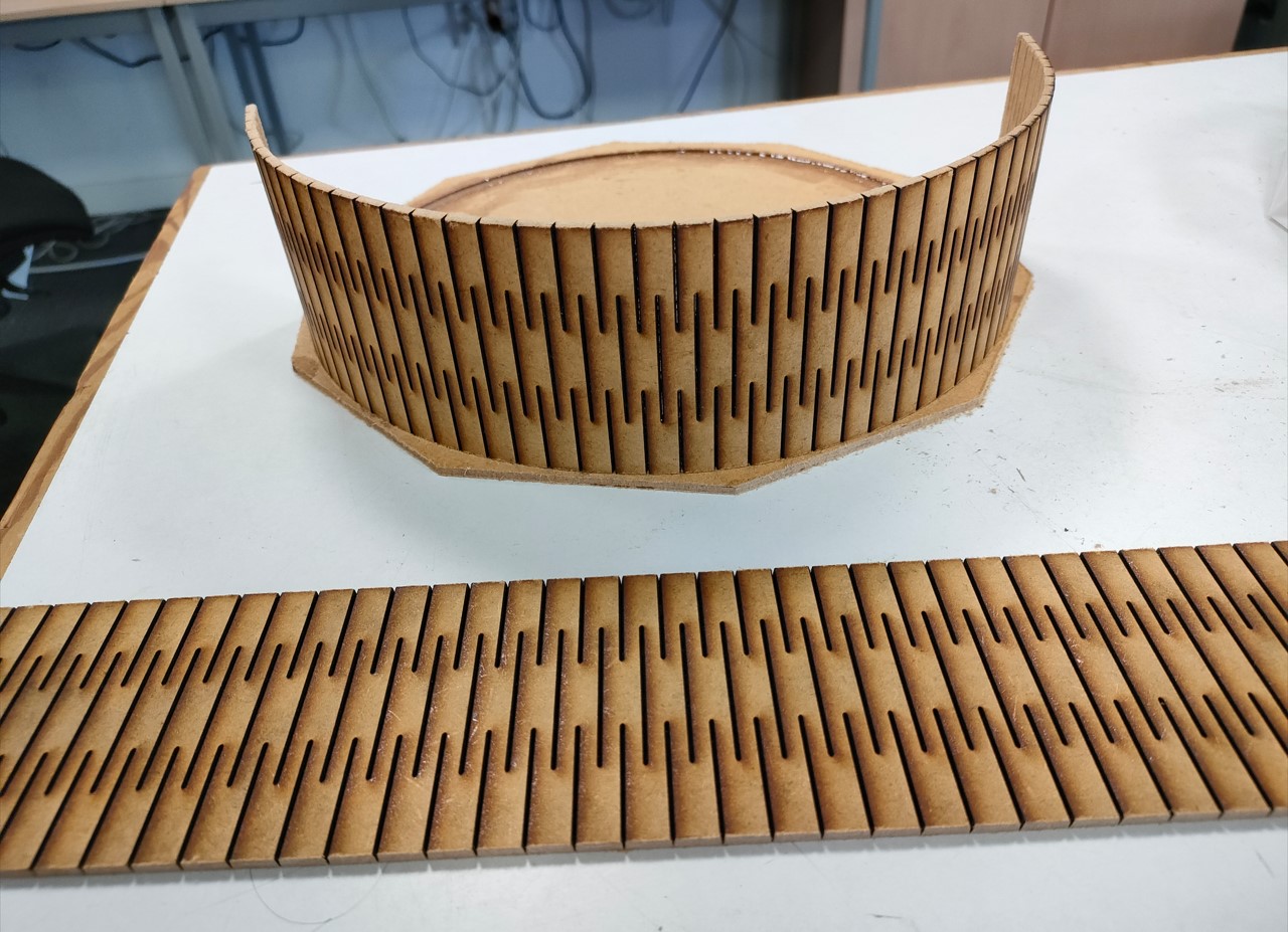
On the other hand, a pattern was designed to be able to bend the wood. Although this pattern was simulated and drawn in Catia, it was made in Autocad so that it was not necessary to fold the designed curved surface to a plane and to be able to cut it on the laser machine. The AutoCAD file can be downloaded from the following link.
3D printing
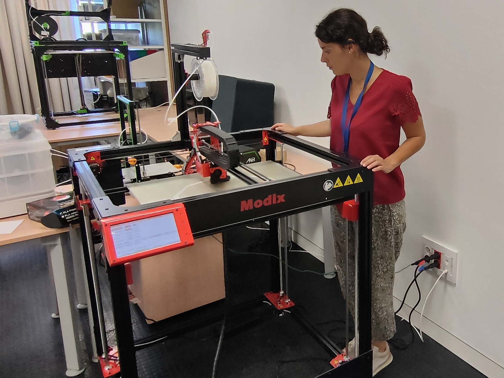
As I mentioned, the dome or main body was made in 3D printing with poly lactic acid (PLA). The machine used is the Modix BIG-60 V3.
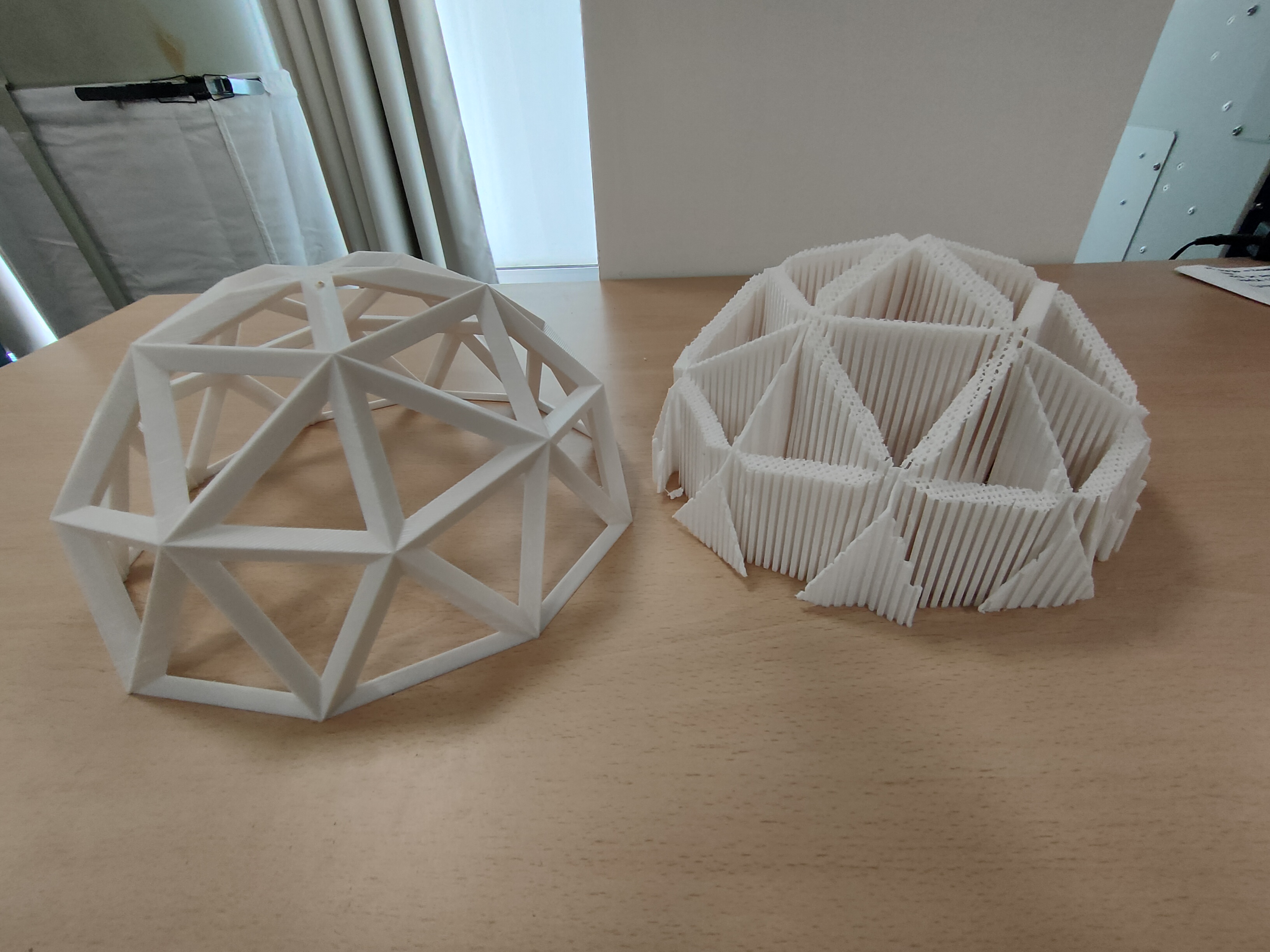
The manufacturing parameters were variable. This was due to the fact that 2 domes were made. A first dome in white, finer and more precise and with a better finish. Subsequently, I decided to make another one in black, to see which one looked more in keeping with the product. This second dome was made with a larger nozzle and layer thickness. The finish was a bit worse but the time was reduced from almost 4 days to 1 day and 5 hours. The following table shows the parameters used in both cases:
| Parameter | White dome | Black dome |
|---|---|---|
| Nozzle diameter | 0.4 mm | 1 mm |
| Layer thickness | 0.2 mm | 0.6 mm |
| Path width | 0.4 mm | 1 mm |
| Infill | 20% | 16% |
| Supports | 1 mm thickness / 30º | 0.6 mm thickness / 50º | Total time and material invested | 3 days 21 hours | 1 day 5 hours |
The figure shows the first dome designed and the number of supports required for its fabrication. The second structure was much more optimized, using less than half of the supports.
In addition, puzzle pieces and holes simulating the structure were also printed so that connection tests and initial welding could be carried out.
The files of these puzzle pieces and the holes can be downloaded from the respective links. It is important to know that they do not match the original dimensions as they were made before with the idea of seeing how I could connect the wires and make the contact of the LEDs contained in the puzzle pieces with the main structure.
Laser cutting
Laser cutting was used for the fixed wall and door that will form part of the base of the product. These two elements are very similar, only the fixed wall is slightly higher (1 mm above) so that the sliding door has more freedom of movement in the channels.
The material was a 3 mm thick wooden plank. As they were very large sheets (1200x800 mm) they had to be pre-cut on the CNC machine, as the maximum size of the laser machine is 500x500 mm.
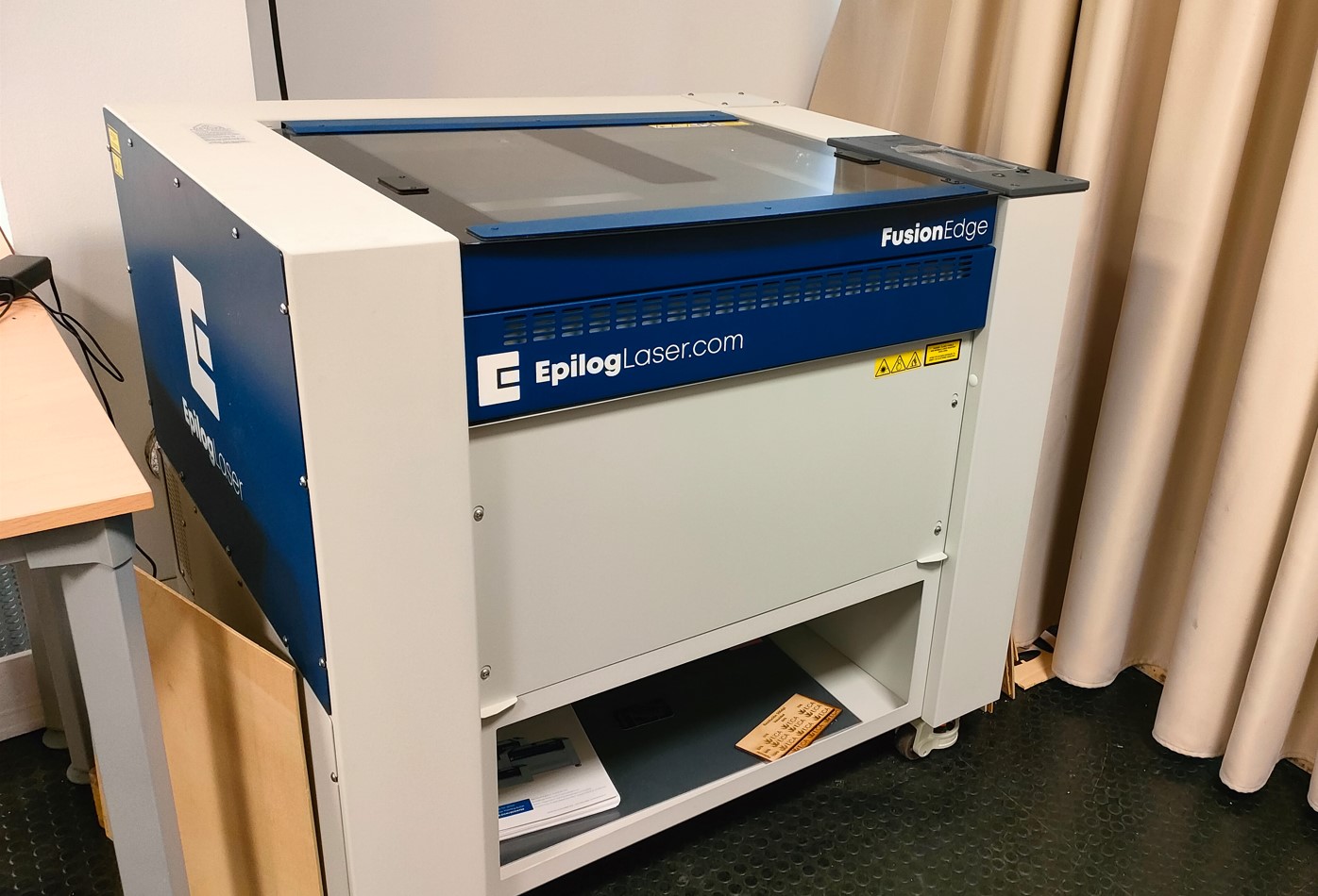
The machine used is the Epilog Fusion Edge.
For this purpose, files designed and saved in dxf or dwg format can be imported into the machine software. In this software, it is possible to apply different parameters for diferent lines. In this case, this is not necesary becouse I don´t want to make texturing or something similar.
The manufacturing parameters are listed below.
| Parameter | Value |
|---|---|
| Speed | 50% |
| Power | 40W |
| Pattern | Standar |
| Unidirectional | Off |
| Offset | 0 | Cycles | 2 |
CNC milling
The base of the product, as mentioned, is made of wood. It consists of two decagons (designed in the CAD section) with rails to include the fixed wall and the sliding door. These plates were milled on the Barcenas SW1325 CNC machine.
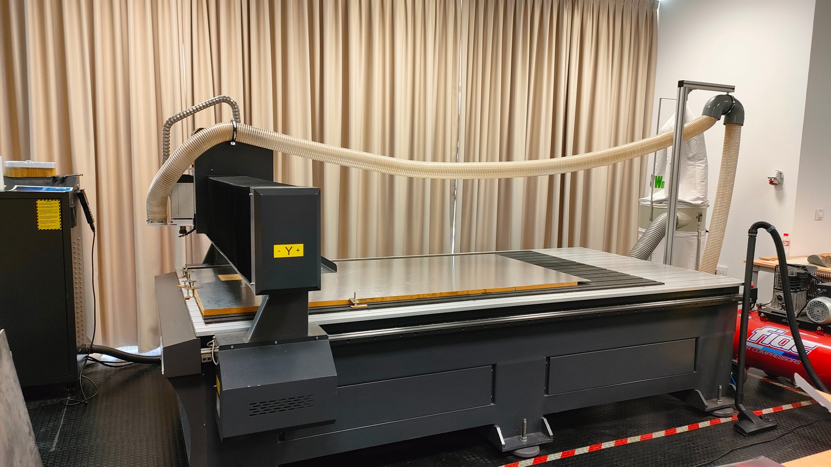
To cut the 3 mm thick wood, a 3 mm milling cutter, previously used in the week of the CNC machine, was also used.
The CAM program used for the creation of the machine code is Aspire. This program has a very simple interface.
First, the dimensions of the plate to be used are defined. In this case, a sheet of 800x1200 mm and 3 mm thick. We must also define our origin of coordinates or where the coordinates will go. In my case I chose the bottom left corner, as it is the one closest to the machine controls.
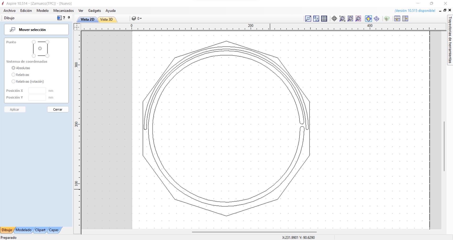
In the programme we can give each area of the drawing different parameters. The most important thing is that all contour lines are joined together. Even if we import a closed CAD file, this program sometimes detects that it is not closed. Actually, if we don't notice it, this is not a big problem but it slightly increases the machining times, because each line that is not joined means that the tool is not joined.
To avoid this problem, there is a specific button that joins the lines. Simply select them all and join them beforehand.
In this case, I have 3 completely distinguished zones:
- The decagon (or outer contour of the part to be cut). This needs to be milled, so it will be the last operation to avoid part movements.
- The rail for the fixed part or wall. It will have a depth of 1.5 mm and is almost as narrow as the thickness of the plate.
- The rail for the moving part or door. It has a depth equal to the previous one but it is wider so that the door does not get wedged when it is inserted in it.
The last two areas (the rails), since they have the same depth and are both >=3mm wide, can be machined using the same parameters and tooling. The parameters used for the complete cut are shown in the table below:
| Parameter | Rails | Decagon |
|---|---|---|
| Trajectory | Shaping | Profiling |
| Total cutting depth | 1.5 mm | 3.2 mm |
| Cutting inlet ramp | Yes | No |
| Number of passes | 1 | 2 |
| Spindle speed | 18000 rpm | 18000 rpm | Feed rate | 1200 mm/min | 1650 mm/min |
Once we have the two paths we have to pass them to machine language with the specific postprocessor of the SW1325 that is loaded in the same program.
With the file, we can now go to the machine. The first thing to do is to place our wood plank and fix it as best we can. This machine does not have a vacuum table, so long, thin boards tend to buckle in the center areas. There are several options to avoid this. The one used in this case is to place some double-sided tape in the areas furthest away from the tooling to ensure that the board is fixed to a sacrificial material placed underneath.
Then, we turn on the machine and it will automatically reference its axes. To make our 0, we must place ourselves in the desired X,Y position and hit the XY origin button. To make the 0 in Z this machine has a special function. Inside the control in advanced functions, we have the function "Probe". This consists of placing a probe that comes with the inductive machine, whose thickness is programmed, on the surface of our material. Thus, the head will go down little by little until the tool makes contact with the probe and the 0 in Z is saved automatically. You can also make the 0 manually, but I do not recommend it.
Then, we activate the extraction system (not active before because it makes a lot of noise).
We can now launch the program, always close to the emergency mushroom and with the personal protective equipment on.
Electronics design, cutting and soldering
The design of the plates went through several iterations. However, it was due to errors or things that had not been taken into account. Therefore, I will put the annotations on the correct plates here.
As I explained earlier, I chose to program my entire system with ATtiny 1614 microcontrollers, since they were the ones most readily available in the Lab.
These microcontrollers only have 9 analog pins, 2 of them are the ones used in the Rx and Tx protocol. In order to leave the sending communication available, we left the Tx unused and because as I proposed the code I need pairs of pins (having a single one and combining it with another board would complicate the programming a lot).
Thus, I will allocate 4 pairs of analog pins for 4 holes in the structure. Therefore I need 10 slave boards (there are 40 holes) that will be governed by a master board.
However, all these slave boards will be exactly the same, and only the identification (adress) will change in the programming of each one.
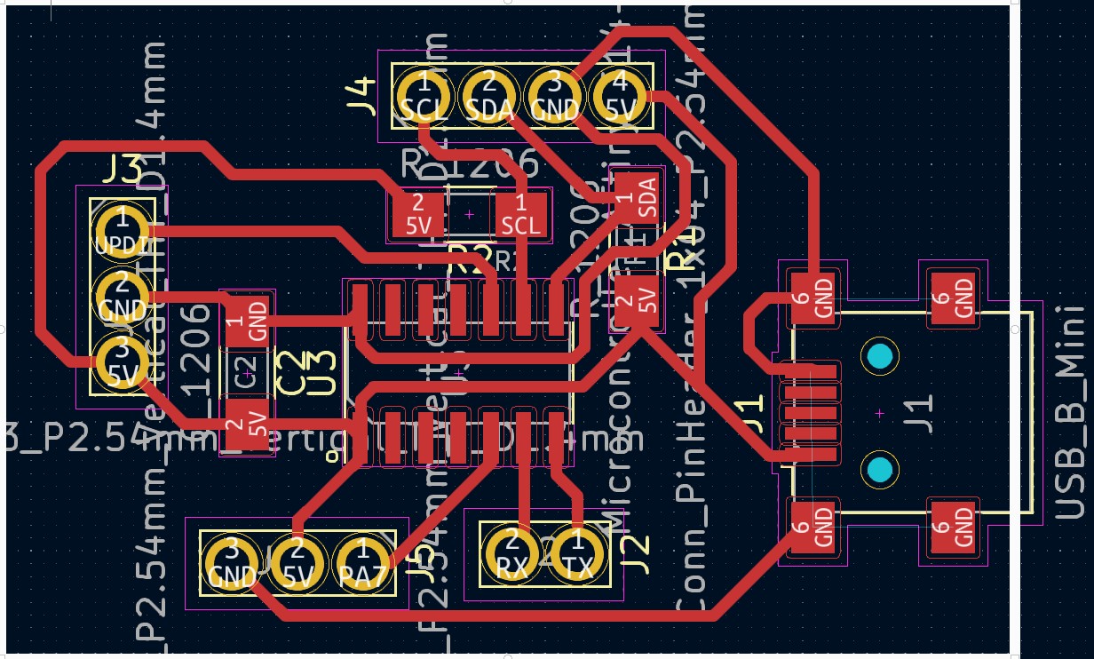
Thinking about what a board should include to control leds and at the same time be communicating with a master board, I obtained the following board structure:
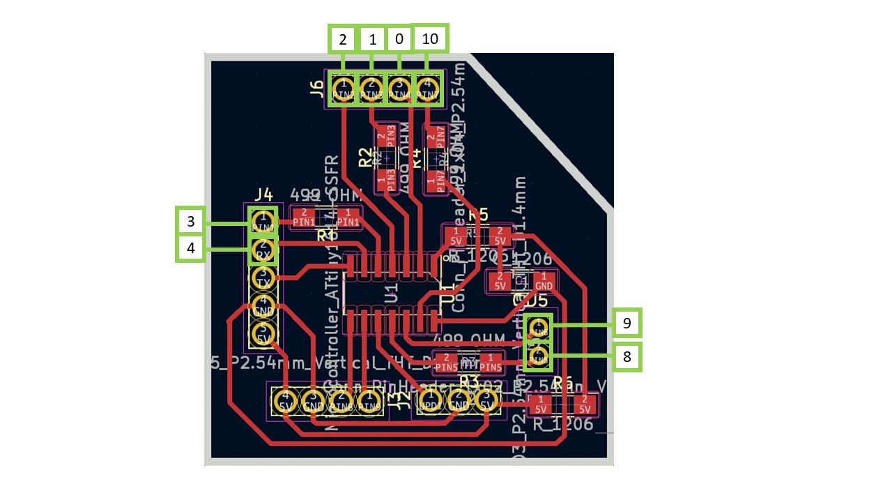
On the left are the pins on each slave board (they will be similar on all slave boards); on the right are the pairs of pins that would form each triangle, numbered 0 to 3 on the first board (4 to 7 on the 2nd board, 8 to 11 on the 3rd and so on up to 39).
With the proposed structure, as can be seen in the figure, a resistor is required for each pair of pins (499 ohm but can be less, it is not to melt the LED); a pair of 0 ohm resistors that are only placed to bridge and not to cross the traces, a capacitor, the microcontroller mentioned and the output pins.
The output pins have been arranged in such a way that it was easy to locate various things:
- The SDA and SCL pins, which together with GND and 5V form the 4 output pins on the lower left side of the board. These pins will be used to connect all the boards to the master with wiring.
- The UPDI, which also together with GND and 5V is at the bottom right of the board, to have the programming accessible.
- The Tx and Rx pins, also with GND and 5V to validate that the board works before final assemblies. The Rx will also serve later as a pin for one of the holes in the structure.
- The pins are independent so that each pair is equivalent to the position of a triangle.
On the other hand I will have my master board, with a simpler structure:
Where the pins are also taken out of all the communication protocols mentioned in the previous one (SDA-SCL; Rx-Tx; UPDI) and a single free pin in case at some point I would like to add a sound or vibration output for example when winning the game or when putting a piece (not finally used).
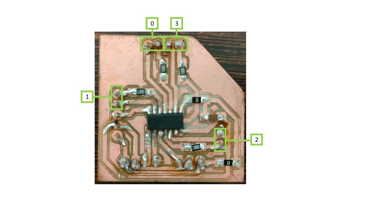
After designing the plates in KiCad, they were cut on the SMR-20 milling machine, with the same tools and parameters as those used in the electronics production week. Then, they were soldered and checked with the multimeter if there was continuity and no short circuit.
In this aspect I had some problems with the soldering. After many tests I observed that it was the tin used in the soldering and not using solder paste or flux liquid.
Programming
To program this work I proposed different options. The chosen option is one that offered me less wires, and given the complex geometry to develop was the one chosen for this work.
In general, each hole of the triangle is controlled by a pair of pins. This will work so that if I put one pin HIGH and the other LOW or vice versa I can see if there is a triangle of the first device or the second (since the LEDs are placed with the poles reversed). If there is no current in either case, there is no triangle connected. The idea is that I am going to have several boards to control all the holes (specifically 10 boards, each of them controlling 4 holes). Each board will turn on the triangle (whatever the color or player that places it) and will send the information to the Master board as a vector of 40 positions (each one corresponds to a hole). Each position will be a 1 if it belongs to team 1 (blue), a 2 if it belongs to team 2 (white) or a 0 if there is no triangle placed.
This data structure simplifies the code for me (since making a variable "board" would be more complex) but complicates the assembly and wiring of the structure. Since I have to have very clear and schematized which wire goes with which pin (without being able to be interchanged).
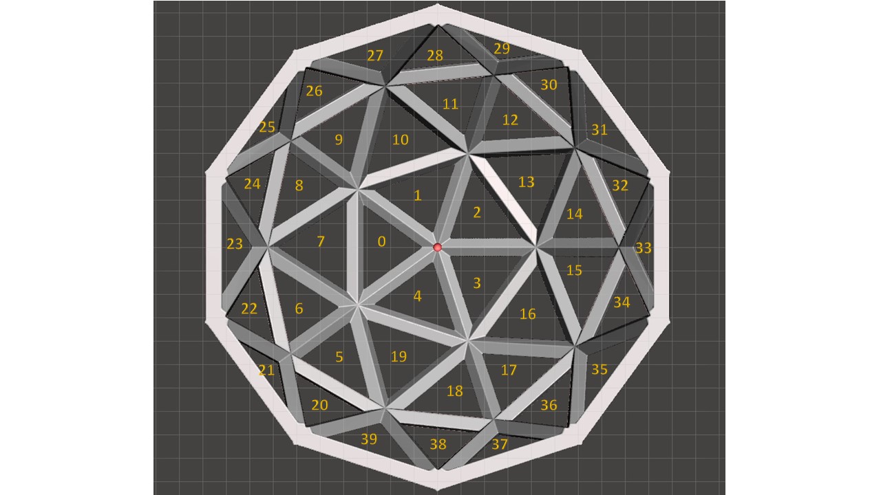
In addition, which board controls which triangles is very important. For ease of work the plates are in order, so that the 1st controls the triangles: 0, 1, 2 and 3, the 2nd controls: 4, 5, 6 and 7, and so on.
On the other hand, the Master board, by collecting all the positions and knowing which triangles are in each position, checks which neighboring triangles are in each of the holes. Thus, when a triangle is placed, the master checks its 3 neighbors. If any of them is on, it checks its 3 neighbors, and repeats this operation a third time to obtain the "4 in line". For the triangles to be neighbors it is necessary to have a side in common.
Also, in order not to make a dissimilar matrix of the neighbors, I have put a non-existent pin (number 100). This is because there are 10 holes of the structure (those whose lower or horizontal sides form the base of the structure or the base decagon) that have only 2 neighbors. This does not affect the code since the triangle 100 will always be equal to 0.
The code of the Master plate is given below (some notes are in my native language). It can also be downloaded for arduino from the following link.
        #include
          int triangulos[] = {
            0, 0, 0, 0,
            0, 0, 0, 0,
            0, 0, 0, 0,
            0, 0, 0, 0,
            0, 0, 0, 0,
            0, 0, 0, 0,
            0, 0, 0, 0,
            0, 0, 0, 0,
            0, 0, 0, 0,
            0, 0, 0, 0
          };

          int index;
          int contador_azules = 0;
          int contador_blancos = 0;
          int azules[4] = { 50, 50, 50, 50 };
          int blancos[4] = { 50, 50, 50, 50 };

          int vecinos[40][3] = {
            { 1, 4, 7 },   // vecinos de 0
            { 0, 2, 10 },  // ...
            { 1, 3, 13 },
            { 2, 4, 16 },
            { 1, 3, 19 },
            { 6, 19, 20 },
            { 5, 7, 22 },
            { 0, 6, 8 },
            { 7, 9, 24 },
            { 8, 10, 26 },
            { 1, 9, 11 },  // vecinos 10
            { 10, 12, 28 },
            { 11, 13, 30 },
            { 2, 12, 14 },
            { 13, 15, 32 },
            { 14, 16, 34 },
            { 3, 15, 17 },
            { 16, 18, 36 },
            { 17, 19, 38 },
            { 4, 5, 18 },  // vecinos de 19
            { 5, 21, 39 },
            { 20, 22, 100 },  // 100 no existe
            { 6, 21, 23 },
            { 22, 24, 100 },
            { 8, 23, 25 },
            { 24, 26, 100 },
            { 9, 25, 27 },
            { 26, 28, 100 },
            { 11, 27, 29 },
            { 28, 30, 100 },
            { 12, 29, 31 },
            { 30, 32, 100 },
            { 14, 31, 33 },
            { 32, 34, 100 },
            { 15, 33, 35 },
            { 34, 36, 100 },
            { 17, 35, 37 },
            { 36, 38, 100 },
            { 18, 37, 39 },
            { 20, 38, 100 }
          };


          void setup() {
            Wire.begin();        // join i2c bus (address optional for master)
            Serial.begin(9600);  // start serial for output
          }

          void loop() {
            leerTriangulo(1, 0);
            leerTriangulo(2, 4);
            leerTriangulo(3, 8);
            leerTriangulo(4, 12);
            leerTriangulo(5, 16);
            leerTriangulo(6, 20);
            leerTriangulo(7, 24);
            leerTriangulo(8, 28);
            leerTriangulo(9, 32);
            leerTriangulo(10, 36);

            for (int i = 0; i < 40; i++) {
              Serial.print(triangulos[i]);
              Serial.print(" , ");
            }
            Serial.println("");
            comprobar_azules();
            comprobar_blancos();
            delay(1000);
          }


          void leerTriangulo(int adress, int indiceInicial) {
            Wire.requestFrom(adress, 4);  // request 4 bytes from slave device #1
            index = indiceInicial;
            Serial.println(adress);
            while (Wire.available()) {  // slave may send less than requested
              int c = Wire.read();      // receive a byte as character
              Serial.println(c);
              triangulos[index] = c;
              index = index + 1;
            }
          }

          void comprobar_azules() {
            //comprobar fichas azules
            for (int i = 0; i < 40; i++) {
              if (triangulos[i] == 1 && (contador_azules < 4)) {  //1 azul, 2 blanco, 0 nada
                azules[contador_azules] = i;
                contador_azules++;                                                // contamos 1º azul
                for (int j = 0; j < 3; j++) {                                     // buscamos el 2º azul
                  if (triangulos[vecinos[i][j]] == 1 && (contador_azules < 4)) {  // buscar en los vecinos el valor
                    azules[contador_azules] = vecinos[i][j];
                    contador_azules++;  // contamos 2º azul
                    for (int k = 0; k < 3; k++) {
                      if ((triangulos[vecinos[vecinos[i][j]][k]] == 1) && (in_array(azules, vecinos[vecinos[i][j]][k])) && (contador_azules < 4)) {  // buscar en los vecinos el valor
                        azules[contador_azules] = vecinos[vecinos[i][j]][k];
                        contador_azules++;  // contamos 3º azul
                        for (int l = 0; l < 3; l++) {
                          if ((triangulos[vecinos[vecinos[vecinos[i][j]][k]][l]] == 1) && (in_array(azules, vecinos[vecinos[vecinos[i][j]][k]][l])) && (contador_azules < 4)) {  // buscar en los vecinos el valor
                            azules[contador_azules] = vecinos[vecinos[vecinos[i][j]][k]][l];
                            contador_azules++;  // contamos 4º azul
                          }
                        }
                      }
                    }
                  }
                }
              }
              if (contador_azules == 4) {
                Serial.print("Azul gana");
                for (int y = 0; y < 4; y++) {
                  Serial.print(azules[y]);
                  Serial.print(" ");
                }
                Serial.println("");
              } else {
                contador_azules = 0;
                for (int t = 0; t < 4; t++) {
                  azules[t] = 50;
                }
              }
            }
          }

          void comprobar_blancos() {
            //comprobar fichas blancos
            for (int i = 0; i < 40; i++) {
              if (triangulos[i] == 1 && (contador_blancos < 4)) {  //1 blanco, 2 blanco, 0 nada
                blancos[contador_blancos] = i;
                contador_blancos++;                                                // contamos 1º blanco
                for (int j = 0; j < 3; j++) {                                     // buscamos el 2º blanco
                  if (triangulos[vecinos[i][j]] == 1 && (contador_blancos < 4)) {  // buscar en los vecinos el valor
                    blancos[contador_blancos] = vecinos[i][j];
                    contador_blancos++;  // contamos 2º blanco
                    for (int k = 0; k < 3; k++) {
                      if ((triangulos[vecinos[vecinos[i][j]][k]] == 1) && (in_array(blancos, vecinos[vecinos[i][j]][k])) && (contador_blancos < 4)) {  // buscar en los vecinos el valor
                        blancos[contador_blancos] = vecinos[vecinos[i][j]][k];
                        contador_blancos++;  // contamos 3º blanco
                        for (int l = 0; l < 3; l++) {
                          if ((triangulos[vecinos[vecinos[vecinos[i][j]][k]][l]] == 1) && (in_array(blancos, vecinos[vecinos[vecinos[i][j]][k]][l])) && (contador_blancos < 4)) {  // buscar en los vecinos el valor
                            blancos[contador_blancos] = vecinos[vecinos[vecinos[i][j]][k]][l];
                            contador_blancos++;  // contamos 4º blanco
                          }
                        }
                      }
                    }
                  }
                }
              }
              if (contador_blancos == 4) {
                Serial.print("Blanco gana");
                for (int y = 0; y < 4; y++) {
                  Serial.print(blancos[y]);
                  Serial.print(" ");
                }
                Serial.println("");
              } else {
                contador_blancos = 0;
                for (int t = 0; t < 4; t++) {
                  blancos[t] = 50;
                }
              }
            }
          }


          bool in_array(int array[], int value) {
            for (int m = 0; m < 4; m++) {
              if (array[m] == value) {
                return true;
                break;
              }
            }
            return false;
          }
The code for the slave boards is given below (some annotations are in my native language). Just note that each board has its own adress (they have been named from 1 to 10). It can also be downloaded for arduino from the following link.
        #include

          int triangulos[] = {0, 0, 0, 0};
          int pin1Triangulos[] = {1, 3, 8, 10};
          int pin2Triangulos[] = {2, 4, 9, 0};

          unsigned long previousMillis = 0;  // will store last time LED was updated
          const long interval = 500;  // interval at which to blink (milliseconds)


          void setup() {
            Wire.begin(3); //This code is for the board 3
            Wire.onRequest(requestEvent);

              // put your setup code here, to run once:
            Serial.begin(9600);
          }

          bool check(int pin1, int pin2) {
            pinMode(pin1, INPUT_PULLUP);
            pinMode(pin2, OUTPUT);
            digitalWrite(pin2, LOW);
            if (digitalRead(pin1) == 0) {
              return true;
            }
            else {
              return false;
            }
          }

          void ledOn(int pin1, int pin2) {
            pinMode(pin1, OUTPUT);
            pinMode(pin2, OUTPUT);
            digitalWrite(pin1, HIGH);
            digitalWrite(pin2, LOW);
          }


          void loop() {
            for (int i = 0; i < 4; i++) {
              if (triangulos[i] == 0) {
                if (check(pin1Triangulos[i], pin2Triangulos[i])) {
                  triangulos[i] = 1;
                  Serial.print("Connected pos  ");
                  Serial.println(1);
                  ledOn(pin1Triangulos[i], pin2Triangulos[i]);
                }
                else if (check(pin2Triangulos[i], pin1Triangulos[i])) {
                  triangulos[i] = 2;
                  Serial.print("Connected pos  ");
                  Serial.println(2);
                  ledOn(pin2Triangulos[i], pin1Triangulos[i]);
                }
              }

              else {
                unsigned long currentMillis = millis();
                if (currentMillis - previousMillis >= interval) {
                  // save the last time you blinked the LED
                  previousMillis = currentMillis;

                  if (triangulos[i] == 1) {
                    Serial.print("triangulo  ");
                    Serial.println(i);
                    Serial.println("Cheking 1");
                    if (!check(pin1Triangulos[i], pin2Triangulos[i])) {
                      triangulos[i] = 0;
                    }
                    else {
                      ledOn(pin1Triangulos[i], pin2Triangulos[i]);
                    }
                  }
                  else if (triangulos[i] == 2) {
                    Serial.println("Cheking 2");
                    if (!check(pin2Triangulos[i], pin1Triangulos[i])) {
                      triangulos[i] = 0;
                    }
                    else {
                      ledOn(pin2Triangulos[i], pin1Triangulos[i]);
                    }
                  }
                }
              }
            }
          }

          void requestEvent() {
           for (int i = 0; i < 4; i++) {
           Wire.write(triangulos[i]);
          }
          }
Making puzzle parts
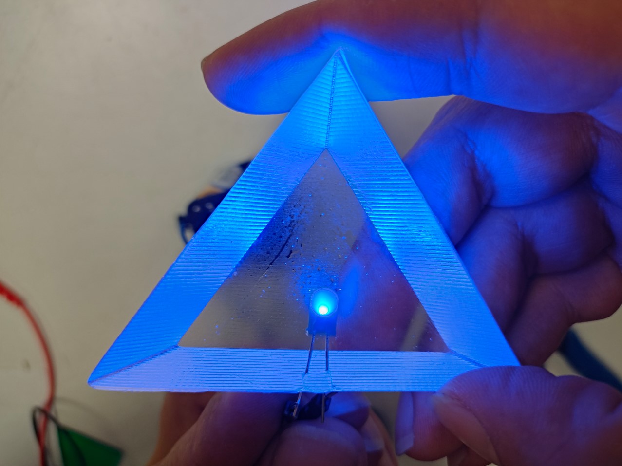
The puzzle pieces had to be transparent and have embedded electronics. First I thought about having the resistor inside the piece itself, and RGBs instead of LEDs but that system would complicate the cabling. So, I decided that there were going to be two types of pieces, each one of a different color. Each color would have the LED placed in a different position. So, all the blue chips will have the positive LED pole to the left and the white chips will have the positive LED pole to the right.
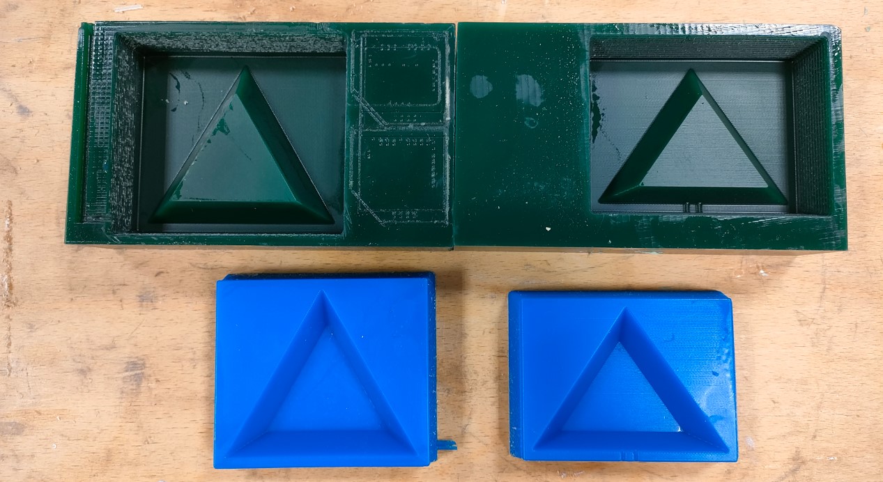
However, the first thing was to obtain the molds, since the only way to obtain transparent parts with embedded LEDs was by epoxy casting.
Thus, after having done 3D printing tests, they were obtained, and from the design of the puzzle pieces or triangle models, the wax models were designed.
The wax models were designed in such a way that they had a 10% demolding angle and a volume above with a depth of 10 mm.
Once designed, the models were machined in wax blocks, as was done during the molding and casting week. The same parameters and tools were used as in the molding and casting week, since very good results were obtained.
In a first iteration, the first model did not include an LED positioning zone. For the second mould that was made, two channels were included to position it. However, when the silicone mould was later obtained, these channels were manually made for the one that did not have them. This way the LED will always be equally centred on the part and the parts will be interchangeable (so that any part can make contact in any hole of the structure).
Silicone moulds were then obtained. In this case, the silicone used during the moulding and casting week was out of stock. So, I chose another silicone (in this case blue) from Reschimica.
This silicone does not have any outstanding features. It has a working time of 40 minutes and a setting time of 3 hours. The ratio of its components is 1:1 so you only have to calculate the desired volume to be filled and divide it by 2 to pour each quantity of each of the components.
Once the silicone moulds were obtained, the resin parts were taken out. First, the silicone mould was cleaned well with a little isopropyl alcohol. Then, we applied a spray mould release agent. Place the LED in the desired position, taking care whether it is blue or white. To obtain the same number of blue and white LEDs, we made one of each colour in each batch.
The epoxy used again was that of the moulding and casting week. This time, more caution and patience was used to remove as many bubbles as possible. Also, the curing process was accelerated by slightly heating the samples.
Finally, two additional silicone moulds were produced. In this way, the 40 triangles could be obtained in less time (mass production).
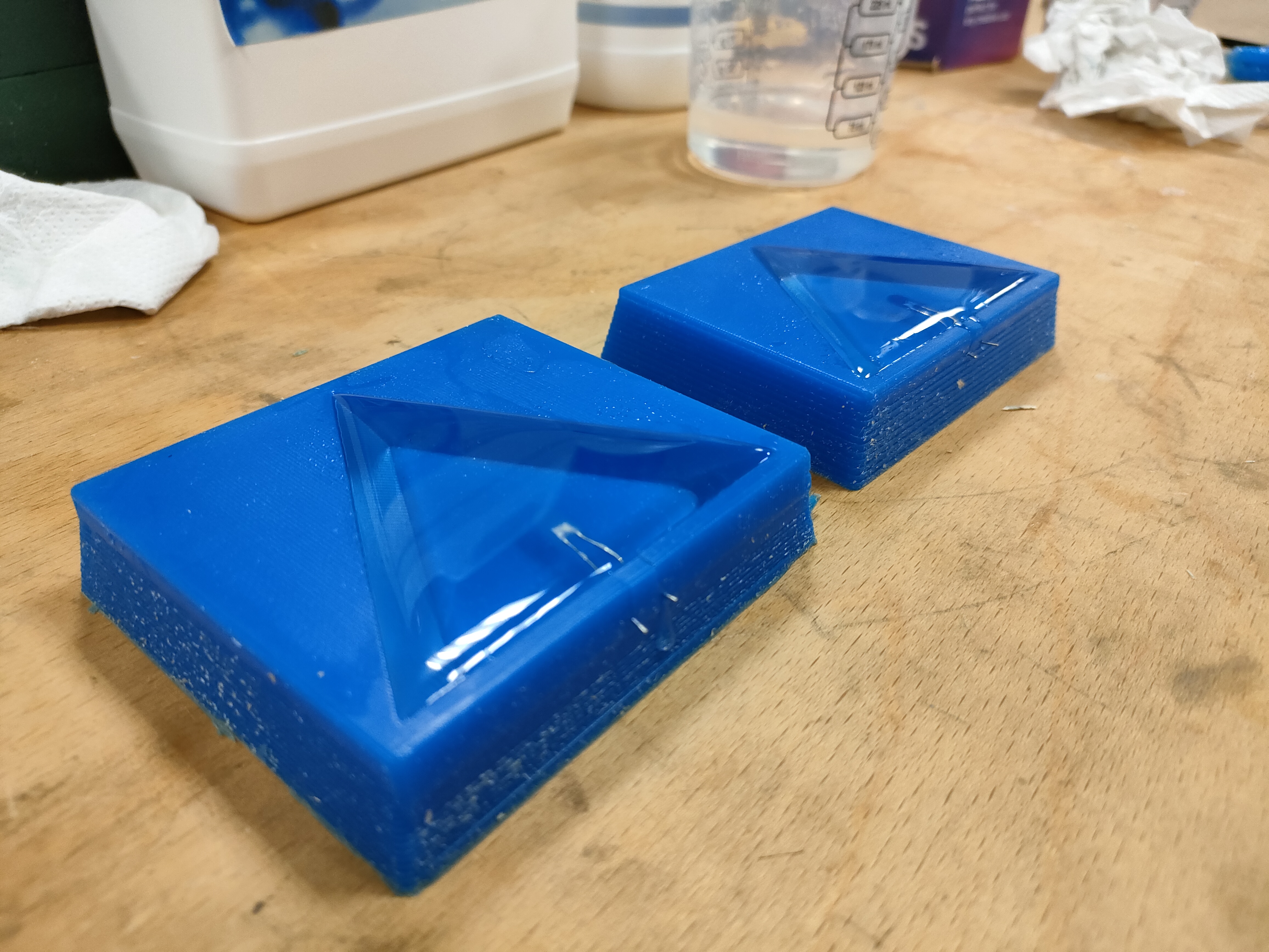
After use and forced heating to accelerate the process, a marked degradation of the moulds was observed (despite not having removed as many parts from each mould).
Despite this, the parts came out as desired (no vacuum for bubble removal) and an example of a blue part looked as shown in the picture.
Assembly
And then we come to the assembly part. At this point most might think that the easiest part is left...wrong.
The way I have planned the programming, as I have a "fixed" board structure, I must connect the wires exactly in the board that corresponds. So, I had to make a wiring diagram and triangles, as shown in the figure.
Thus, the copper tape started by gluing the copper tape in the correct positions in each hole of the structure. The triangle will only make contact in one position (the larger side of the triangle, as this is where the integrated LED is).
Then, two cables were labelled for each hole and glued with black silicone through the channels included in the structure.
Once they had been glued together, the ends were picked up and welded. Once soldered and glued, we thought about where the wires would be routed to the lower part of the base. Holes were drilled in each corner or vertex of the wooden base, with a distance where the walls and door of the base will be assembled later.
On the other hand, the base was welded by inserting the wall or fixed plate into the narrow channel of one of the decagons and some transparent silicone was applied to fix it (from the inside).
For the sliding door, even with a wider track, there was no good sliding. So, the channel was lightly coated with a layer of epoxy, to make it slide more smoothly.
The upper decagon was not glued to the fixed wall, although it was glued to the plastic structure. This was done in this way to make it easier to dismantle if necessary.
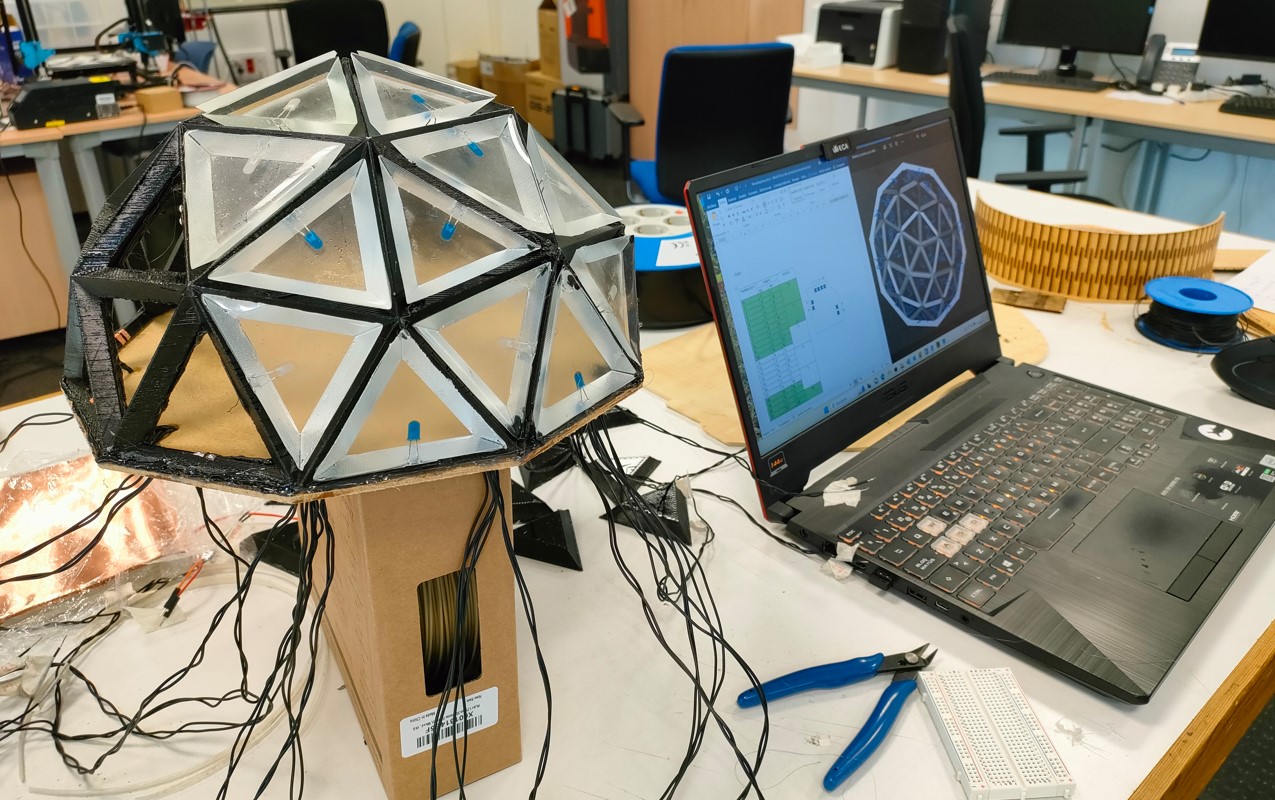
Testing
In reality the testing was done prior to final assembly. This was because, as I mentioned earlier, we only had 4 fully fabricated, soldered and programmed slave boards. So, they were first used to test the whole structure and finally used in a single area.
The tests worked satisfactorily. Some welding had to be reworked and manufacturing tolerances could be improved (especially in the structure).
Final prototype and files
And this is how the final prototype turned out:

The video, poster and files of the product parts are collected on the final project page.