13. Molding & Casting
This week we learned how to design suitable objects within the constraints of 3-axis machining and tooling. We also learned about the workflow used in designing, building and casting molds.
The steps to follow are:
- 1. Create a positive mold model. Design for manufacturing
- 2. Mill the wax. Machining
- 3. Make a mold from the wax. Mold creation / Silicone casting
- 4. Cast Final Object. Final model
Design for manufacturing
In the design phase, it was decided to make 2 molds: mold 1 with one side, and mold 2 with two sides.
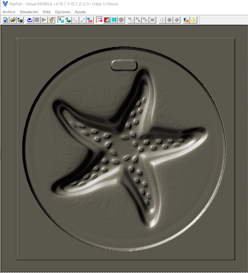
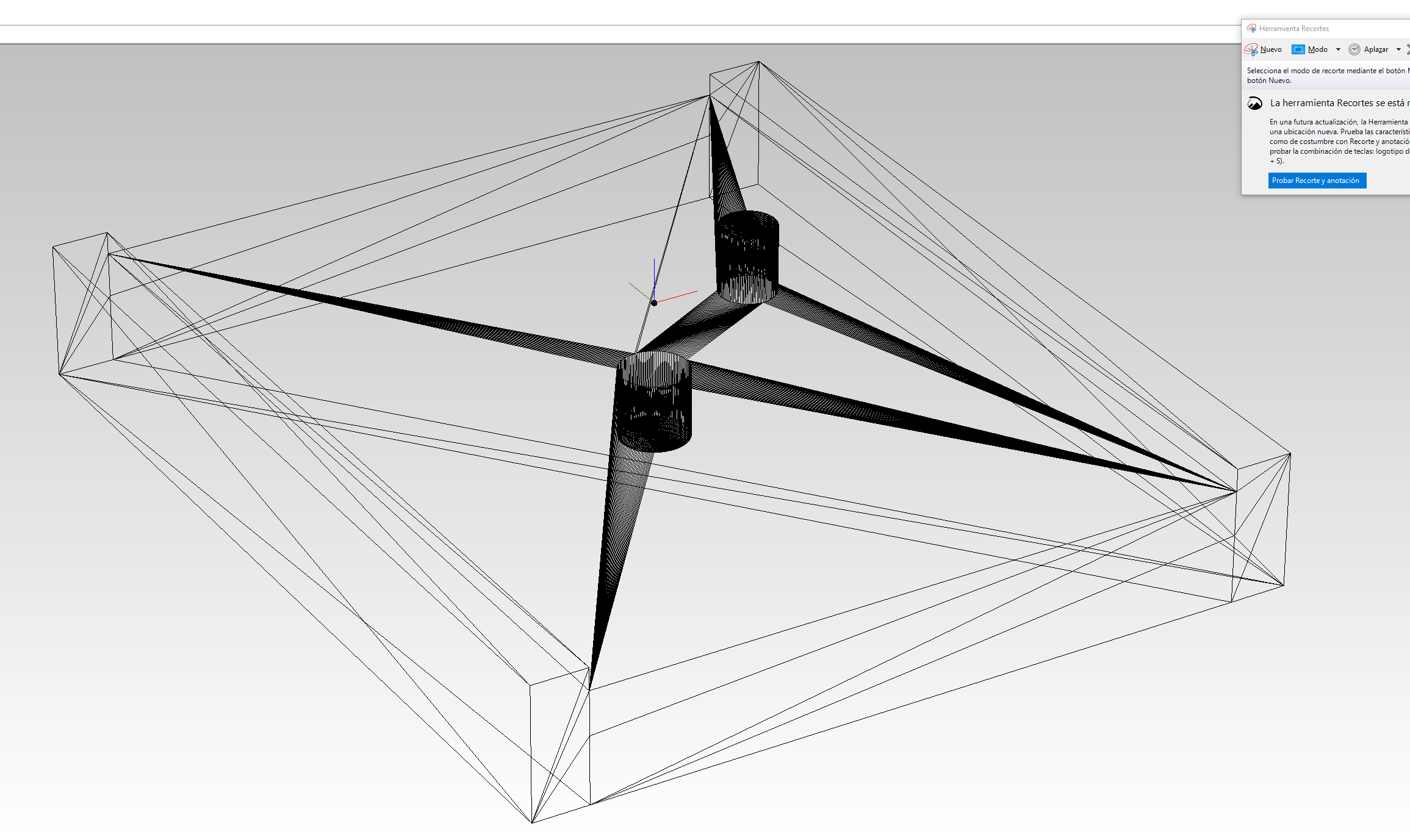
For mold 1 it was decided to choose a ready-made model, to see and understand the design constraints. The model chosen is shown in the image.
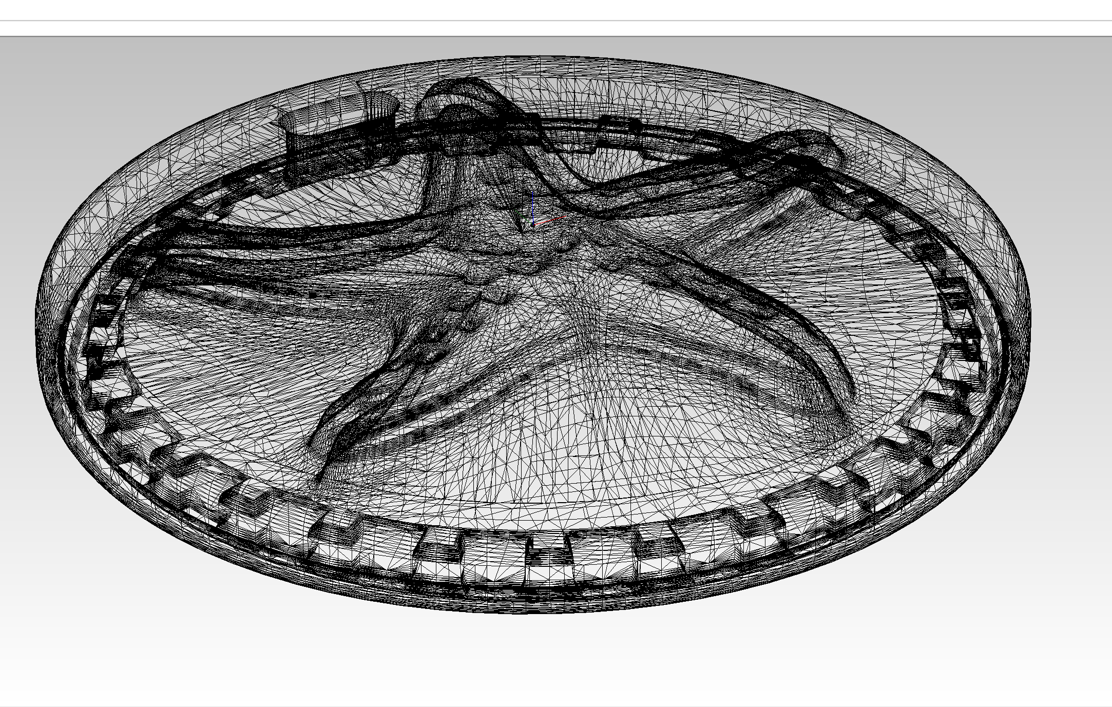
This mold only has extrusion in the Z-axis (and not very steep) so the tool looks like it could reach all zones. The design does not contemplate the mold walls, only the model to be obtained. This has been done intentionally to see how the CAM software works under this situation.
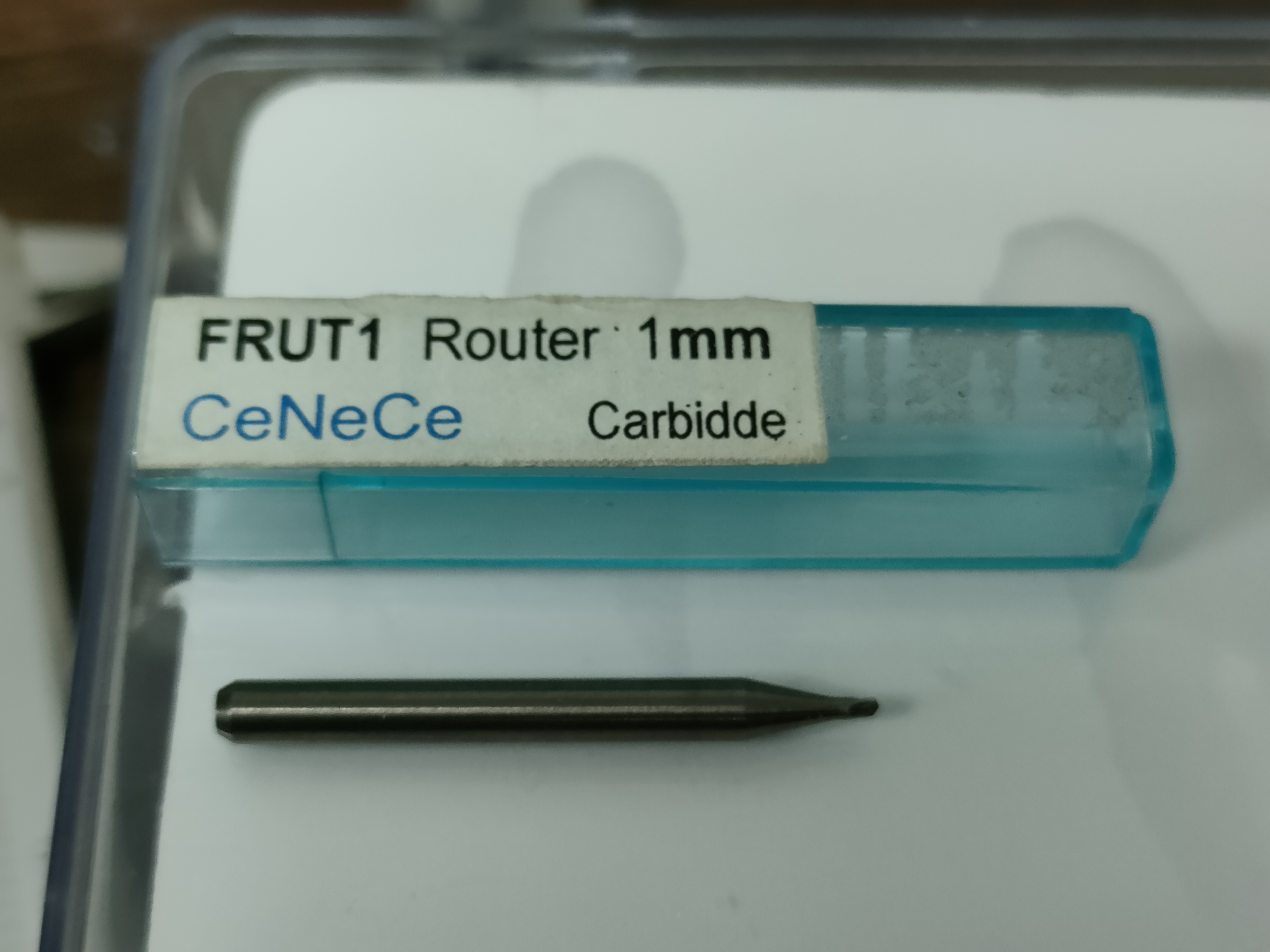
The tools proposed for the creation of the mold are listed below with their respective parameters:
| Tool | 3.2 mm (1/8 inches) diameter | 1.6 mm (1/16 inches) diameter | 1 mm diameter |
|---|---|---|---|
| Roughing | Finishing | Finishing | |
| Feed rate XY | 24 mm/sec | 17 mm/sec | 16 mm/sec |
| Feed rate Z | 10 mm/sec | 17 mm/sec | 16 mm/sec |
| Spindle speed | 7000 rpm | 7000 rpm | 7000 rpm |
| Interval | 1.8 mm | 0.2 mm | 0.2 mm |
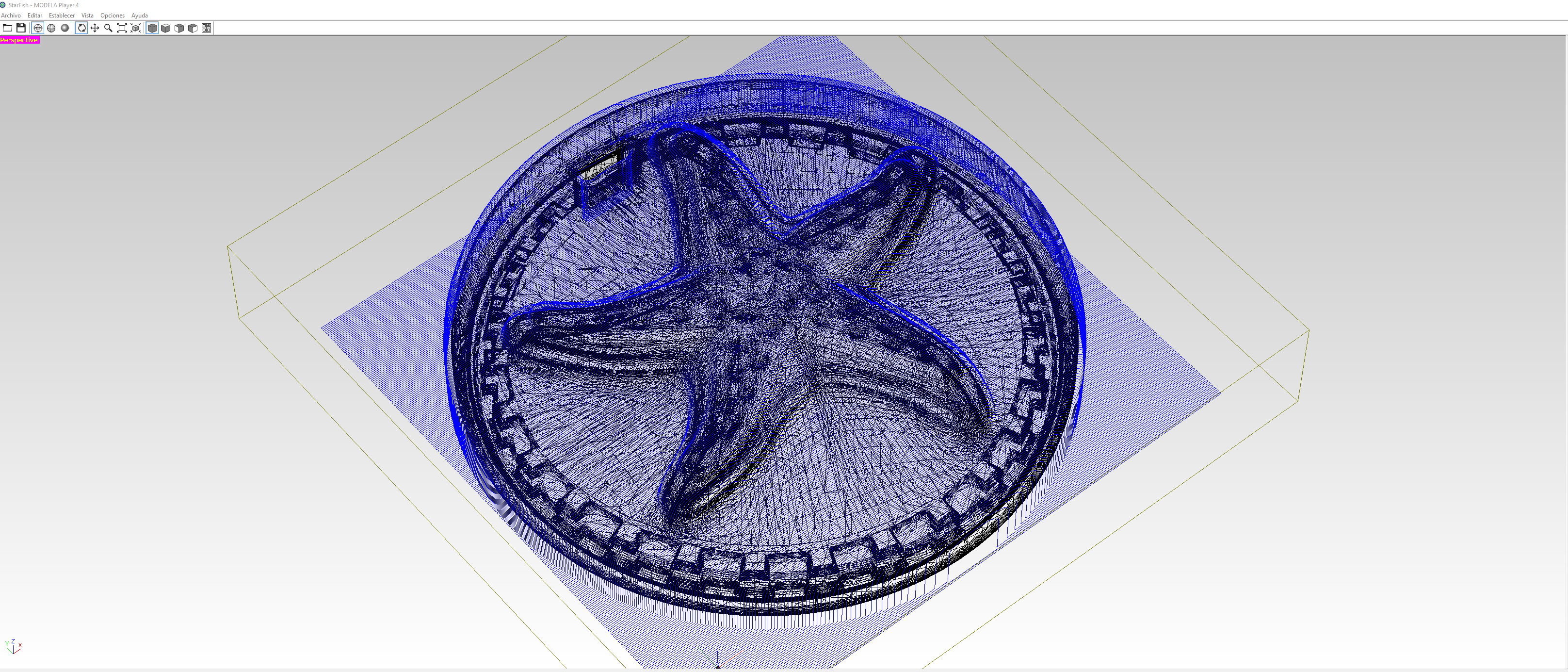
The CAM software used to obtain the machine code is MODELA Player 4, compatible with the Roland MonoFab SRM-20 (which will be the milling machine to be used). It is an intuitive software, and easy to use. After having some problems (which I will tell you about), I would recommend the following steps:
- 1. Select machine and work preferences (inches or mm)
- 2. Establish model. Its dimensions, axes and origin
- 3. Establish the modeling form. We choose edge sizes, depth and if we want a draft angle
- 4. Choose material and tool. If not already created, add them
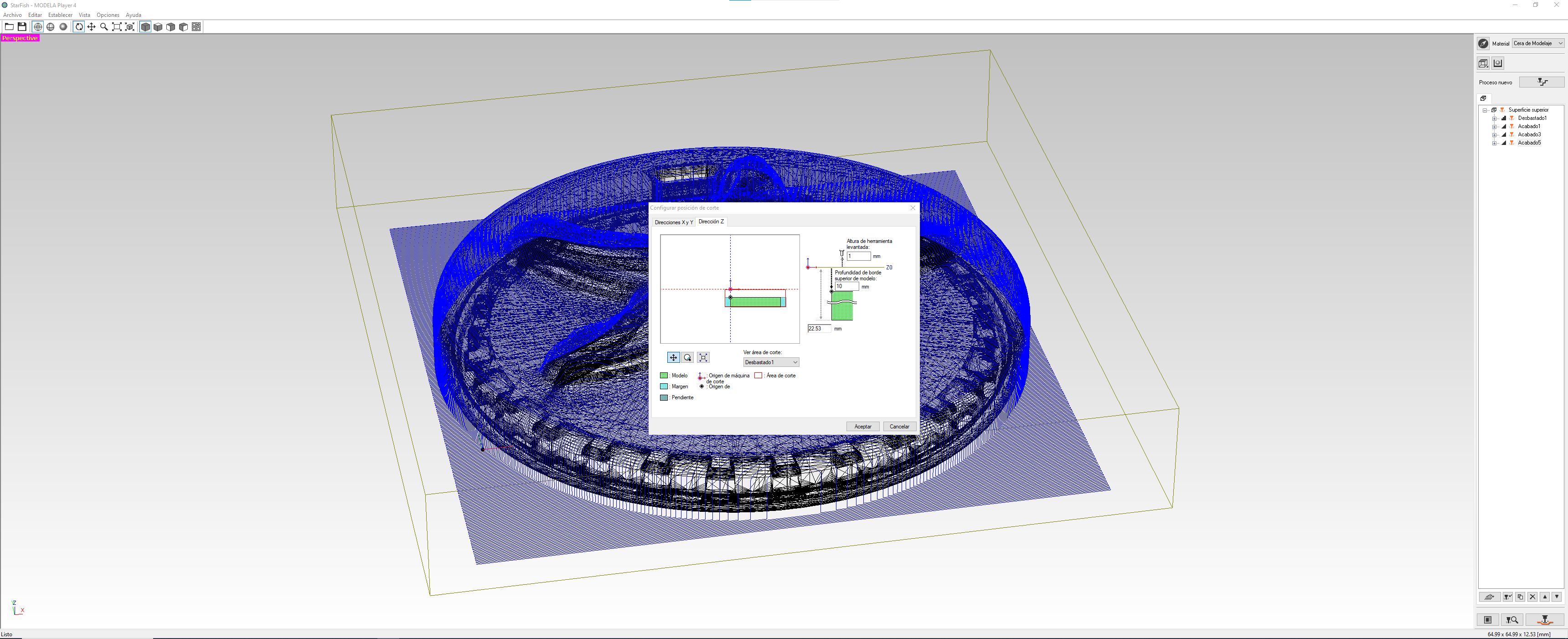
- 5. Check cutting position
- 6. Add cutting processes. Always at least one roughing and one finishing process.
In my first model, as I mentioned, there were no walls. This can be fixed from the program, modifying the work area and raising the machining start reference above the model.
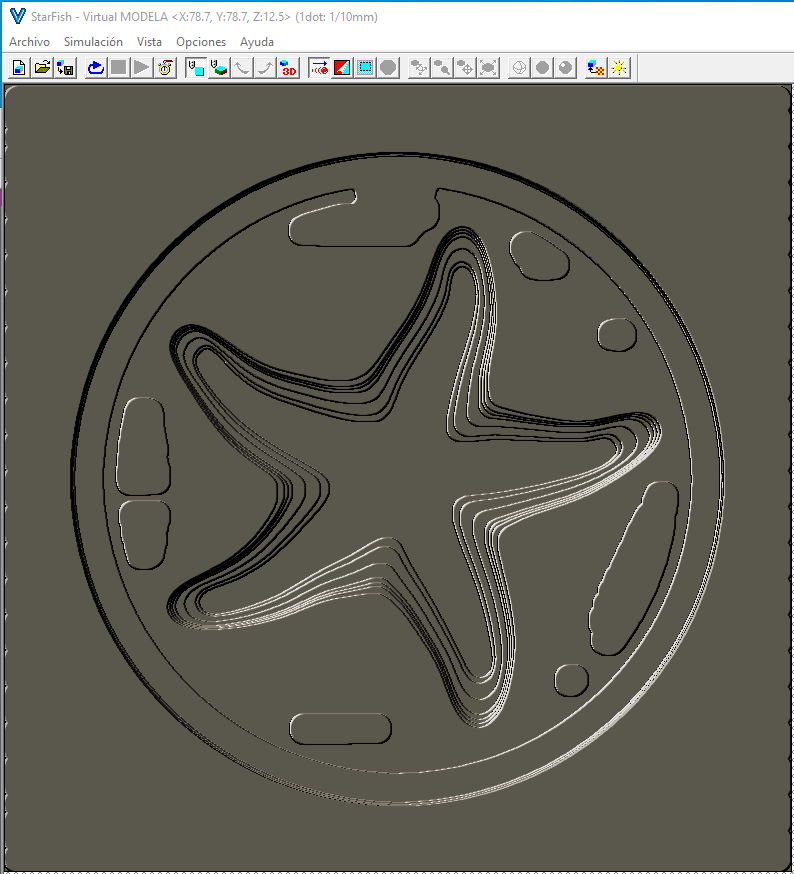
From the CAM result we can see the simulation in the Virtual MODELA program, where we can also know the machining times.
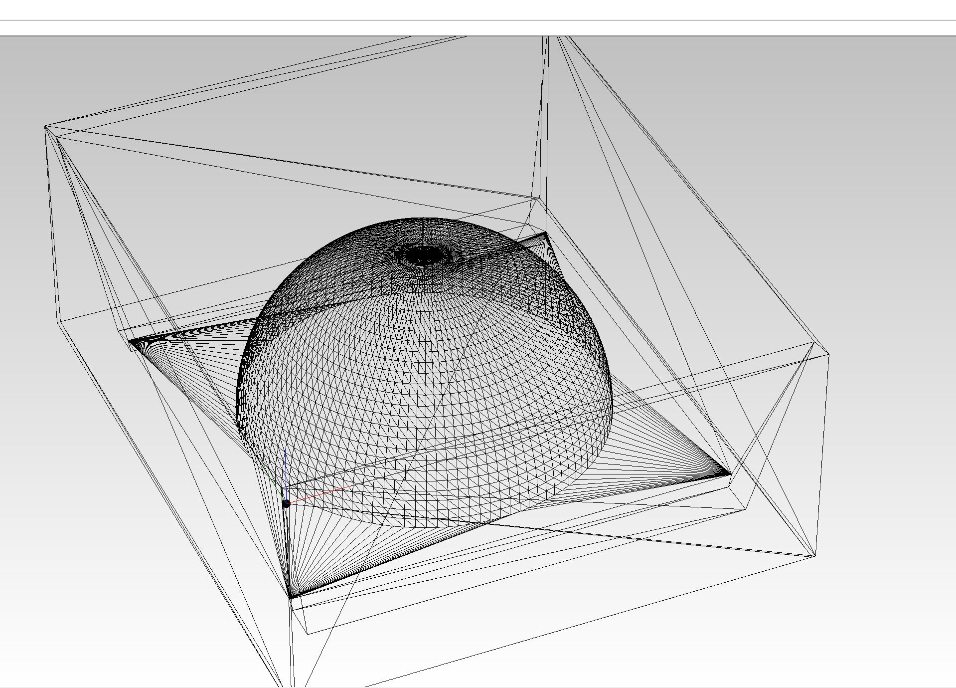
The second model to design is related to the final project. Somehow I wanted to incorporate part of the electronics (some LEDs) in the casted parts, but I didn´t want the electronics to be embedded without the possibility of changing them if necessary. Then, the intention is to generate a gap in the bottom of the model that will penetrate to include the necessary electronics.
Although the desin generated is not the same as the one will be used in the final project, the geometry is somewhat similar, so that it will be a convex surface at the top and it will have a hollow at the bottom. A generic model with these characteristics has been made to test the inclusion of the LED and can be interchangeable in case of failure or breakage.
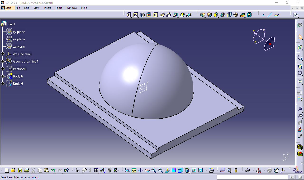
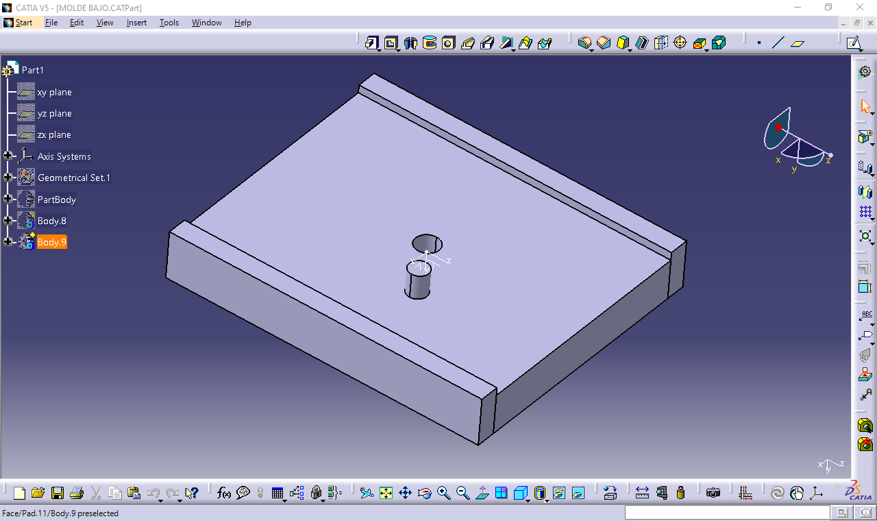
As you can see, a two-sided model has been chosen. I will explain later that it was not well designed (I did not take into account the hole for air evacuation). However, and as a recomendation, whenever the desin is made with two faces, it is preferable to design already contemplating the walls, since onde of the problems that were obtained was that the mold was quite deep and given the draft angle of 10º, the block was very tight and I had almost no space (very low wall thickness). Due to this fact, when I machined the first part of the mold, I used more than half of the wax block, so I had to readjust the second part of the model, making it shorter (it doesn´t affect the model as there was a lot of space for the silicone). This can be better seen in the following steps, when the two silicone parts of the mold are assembled.
In conclusion, I have designed two moulds:
- A one-sided mould. I have not designed a mould as such, but from the model and with the software used (MODELA player 4) I can generate walls upwards with an inclination and a top surface of a given width. Thus, we can make a simple mould.
- A two-sided mould. In this case the model was designed in two parts in Catia software. The fit between the two parts was taken into account, the filling hole and the overflow hole, but not the air evacuation hole.
Considerations for designing a mould
As I mentioned, not all the necessary considerations were taken into account when designing a mould. Thus, I will now indicate what needs to be taken into account before designing and manufacturing a mould:
Mould release considerations. The demoulding process must be taken into account when designing the two-sided mould. This includes the required demoulding angle.
Clamping mechanisms. This refers to how the two sides of the mould will be clamped or fitted together to prevent unwanted movement during curing of the final model.
Access to the tool. Consideration needs to be given to how the two sides of the mould will be accessed for machining. This may require the design of additional slots or openings, or the positioning or cutting of the part from the most suitable area. The overall depth of the part must also be taken into account and the demoulding angle must be taken into account to avoid collisions at high depths.
Filling considerations. It is important to place the air evacuation channel, and a hole for the overflow of material. In my design, I only considered one of the two holes. Later I will comment that I had to make the other hole manually.
Despite having made mistakes, in the final project in mind I must use transparent parts (something similar to what was done in the two-sided mould) and I will have to design and manufacture new moulds.
Machining
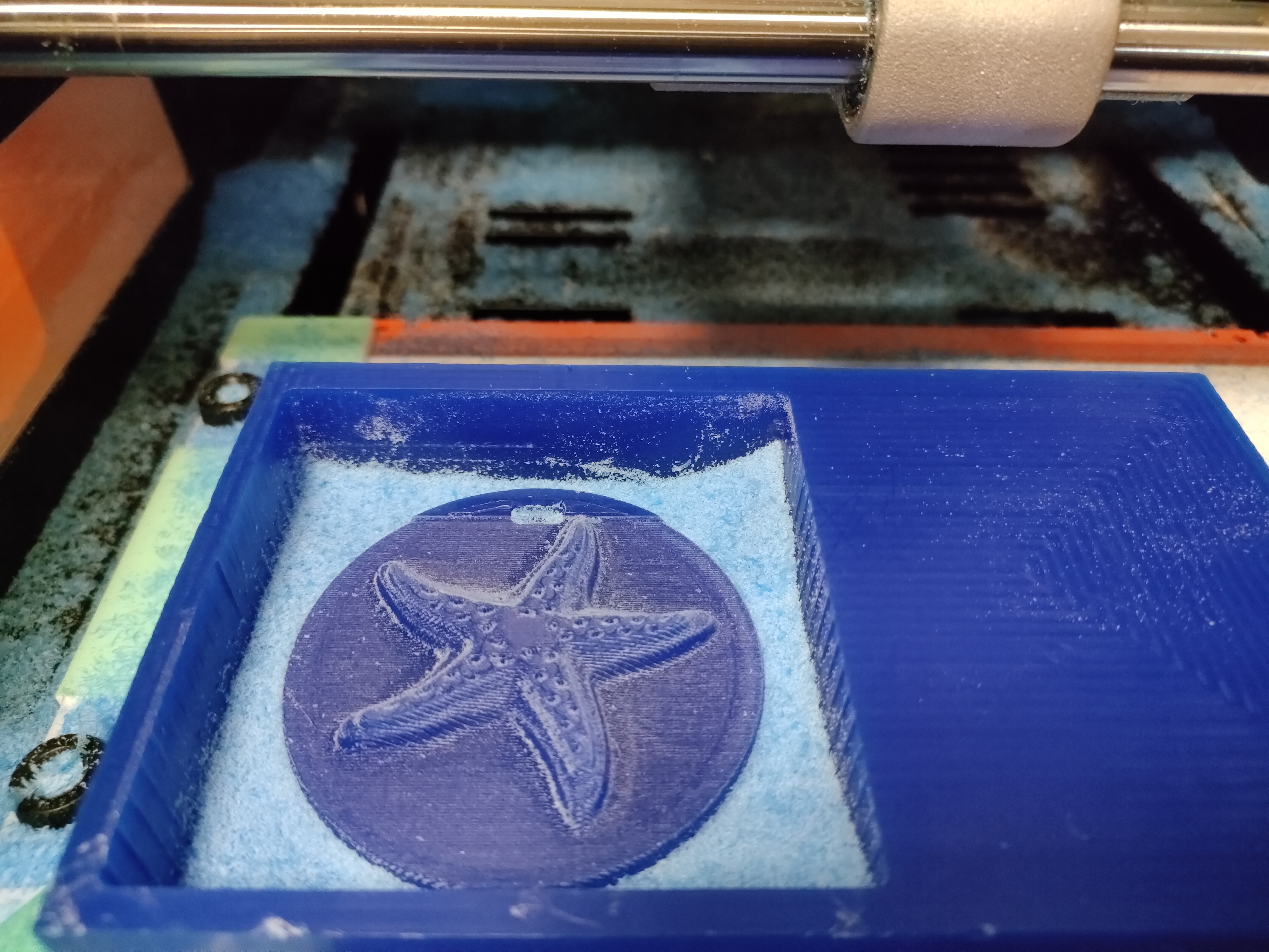
With the CAM documents I was able to go to the machine to machine the models. The milling machine used again is the Roland monoFab SRM-20.
The material to be machined is a blue (for the one-sided model) and a green (for the two-sides model) ferris wax.In this case, and given how tight we have the size of the mold in our starting material block, the 0 part has to be made with greater precision.
One of the main errors obtained with the generated code was that a roughing operation was performed with the 3.2 mm tool and a finishing operation with the 1 mm milling cutter. The model had a hole smaller than 3.2 mm in which the tool in the roughing operation was not able to penetrate. Thus, when the 1 mm milling tool (of low quality) went to perform the finishing operation, it penetrated excessively and all at once into the material, producing the catastrophic failure or fracture of the tool.
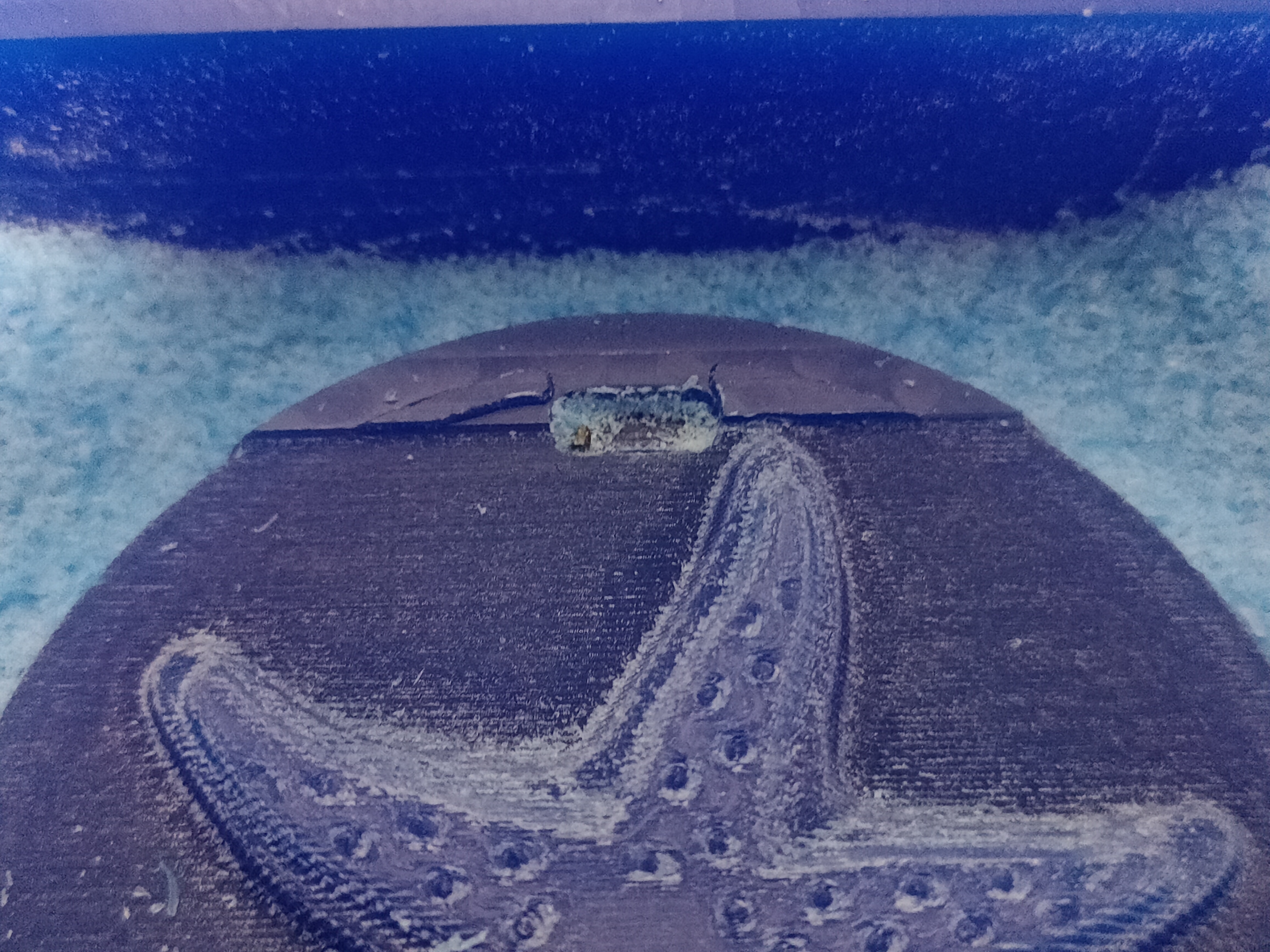
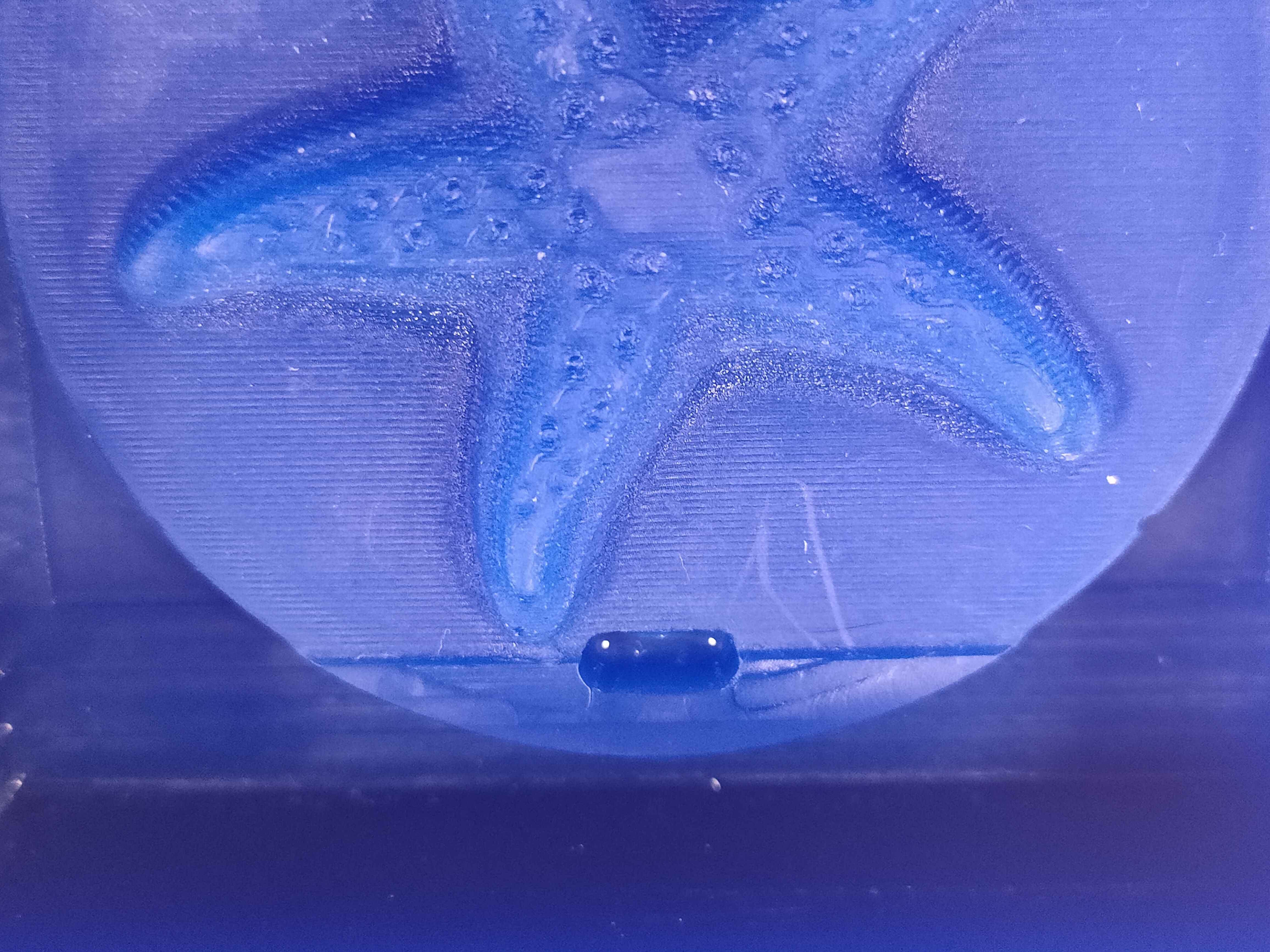
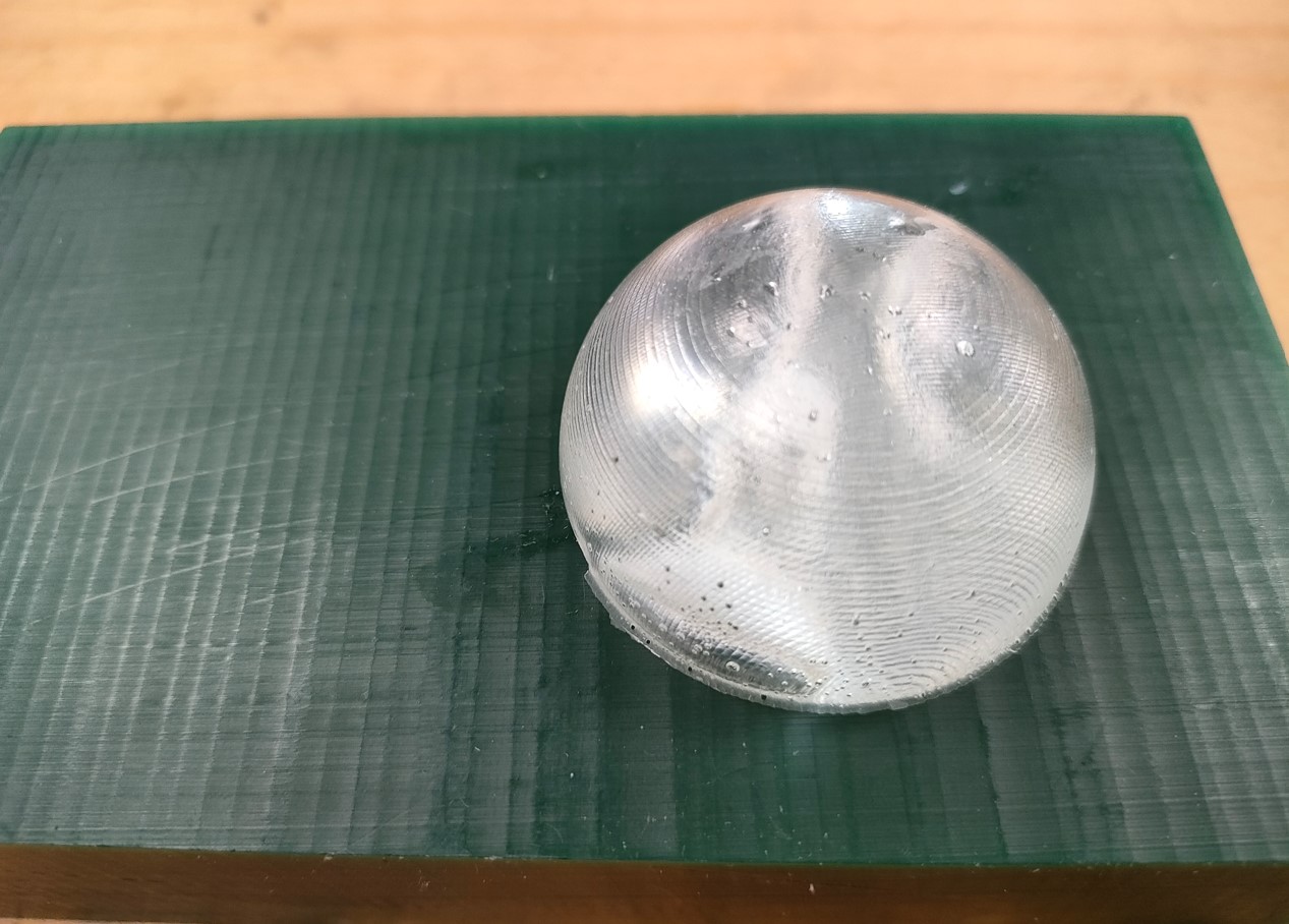
The embedded tool was removed and a new roughing and finishing was performed only in the area of the hole (and the rest that was missing), this time with the 1.6 mm tool. In the figure it can be seen that even working with a larger diameter tool, the surface finish is better than with the 1 mm tool.
This change in quality will affect the final model. It could be solved by giving a new finishing pass to the entire surface. However, it was considered interesting to see the different qualities or textures that we can achieve depending on the milling done.
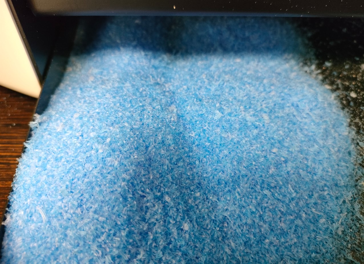
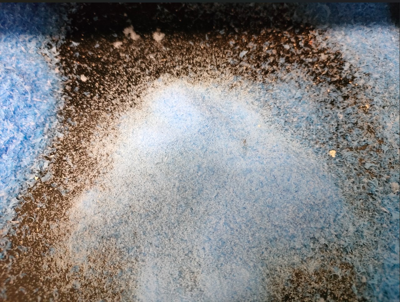
It is interesting to compare the two types of chips obtained in this machining, on the left the chip obtained in roughing and on the right in finishing, the latter being much thinner.
In the following videos we can see how the roughing (on the left) and finishing (on the right) operations are performed in the second mold.
In this case, the same mistakes were not made as for the first mold, but others arose. Among them, the area of the first part of the mold to be machined was not well calculated (since the demolding angle and the cutting area are located in the upper part of the model, and not in the fictitious upper part to be machined). Hence the previous recommendation to design the model with the walls already included.
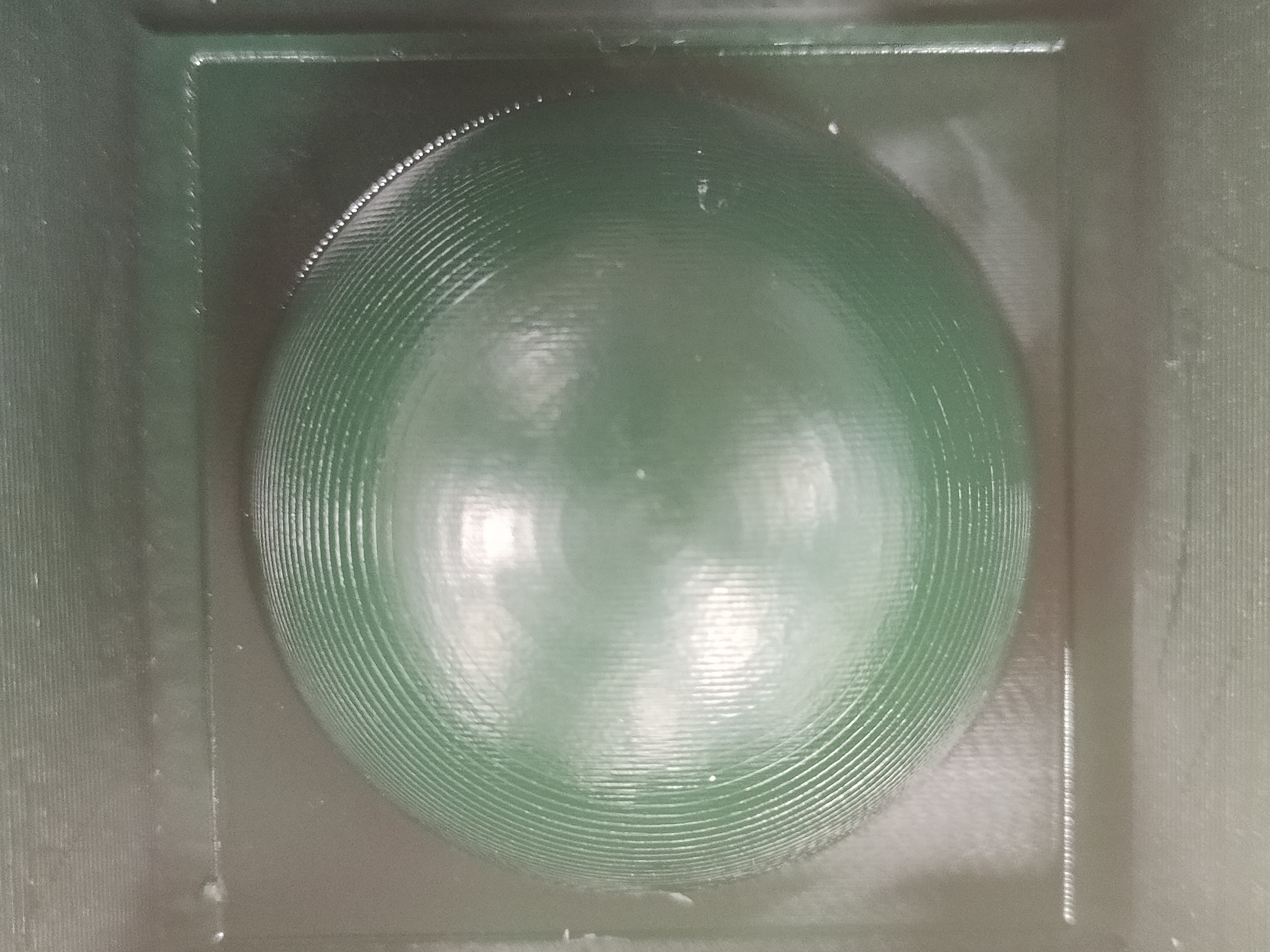
For this reason, as you can see in the pictures, one of the mold walls was too thin. In addition, the size of the second side of the model had to be readjusted to fit the wax block to be machined.
The quality of the finishing operation is quite good, although I also recommend for improvement the use of scan line finishing in both X and Y axes (it was used only in X to reduce machining times).
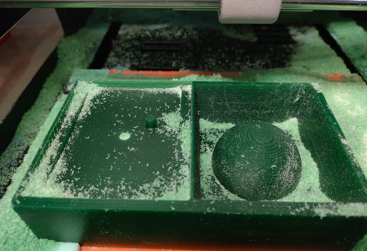
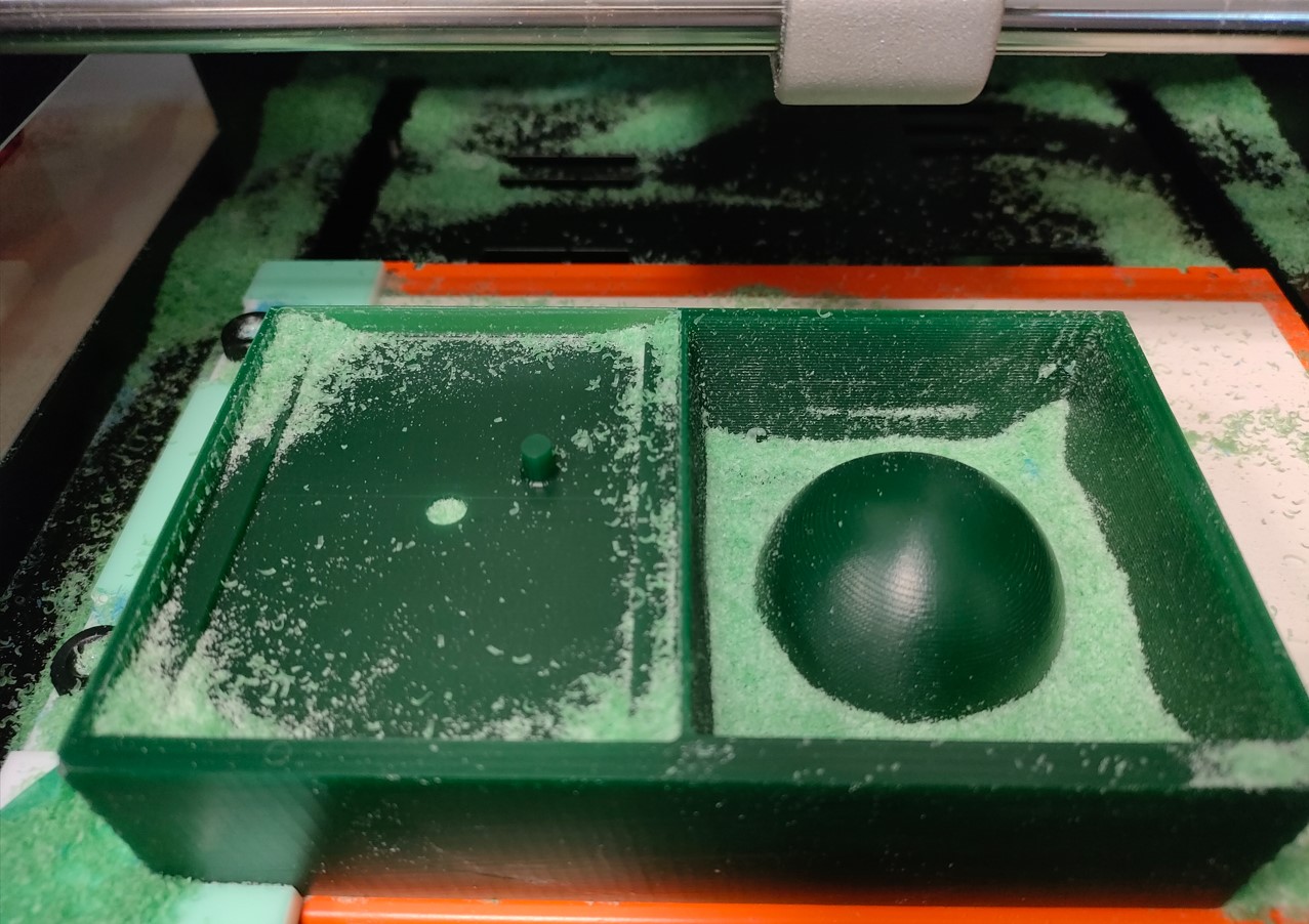
The following figure shows the different finishes obtained with the tools used. On the one hand, mold 1 (the star) was roughed with the 3.2 mm diameter tool and then finished with the 1 mm diameter tool. This tool was split at the top part.
For the second mold, the 3.2 mm tool was used directly for roughing and the 1.6 mm tool for finishing. However, since it is a convex geometry, the finishing should be done on both axes for a finer surface finish. However, the finish with the second tool is better (round tip tool with 1.6 mm diameter) than the finish in the first mold (with the 1 mm diameter tool). I think this is mainly because the 1.6 mm tool is round tipped and the 1 mm tool was flat. Also, being of larger diameter and having almost the same cutting parameters (feed rate) and the same rotational speed, the tangential speed at the cutting point is higher, evacuating more chips per unit of time (smaller chips can be related to better finish).
Mold creation / Silicone casting
With the models made, I was able to create my silicone molds.
There are different types of silicone. In this case, Feroca´s PLATSIL FS-20 was used. The table with the main characteristics of the material is below. They are two low viscosity resins that react when mixed. Therefore, they must be mixed well in the ratio indicated in the technical data sheet (in this case the ratio is 1:1) and stirred in several directions and quickly (since the resin has a generally low working time, in this case 8 minutes).
| Mixing ratio | Hardness | Pot life | Demold time |
|---|---|---|---|
| 1A : 1B | Shore A20 | 8 min (25ºC) | 25 min (25ºC) |
Once they are well mixed, it should not take long to pour the contents into each model. Ideally, a little vacuum should be applied to the mixture to eliminate most of the bubbles. However, we do not have a vacuum machine, so I had to skip this step.
Pouring should be done slowly, always dropping a thin stream over previously deposited material, to try to eliminate bubbles as much as possible.
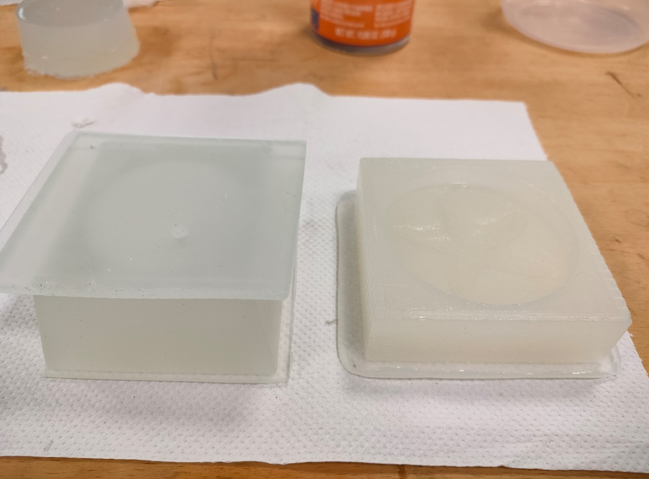
Once all the material has been poured, it is only necessary to wait for the molds to solidify. The reaction time for the material used is 25 minutes, although we waited 1 hour before removing both molds from their respective models.
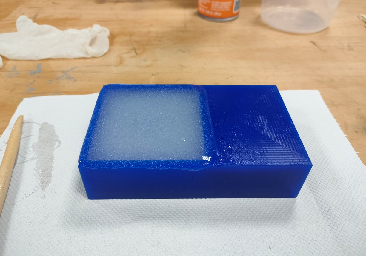
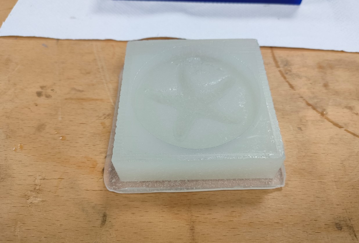
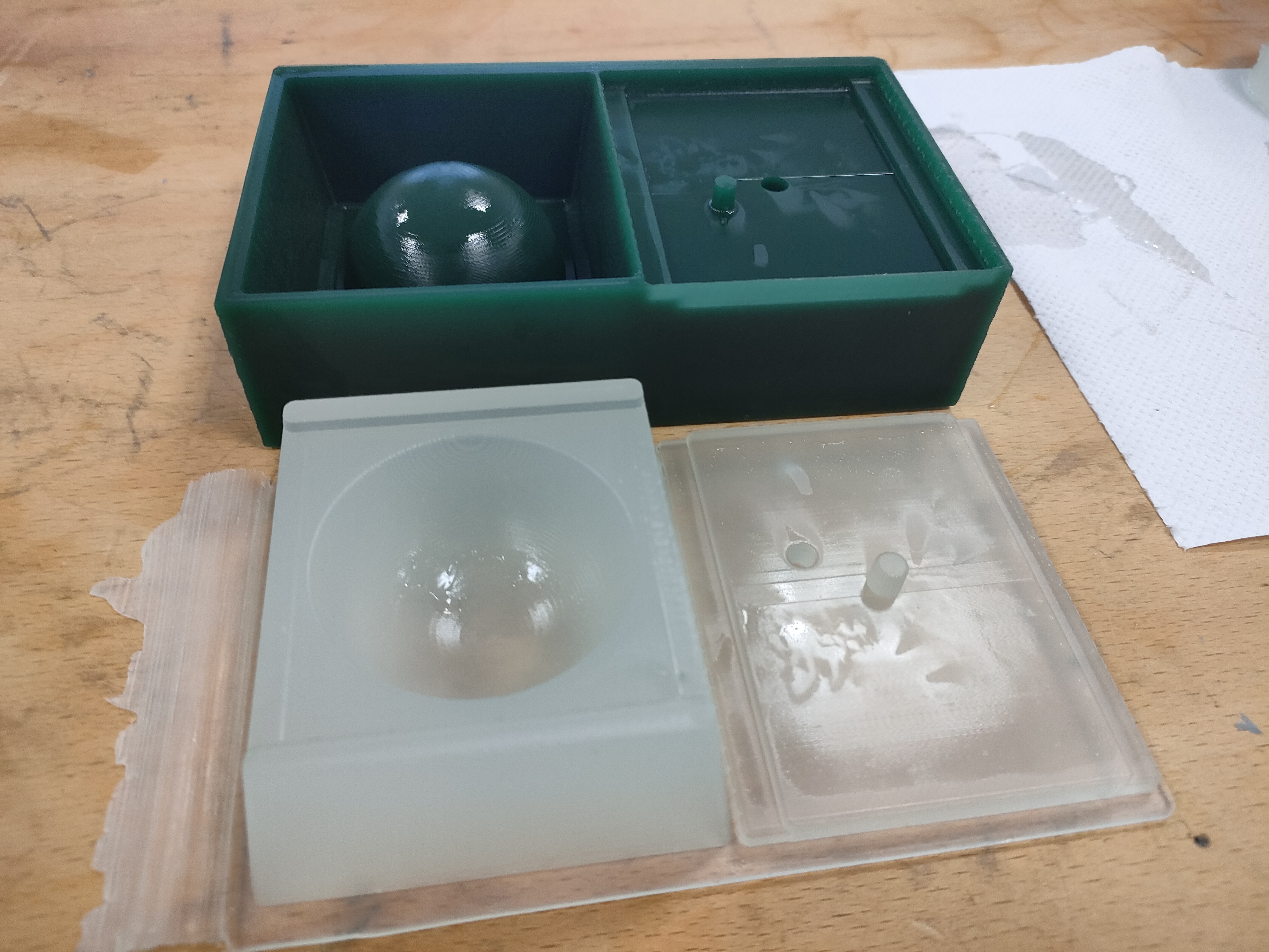
The surface finish of the models is faithfully reproduced on the molds. In the case of the defects that my model 1 had due to the breakage of the tool, there is a small jump or change of surface finish in the area that can be noticed perfectly. For mold 2, you can clearly see the area where the finish was made and the one that was left only with the roughing operation.
This means that if we want a thinner part or with better tolerances, we have to take this into account from the initial machining phase.
Final model
When the molds are finished, a silicone release agent must be applied to the entire surface (and to both surfaces in the case of a double-sided mold).
Then, the material for the final model must be prepared. In my case, I used an epoxy resin. This resin must be mixed in a ratio of 100:60 by weight and special care must be taken because the two components do not have the same density (we cannot measure by volume).
| Mixing ratio | Pot life | Demold time |
|---|---|---|
| 100A : 60B | 20 min (25ºC) | 24-48 h (25ºC) |
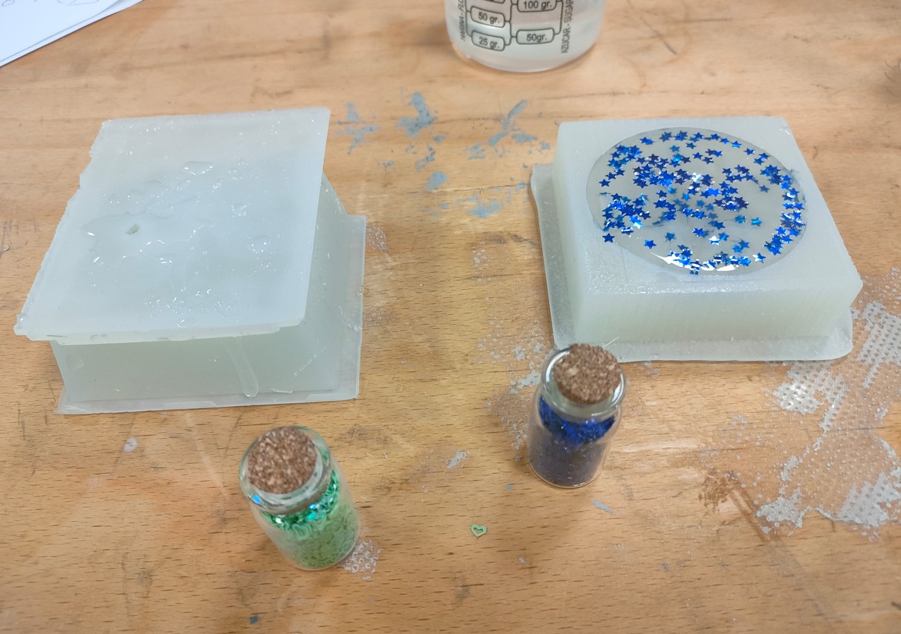
One of the models was designed to integrate embedded glitter. This is because in the final project they want to make some areas of the product with colored paper or glitter, as it is a product intended for children.
This resin generates an exothermic reaction, so we can observe even more bubbles than in the process of creating the mold.
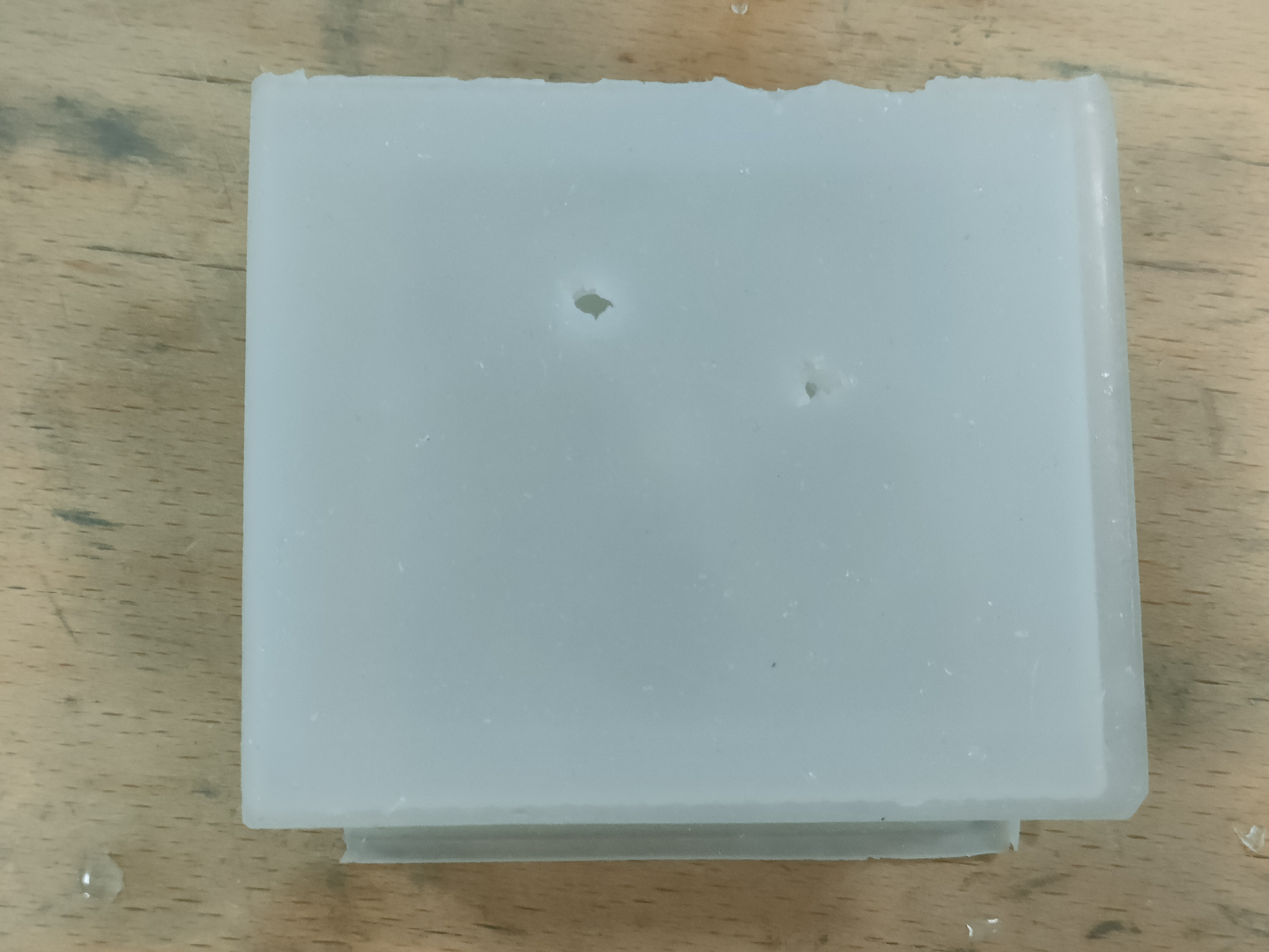
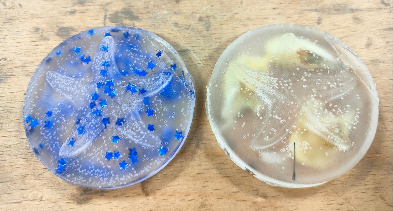
Initially, since the curing time is 24 to 48 hours, it was thought that bubble evacuation would be quite simple. However, we can see the first results:
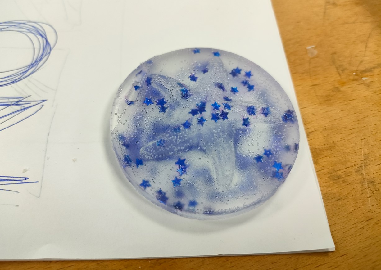
It can be seen that both models are full of bubbles. In addition, the glitter was not evenly distributed throughout the piece. In mold 2, a clear filling defect can be seen, as well as a bad air evacuation. This was mainly due to two reasons: not having made an air evacuation hole and not having made the pouring hole larger. Thus, it was decided to manually drill a hole to facilitate air evacuation.
A second test with the same molds and material was desired. On this occasion, since there was no vacuum chamber available, we tried to vibrate the glass to favor the evacuation of bubbles. It was also slightly heated to excite the air particles so that they could come out faster. Care must be taken not to heat the resin too much, as this accelerates the reaction. In this case the resin has a 24-48 hour cure time, so there are no problems.
Once I saw that most of the bubbles had evacuated, I proceeded to pour again. For the 2-sided mold in this case, it was filled open, and the top was placed to make it overflow. This method is not the most suitable for eliminating bubbles. It is recommended that if there is an error in the model like mine (small filling channel and/or non-existent air evacuation channel), it should be done manually.
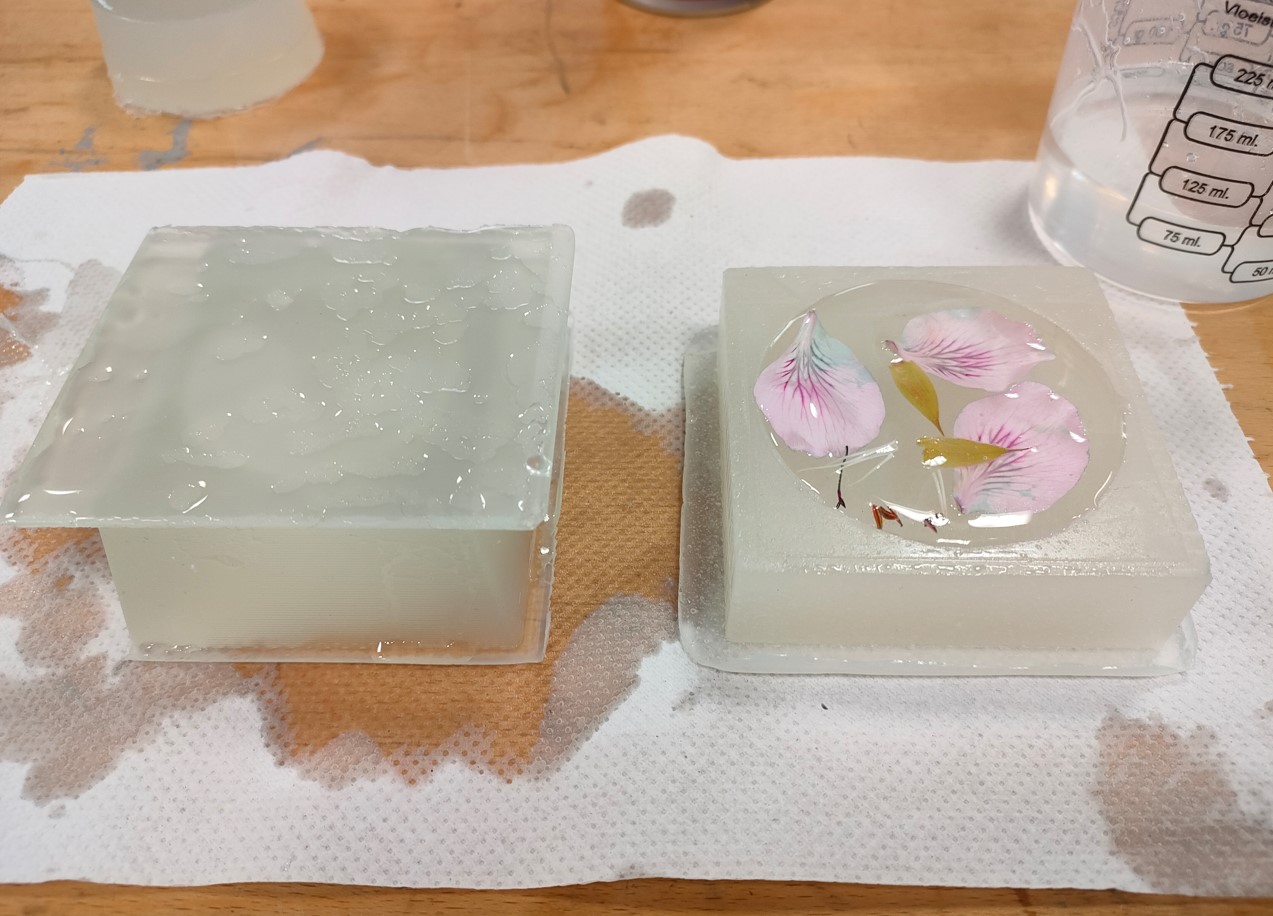
In the second test, flower petals were placed on one of the models. These were placed on the upper part, which will be the base of the model, to ensure that they do not fall to the bottom.
Once the curing period was over, the models were demolded again.
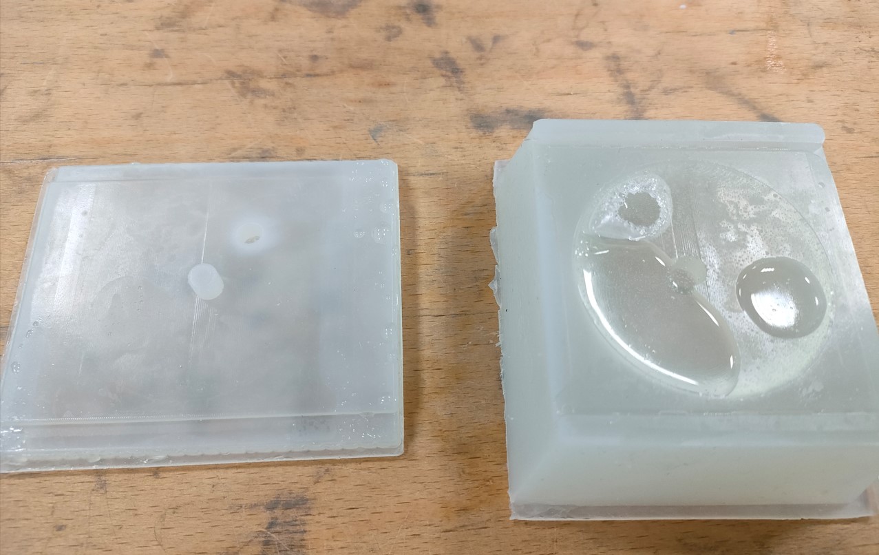
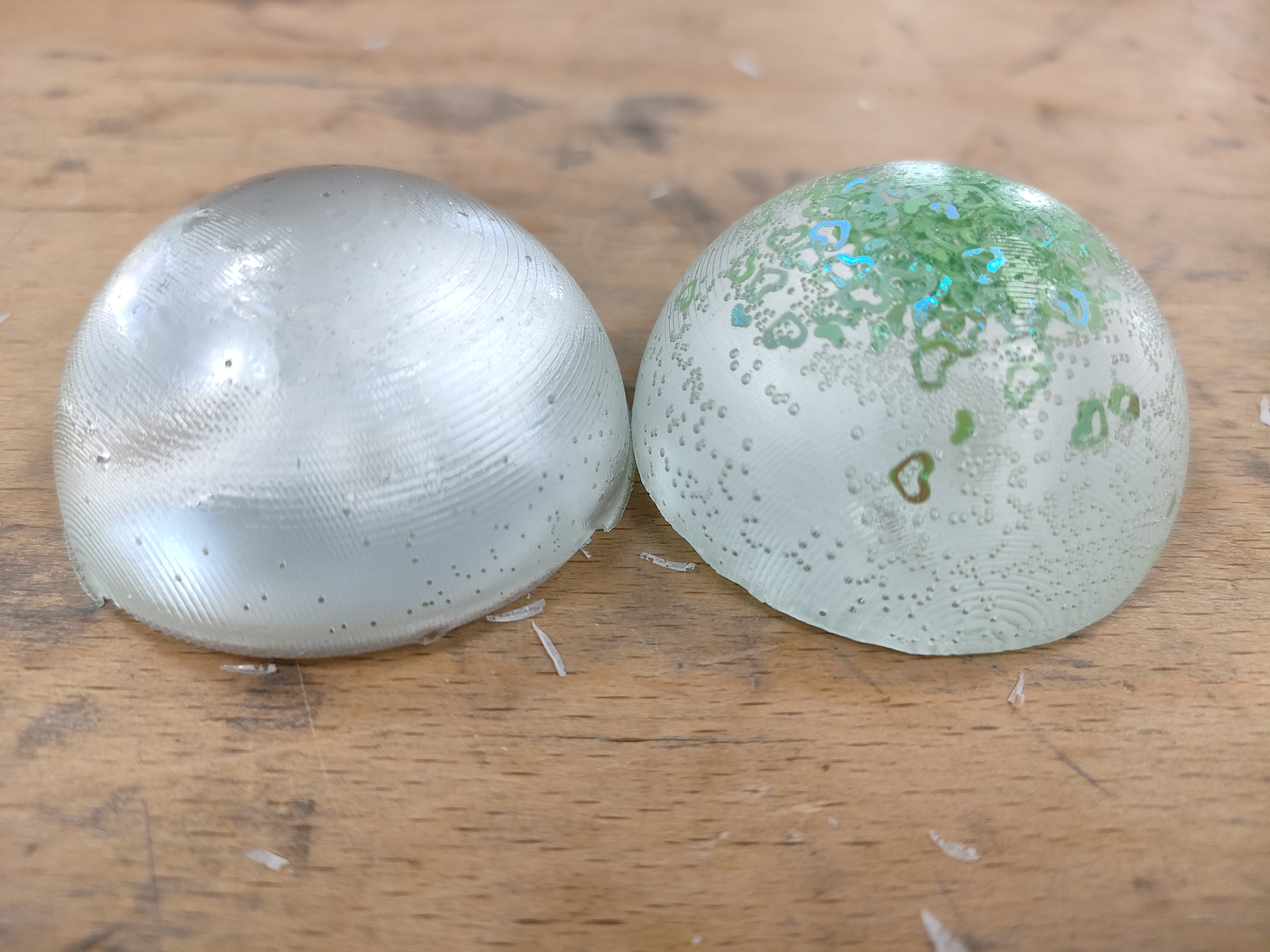
On this occasion, better results were observed than previously. However, the two-sided model was repeated again to not include glitter in it.
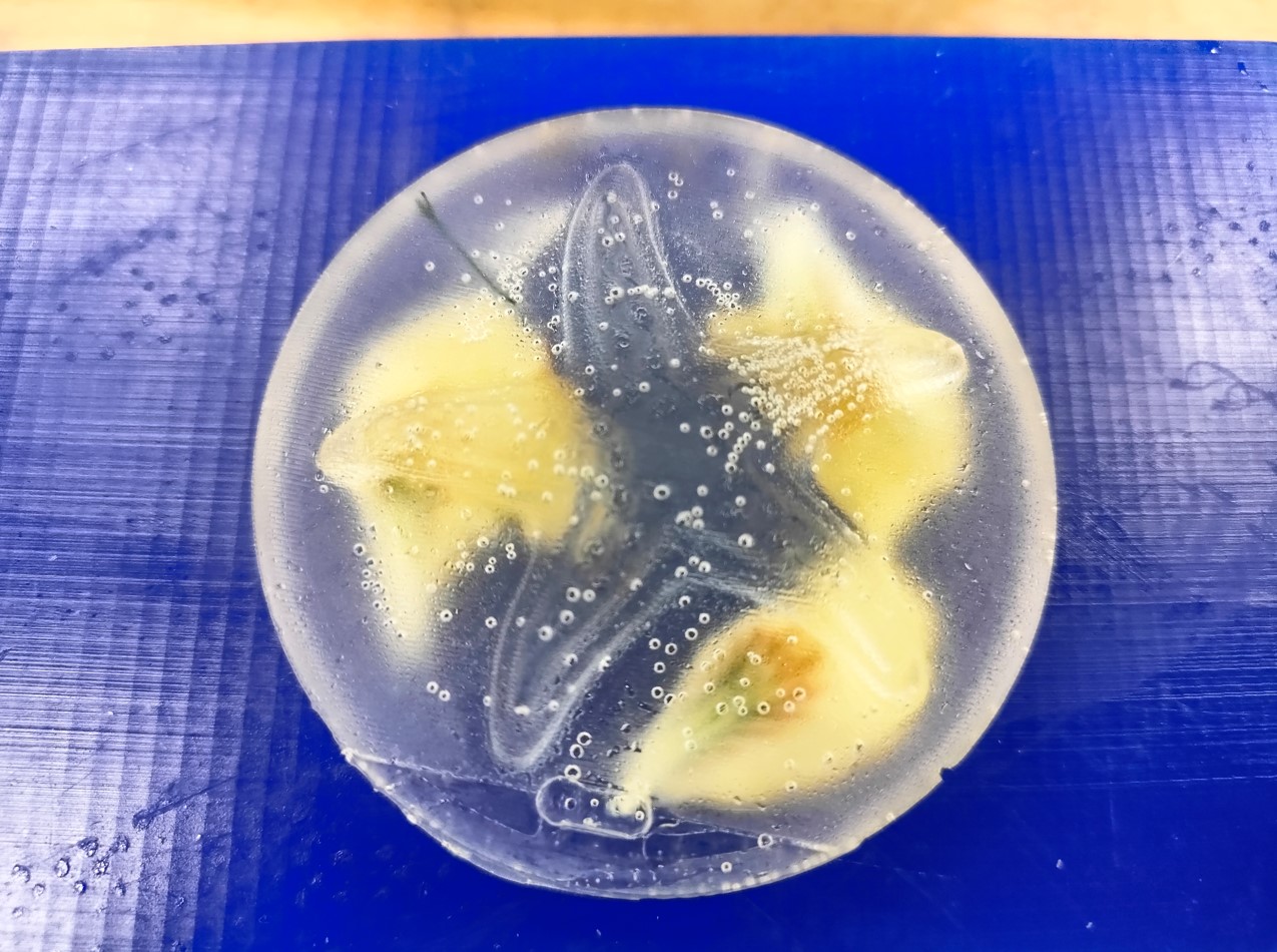
You can compare the designs and see the difference in the amount of bubbles. Bbuble removal has been considerably improved with vibration and heating after the mixing process. However, it is still not sufficient to remove all bubbles. It is therefore recommended to have a vacuum chamber and it is proposed to assemble/purchase one for future occasions.
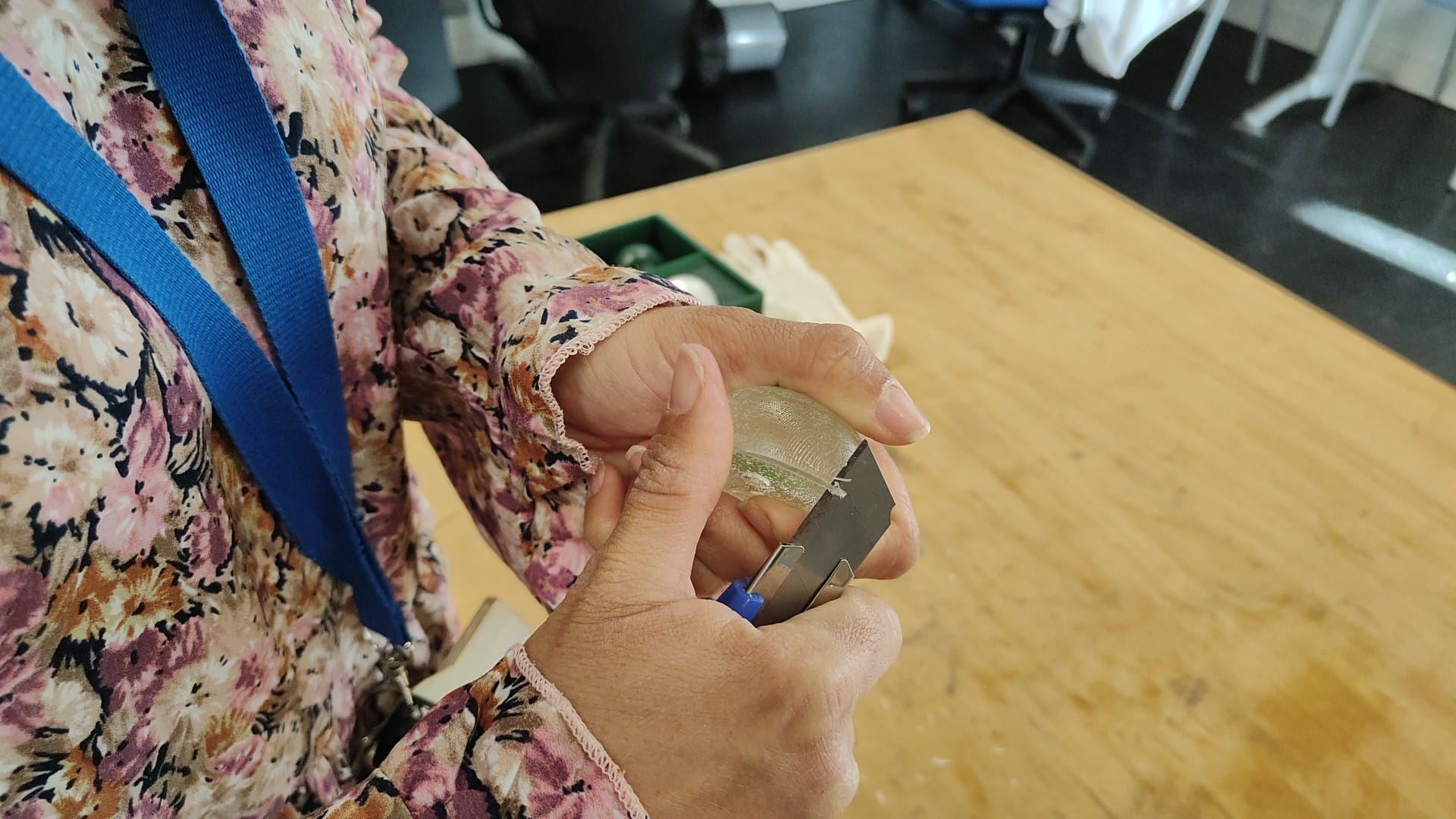
The edges generated with the overflow of the material were cut with a cutter (without much caution). It would also be interesting to give some kind of finish to the piece, or to the mold itself, so that the surface would have a better finish.
Safety precautions
It is advisable to consult the technical data sheet before using any material. In the case of silicones and resins, in all cases it is recommended the use of gown and gloves, as well as to have a good ventilation in the room. In addition, it is recommended (although I have not made use of it) to use goggles and a mask.


In addition, most of the chemicals used in this field are flammable and dangerous when in contact with the skin. It is also recommended to have your hair tied back (if you have long hair) and not to have any hanging elements (necklaces or similar).


Group assigment
This week we probe an input device(s)'s analog and digital signals. The group task can be viewed at Group Assigment page.
Files
The starfish model.
The first part of the two-parts mold.
The second part of the two-parts mold.
The first part of the two-parts mold-original model (catia).
The second part of the two-parts mold-original model (catia).
Conclusions
This week we have learnt how to design and manufacture molds to reproduce castings.
The model design process is one of the most important. Especially the starting material and the tools to be used have to be considered before designing a model. In addition, for deep molds, the draft angle must always be kept in mind so that the tool can reach the lower areas of the mold without touching tue upper ones or the walls with the tool handle.
It is also important in double-sided molds to include a pouring hole and a different hole for air evacuation (although it may seem absurd. I forgot one of them).
For the mold and model creation process, it is recommended to mix for several minutes before starting the poruing process to ensure taht both components are well mixed. In addition, if you don´t have a vacuum chamber, it is recommended to vibrate the mixture and heat it slightly to encourage the evacuation of bubbles.