12. Input Devices
This week we learned about the types of inputs there are and how to use them. We had to add at least one sensor to a microcontroller board we designed and read it.
Although I still had doubts about the final work, I wanted to test with a proximity detector and a contact detector.
For the proximity detector, I thought of trying the grove ultrasonic ranger. This is a non-contact distance measuring sensor (see the image).
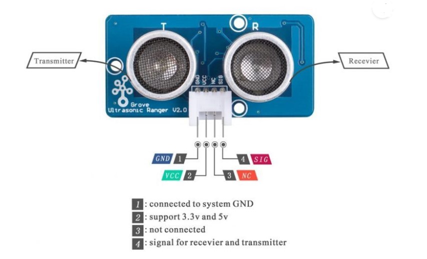
This sensor contains two transducers, one acts as a transmitter of a sound signal at 40KHz and the other acts as a receiver. When the receiver captures the signal it produces a pulse that serves as a reference to determine the distance the signal traveled.
Subsequently we will have to interpret this time as a distance:
Speed = distance / time
Some of its technical characteristics are:
- Operating voltage: 5 V
- Operating current: 15 mA
- Operating frequency: 40 KHz
- Maximum / Minimum detection range: 4 m / 2 cm
- Trigger signal: 10 µs
- Dimensions: 45x20x15 mm
So, having designed the board in outputs week, I designed a new board for this week in KiCad.
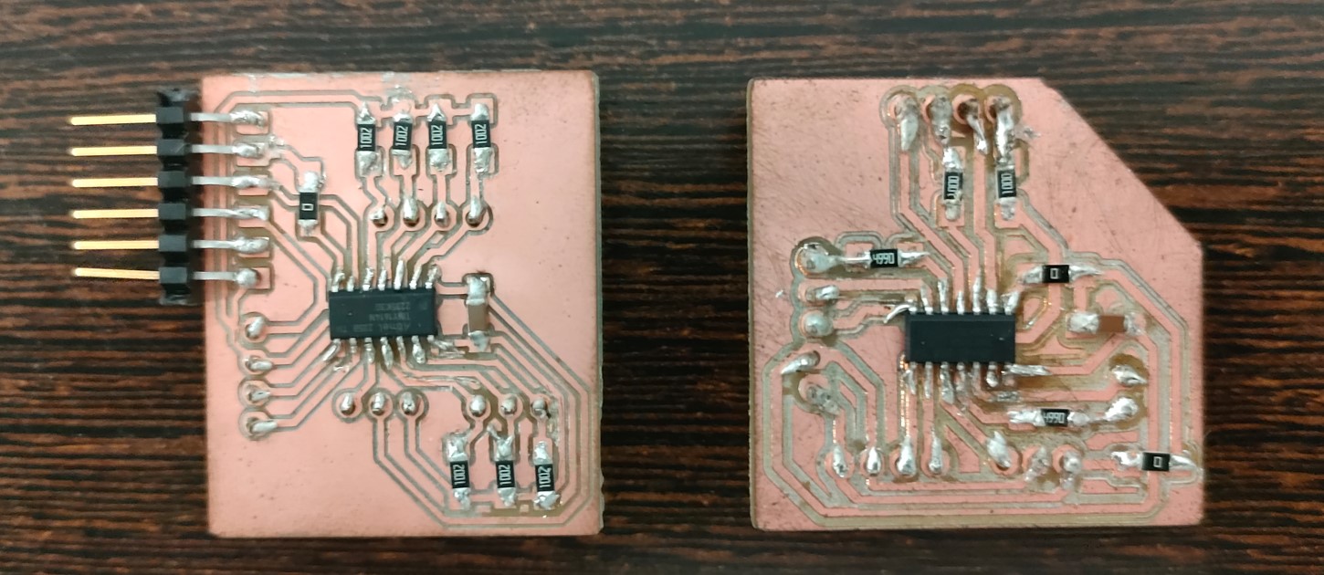
This board was designed with a view to the final project. Actually one was made, and then modified. Below are the images of the first one on the left and the final one on the right.
The pins used for the first case are marked on the first board. The pins used in the final project test are marked on the final board.
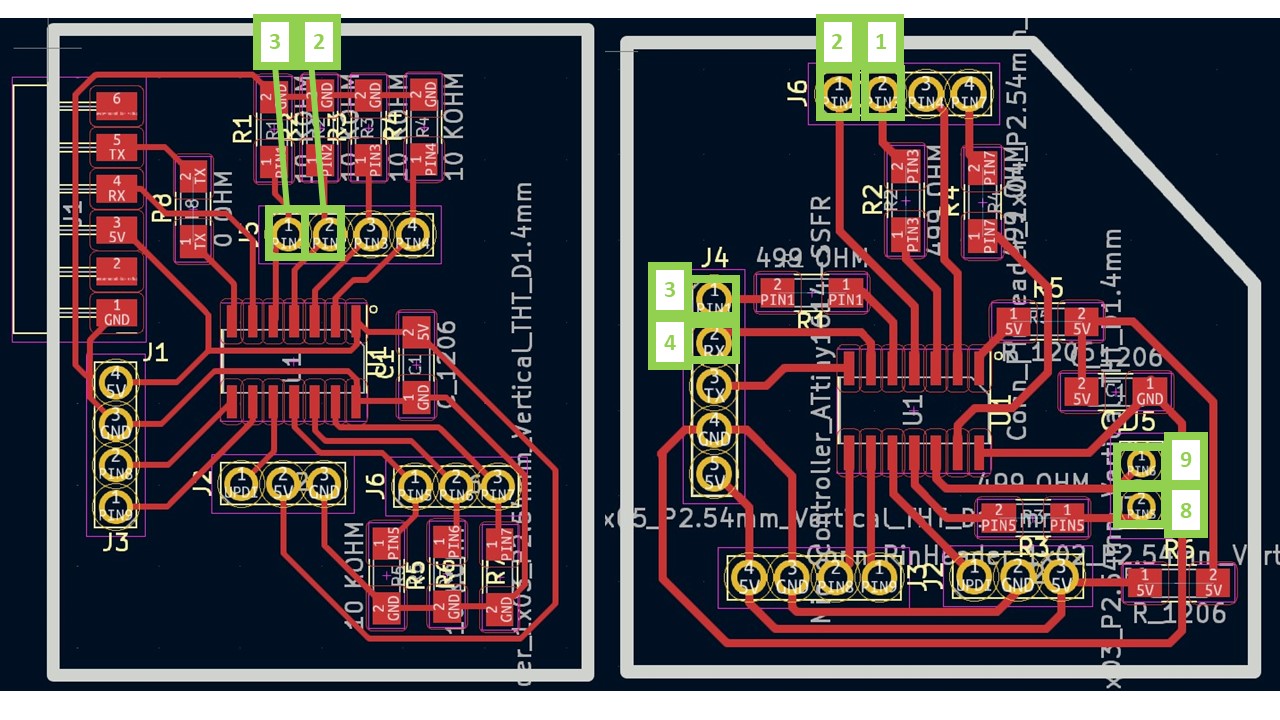
In the case of the distance sensor I need 2 analog pins, ground and voltage. In the case of my final project I need 2 pins for each triangle to be used (initially 3 triangles were used, equivalent to 6 pins), ground and voltage. Also in both cases I need the UPDI pin for programming.
For this board (in both cases) I wanted to use a different microcontroller than the previous ones, the ATtiny 1614.
This microcontroller cannot be controlled directly with the computer. Thus, it needs a bridge board to be able to program it, and in this case also to power it. To do this, download the UPDI bridge which is on GitHub (UPDI and modified UPDI) and is shown below:
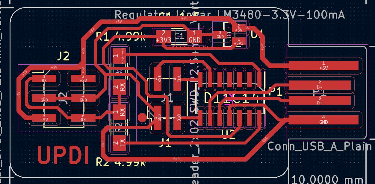
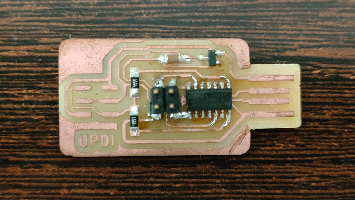
Simply connect 3 of the wires (they are duplicated) from the jumper board with their 3 counterparts on my designed board (GND, 5V and UPDI). These pins on my designed board can be seen to be in the lower right area.
A simple code has been tested to check and print values when placing and removing the hand on the sensor, taking distances with value 0 - X cm.
const int Trigger = 3;
const int Echo = 2;

int tiempo;
int distancia;

void setup() {
  Serial.begin (9600);
  pinMode(Trigger, OUTPUT);
  pinMode(Echo, INPUT);
  digitalWrite(Trigger, LOW);

}

void loop() {
digitalWrite(Trigger, HIGH);
delayMicroseconds(10);
digitalWrite(Trigger, LOW);
tiempo = pulseIn(Echo, HIGH);
distancia = tiempo/59;

Serial.print("Distancia: ");
Serial.print(distancia);
Serial.println(" cm");
delay(100);

}
In the video you can see the values printed on the arduino.
When we started the code we noticed that something was wrong. It only marked 0 when it was not properly connected, but the values did not seem to agree with reality.
So, I checked the documentation and found that I had programmed the input with respect to a previous version in which both pins were required. For this new version, there is one pin (as it was in the previous schematic) that is not connected. With the other one, and an Arduino library (Ultrasonic ranger Library) that we can download and install, we can test again the functionality of this input.
With this library, calculations are no longer necessary, and we can directly compile the following code:
          #include "Ultrasonic.h"

          Ultrasonic ultrasonic(3);
          void setup()
          {
           Serial.begin(9600);
          }
          void loop()
          {
           long RangeInCentimeters;

           Serial.println("The distance to obstacles in front is: ");
           RangeInCentimeters = ultrasonic.MeasureInCentimeters(); // two measurements should keep an interval
           Serial.print(RangeInCentimeters);//0~400cm
           Serial.println(" cm");
           delay(250);
          }
So by moving the hand closer and further away from the sensor, we would get on screen what you see in the video below:
The problem was found that the sensor was not soldered to the board, but it was a test with the free pins of the barduino, so the sensor did not make good contact, so the values sometimes danced. However, since it is a very cheap and easy to use sensor, it gives the expected results.
On the other hand as mentioned before, I wanted to test a magnetic contact sensor. A Hall effect sensor takes advantage of the Hall effect, which can occur in a metal or a semiconductor. This effect is based on the basic interaction between an electron and a magnetic field.
However, I did not have this sensor available, so I decided to use another item that was of interest to me.
I work in manufacturing processes and one of the important things is to have temperature control. So, I decided to use a digital thermocouple that has sensing and is compatible with my board.
So I chose the MAX31855 which has a temperature measurement range of -200°C to +1350°C.
So, I made a code that detects the temperature and in a range turns on a green, yellow or red LED depending on the temperature rise.
In this case, and because the other board was not available, I used a commercial board as I just wanted to check how it worked and if it was going to be useful in the near future.
The code used can be seen below:
#include#include "Adafruit_MAX31855.h" // Definición de los pines de los LEDs #define LED_VERDE 53 #define LED_AMARILLO 51 #define LED_ROJO 49 // Definición de los umbrales de temperatura #define UMBRAL_VERDE 50 #define UMBRAL_AMARILLO 60 // initialize the Thermocouple Adafruit_MAX31855 thermocouple(52, 50, 48); // Pines MAXCLK, MAXCS, MAXDO void setup() { Serial.begin(9600); while (!Serial) delay(1); // Esperar por la conexión serial en Leonardo/Zero, etc. Serial.println("MAX31855 test"); // Esperar a que el chip MAX se estabilice delay(500); Serial.print("Inicializando el sensor..."); if (!thermocouple.begin()) { Serial.println("ERROR."); while (1) delay(10); } // Configurar el modo de los pines de los LEDs como salida pinMode(LED_VERDE, OUTPUT); pinMode(LED_AMARILLO, OUTPUT); pinMode(LED_ROJO, OUTPUT); Serial.println("DONE."); } void loop() { // Leer la temperatura actual double c = thermocouple.readCelsius(); if (isnan(c)) { Serial.println("¡Se detectó un fallo en el termopar!"); uint8_t e = thermocouple.readError(); if (e & MAX31855_FAULT_OPEN) Serial.println("FALLO: El termopar está abierto - sin conexiones."); if (e & MAX31855_FAULT_SHORT_GND) Serial.println("FALLO: El termopar está en cortocircuito a GND."); if (e & MAX31855_FAULT_SHORT_VCC) Serial.println("FALLO: El termopar está en cortocircuito a VCC."); } else { Serial.print("Temperatura actual (°C): "); Serial.println(c); // Control de los LEDs según la temperatura if (c < UMBRAL_VERDE) { digitalWrite(LED_VERDE, HIGH); // Encender LED verde digitalWrite(LED_AMARILLO, LOW); // Apagar LED amarillo digitalWrite(LED_ROJO, LOW); // Apagar LED rojo } else if (c >= UMBRAL_VERDE && c <= UMBRAL_AMARILLO) { digitalWrite(LED_VERDE, LOW); // Apagar LED verde digitalWrite(LED_AMARILLO, HIGH); // Encender LED amarillo digitalWrite(LED_ROJO, LOW); // Apagar LED rojo } else if (c > UMBRAL_AMARILLO) { digitalWrite(LED_VERDE, LOW); // Apagar LED verde digitalWrite(LED_AMARILLO, LOW); // Apagar LED amarillo digitalWrite(LED_ROJO, HIGH); // Encender LED rojo } } delay(1000); }
In this case I did the tests with Arduino. It is important to include the libraries. The code annotations are in my native language.
The operation of the sensor can be seen below.
In the video you can see how when you heat it up, the green LED turns off and the yellow one turns on. If you keep touching it and give it more heat, the yellow LED goes out and the red one lights up.
The idea is to continue working with this sensor. Unlike the first one, I think it is more interesting and accurate and I can probably use it in applications of interest to me and my work group.
Sensor for Final Project
Finally, it was decided to do something that could be worthwhile in the final project. To do this, and given the idea of including LEDs embedded in epoxy, a board was designed to work in such a way that each LED (or space in the structure where the part with the embedded LED was to be placed) would be controlled by two pins.
This is not going to be a sensor as real sensor, but with two pins I am going to check if there is current in one direction or in the opposite direction. So I can put the LEDs of one team (of one colour) in one direction and the LEDs of the other team in the opposite direction. This means that I can control where I place a triangle and which colour (team) it is.
Thus, one pin will work as input and the other as output. So, the idea is that each LED colour is positioned opposite to the other colour. In this way, and with the proposed code, I will be able to turn on the LED in both cases but know which LED colour is positioned by means of my two pins.
This means that I first activate pin 1 as high and pin 2 as ground (low). If there is current, the LED is positioned in one polarity position and is team 1. The LED of the other colour is inverted and would be team 2.
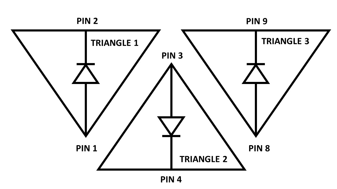
So, if there is no current (if) I activate pin2 as high and pin1 as low. If there is current, it means it is team 2. If there is no current at all, there is no triangle and I will get a 0.
The code was programmed to control 3 possible holes (for 3 triangles) connected to my board:
int triangulos[] = {0, 0, 0};
int pin1Triangulos[] = {1, 3, 8};
int pin2Triangulos[] = {2, 4, 9};
unsigned long previousMillis = 0; // will store last time LED was updated
const long interval = 500; // interval at which to blink (milliseconds)
bool check(int pin1, int pin2) {
pinMode(pin1, INPUT_PULLUP);
pinMode(pin2, OUTPUT);
digitalWrite(pin2, LOW);
if (digitalRead(pin1) == 0) {
return true;
}
else {
return false;
}
}
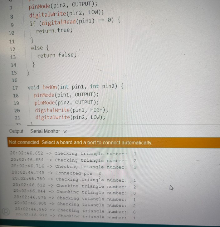
void ledOn(int pin1, int pin2) {
pinMode(pin1, OUTPUT);
pinMode(pin2, OUTPUT);
digitalWrite(pin1, HIGH);
digitalWrite(pin2, LOW);
}
void setup() {
// put your setup code here, to run once:
Serial.begin(9600);
}
void loop() {
for (int i = 0; i < 3; i++) {
if (triangulos[i] == 0) {
if (check(pin1Triangulos[i], pin2Triangulos[i])) {
triangulos[i] = 1;
Serial.print("Connected pos ");
Serial.println(1);
ledOn(pin1Triangulos[i], pin2Triangulos[i]);
}
else if (check(pin2Triangulos[i], pin1Triangulos[i])) {
triangulos[i] = 2;
Serial.print("Connected pos ");
Serial.println(2);
ledOn(pin2Triangulos[i], pin1Triangulos[i]);
}
}
else {
unsigned long currentMillis = millis();
if (currentMillis - previousMillis >= interval) {
// save the last time you blinked the LED
previousMillis = currentMillis;
if (triangulos[i] == 1) {
Serial.println("Cheking 1");
if (!check(pin1Triangulos[i], pin2Triangulos[i])) {
triangulos[i] = 0;
}
else {
ledOn(pin1Triangulos[i], pin2Triangulos[i]);
}
}
else if (triangulos[i] == 2) {
Serial.println("Cheking 2");
if (!check(pin2Triangulos[i], pin1Triangulos[i])) {
triangulos[i] = 0;
}
else {
ledOn(pin2Triangulos[i], pin1Triangulos[i]);
}
}
}
}
}
}
The designed board will be one of the first slaves of the final project. On the final project page you can find the KiCad file of the board and the information about the pins. As you can see, I have 7 free analogue pins and the Tx and Rx to be able to use and program.
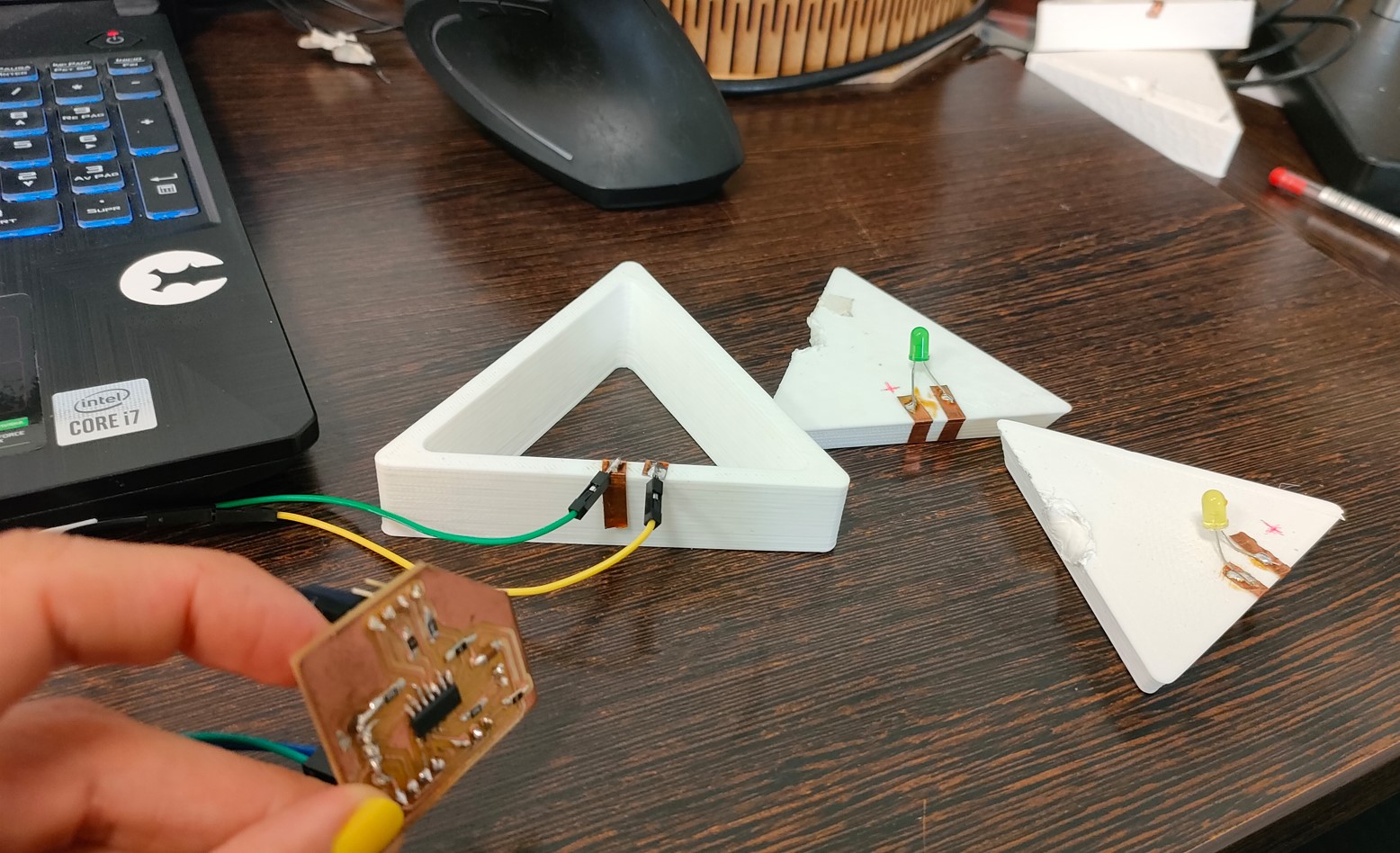
So, we connect pins 1 and 2 to the hole of a structure that mimics the idea of my final project. When you connect the LED in either direction, you can see that it lights up, and you get a 1 or a 2 depending on which way you point the positive pole. This means that if we place the LEDs of one colour different from those of the other colour, I will be able to distinguish which colour is the piece placed through my pins.
This can be reproduced for 3 different slots connected to the 3 pairs of pins indicated in programming.
The operation of this code can be seen below.
Group assigment
This week we probe an input device(s)'s analog and digital signals. The group task can be viewed at Group Assigment page.
Conclusions
There is a wide variety of inputs. Our instructors have shown us many of them and very interesting applications. Many of them are based on variable resistors.
There are many inputs that look alike, and we can make mistakes when connecting or programming them due to confusion. So again, it is very important to look at the data sheet before anything else.