10. Mechanical Design & Machine Design
The echogarden
This week has been very interesting. We are a group of very different people, whose professions are different and at the beginning we were not sure what to develop for this assignment. Therefore, we had to have some meetings in the previous weeks to get ahead, think and discuss ideas. We first thought about our goals for the machine and who could contribute what, as we all have different skills.
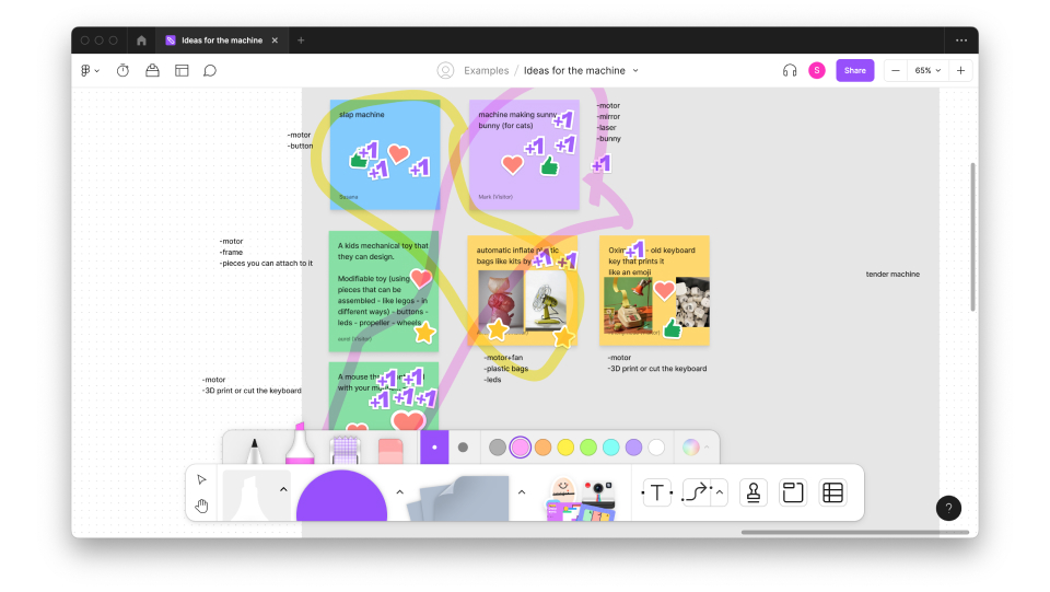
We also thought about what requirements it should meet. Here we decided that we didn't want to make something too big or complex, and we wanted to minimize material consumption. So we had a brainstorming that we narrowed down to 3 main ideas (a bit more explained on the group's website).
After thinking about and settling on just these options, and talking with the instructors, we decided to do a little bit of mixing and matching between various ideas. First we checked everything we had available in the lab or could easily acquire, and decided that we wanted to experiment with the inflatable idea. Since we had to include at least a mechanical part the idea evolved into what we called an "echo garden".
The idea of the "echo garden" is simplified to an air inlet, which passes through a tube and blows, filling the flowers. The idea was that the flowers in the garden are connected to specific sounds, so that when blowing them, the sound produced varies; we intended to create this by using the idea of a plunger flute in our mechanism.
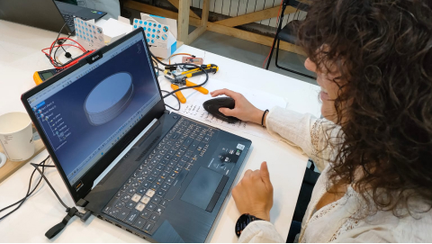
In this sense, we share the tasks in order to work in an equitable manner. My part corresponds to the computer-aided design of the assembly, especially the design and manufacture of the mechanism. All the design was done in Catia V5.
The idea was to design a mechanism that would move the plunger of the "flute". The plunger flute moves in a linear fashion, so the mechanism needed could be quite simple. So, everything was designed in a scaled way to manufacture it and make movement tests without much material consumption and then the larger mechanism would be repeated.
There are different solutions for a simple linear movement. The most basic ones are:
- Worm screw
- Rack and pinion
- Rod Crank Mechanism
The rack and pinion mechanism was chosen because it is one of the simplest, it can be manufactured in 2D (flat parts) and the movement ratio is easy and direct.
A rack and pinion mechanism is a mechanical device with two gears, called "pinion" and "rack", that converts a rotary motion into a straight motion or vice versa. The circular gear called "pinion" meshes with a toothed bar called "rack", so that a rotation applied to the pinion causes the linear displacement of the rack.
The relationship between the pinion rotational speed (N) and the rack linear speed (V) depends on two factors: the number of teeth on the pinion (Z) and the number of teeth per centimeter of the rack (n).
For each complete revolution of the pinion, the rack will move forward by as many teeth as the pinion has. It will therefore move a distance (1) and the speed of the displacement will be (2):
d = z/n (1)
V = N·(z/n) (2)
If the pinion rotation speed (N) is given in revolutions per minute (rpm), the linear speed of the rack (V) is given in centimeters per minute (cm/minute).
Based on this, the mechanism was designed with three 30-tooth pinions. The first one was directly rotating with the motor, and the other two were driven by the first one and in turn transfer the movement to the rack, each of them on one side of the rack, to provide stability.
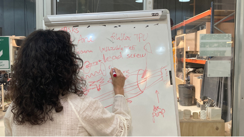
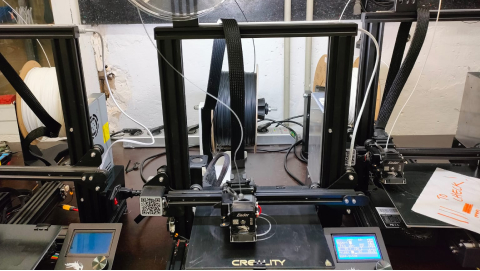
Once the whole mechanism was designed, the parts were printed to see how the mechanism worked. PLA was used as the material, except for a rubber that adapts the plunger to the body of the flute, which was printed with TPU (Filaflex).
The flexible part, although it was printed correctly and worked halfway well, has too much contact area with the tube, causing too much friction and making it difficult to move the plunger. Therefore, the model had to be modified.
The pieces were sanded and some of them were glued to see the functionality of the mechanism.
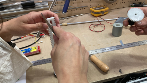
A lot of friction was obtained between the 3D printed parts, although they fit together correctly. Thus, it was thought that perhaps laser cutting of acrylic material would improve the motion transmission of the most important parts of the mechanism (pinions and rack).
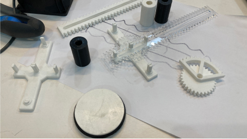
Thus, a prototype of the mechanism to be manufactured was obtained, which worked as shown in the video.
The rack would have the plunger (which in turn would be surrounded by the flexible part so as not to let the air escape) glued to one of its ends. The central pinion would be fitted (by means of a fitting piece) to the stepper motor.
Once I checked that the mechanism worked correctly with the motor, I modified the design to adapt it to the grooved tube we had designed.
After testing the first prototype it was time to 3D print the final parts. Some of the parts were 3D printed with PLA and other parts we used 5mm acrylic and laser cut the parts.
Group assigment
The group assigment can be viewed at Group Assigment page.
Conclusions
The main conclusion of this week is the importance of teamwork. I think we have been able to adapt very well to each other's ideas and also to divide the tasks. In addition, we have made a functional product, although it is not a conventional machine or one that does traditional tasks. In my case, I would never have imagined or proposed to make such a creative machine or product, and I liked that my colleagues were more original and proposed more "crazy" ideas. However, the aesthetics of the final product can be improved, although it is difficult to take into account in only one week of work.
I think we are a good team.