9. Output Devices
Individual assigment
This week I added an output device to a microcontroller board I had previously designed. Then I had to program it to do something.
So, with the board designed and manufactured in the previous weeks, and using some pins that I had left free, I tried to integrate some output.
However, I had not taken into account something important, the ground. Therefore, one of the pins I had used connected to the button I had to disconnect it (cutting the trace with a cutter).
Then, I had to connect the ground to this pin. I had the option of joining them with an external wire or put some solder as I finally did and you can see in the picture, to make it "cleaner".
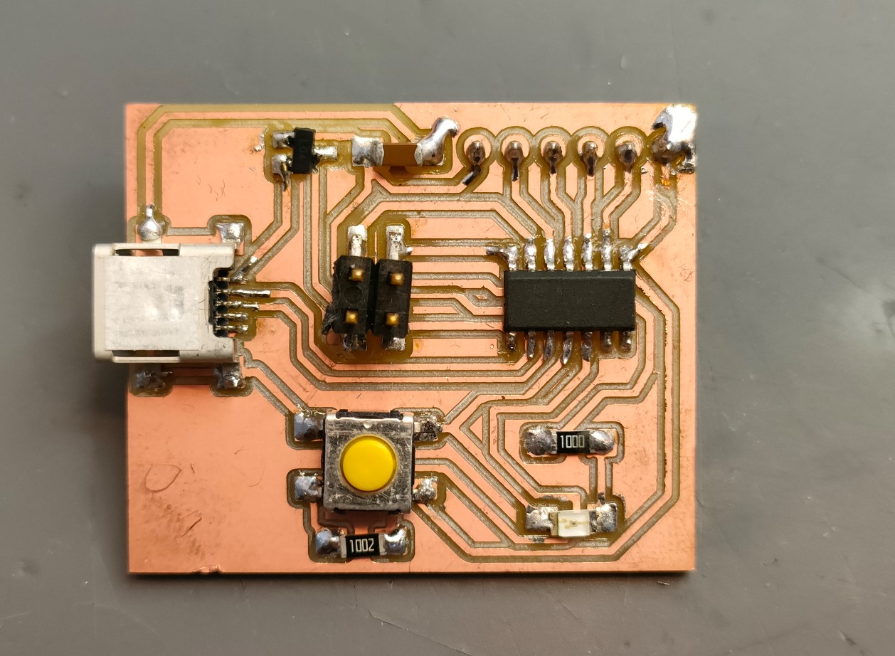
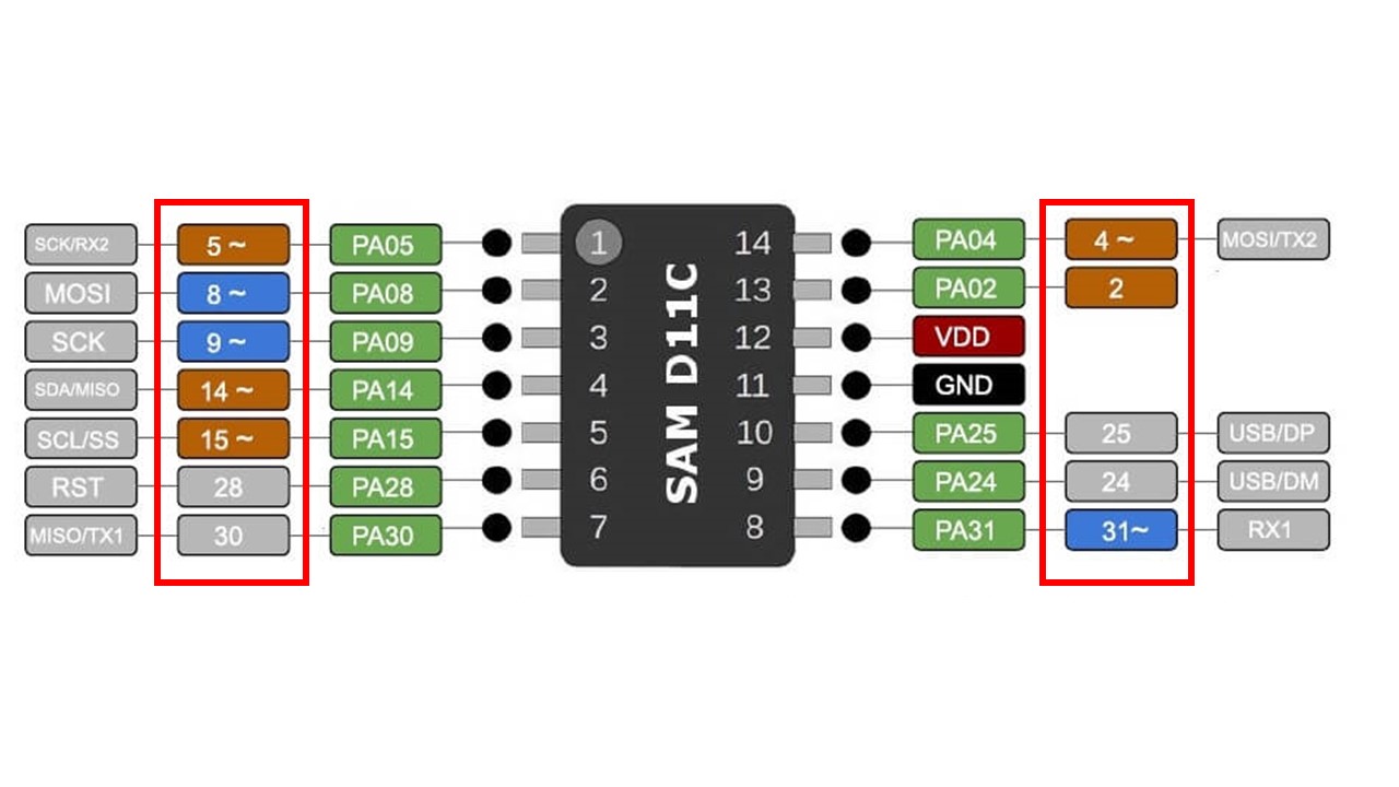
With the ground pins and one of the free pins, I was able to add a vibrator button. Here I had another problem when programming as I always forget the nomenclature of the pins to look at. Including the wrong pins in the programming from arduino, the code does not give error, so I thought that the board was poorly designed. After rechecking the connections and asking my instructors they told me that I should always look at the microcontroller's datasheet.
Also, after trying several times, it seems that the board was deprogrammed, and then I thought I had burned the microcontroller. I just had to reload the bootloader from my terminal.
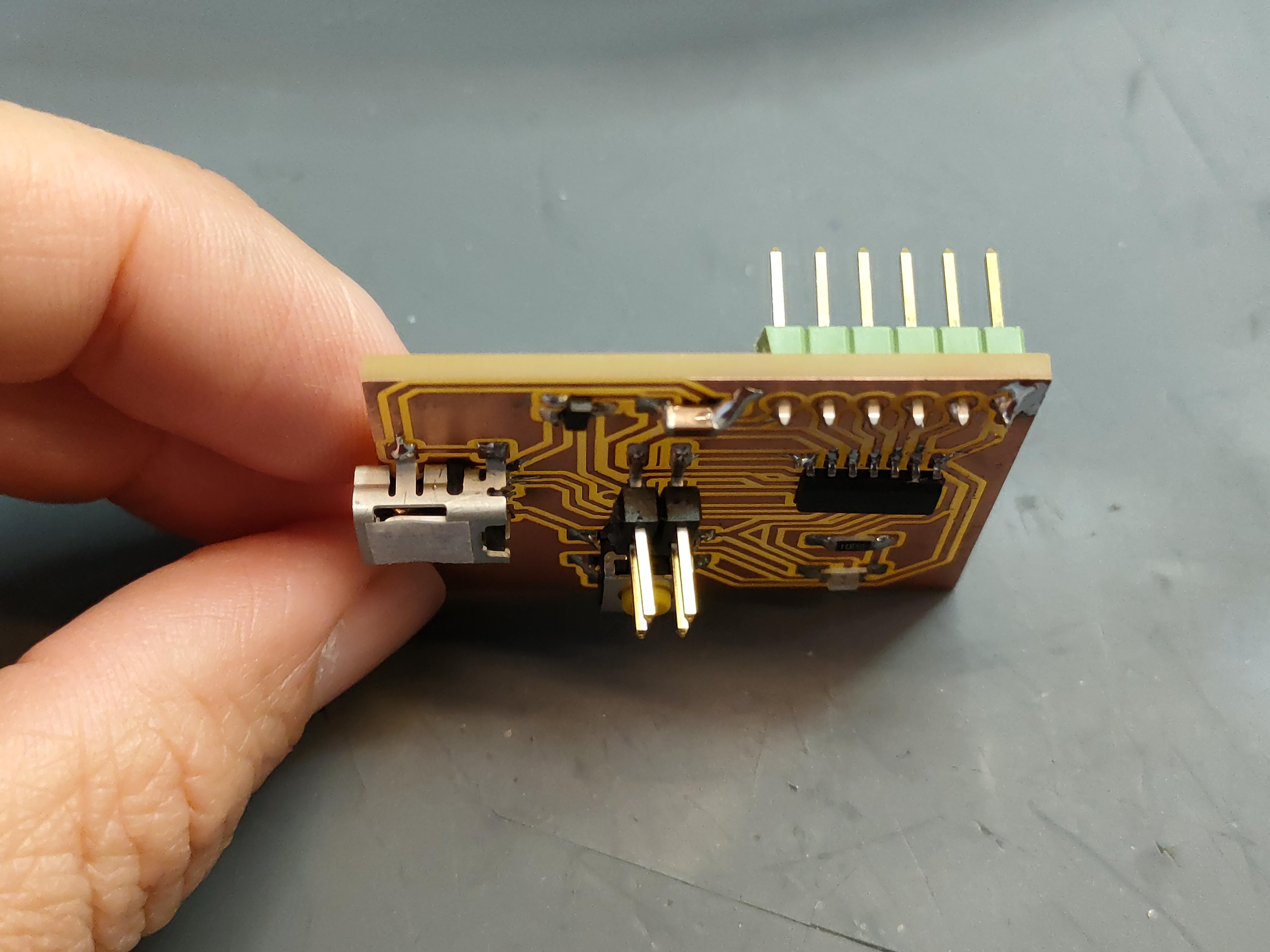
The external pins were soldered to the back of the board since for the front side they could not be soldered unless a gap was left between the board and its support. This could lead to breakage, so it was decided to solder backwards. It is an aspect to keep in mind for another time to put horizontal pins for example.
I was able to load a simple code so that, at the push of a button, the LED would light up and vibrate.
const int buttonPin = 5;
const int ledPin = 8;
const int vibPin = 9;


void setup() {
    pinMode(buttonPin, INPUT);
    digitalWrite(buttonPin, HIGH);
    pinMode(ledPin, OUTPUT);
    pinMode(vibPin, OUTPUT);
}
void loop() {
    int buttonState = digitalRead(buttonPin);
    if (buttonState == LOW) {
        digitalWrite(ledPin, HIGH);
        digitalWrite(vibPin, HIGH);
  } else {
    // turn LED off:
    digitalWrite(ledPin, LOW);
    digitalWrite(vibPin, LOW);
  }
}
Later, I also wanted to try a buzzer. So, using other free pins I programmed a simple code to test it
    #include "pitches.h"

    int melody[] = {
      NOTE_C4, NOTE_G3, NOTE_G3, NOTE_A3, NOTE_G3, NOTE_B3, NOTE_C4
    };

    int noteDurations[] = {
      4, 8, 8, 4, 2, 4, 4
    };

    void loop() {
        for (int thisNote = 0; thisNote < 7; thisNote++) {

        int noteDuration = 1000 / noteDurations[thisNote];
        tone(14, melody[thisNote], noteDuration);

        int pauseBetweenNotes = noteDuration * 1.90;
        delay(pauseBetweenNotes);
              noTone(14);
      }
    }
The melody sounded like in the video below
To operate and control a buzzer or a vibrator button I only need a signal pin and a ground connection. Therefore, any of the free pins on my designed board could be used for this purpose. However, in the code you can see that Pin 9 was used.
In addition, for the devices used as well as for all other devices, a number of considerations must be taken into account:
- Specifications (data sheet). Knowing the nominal or maximum current consumption is essential to know the current requirements and to know how to select the right components.
- Power supply. Make sure that the power supply on my board can supply enough current.
- Protection. It is always advisable to use a resistor in series with many components to limit the current flowing through the circuit.
Finally, and thinking about my possible final work, I wanted to learn how to work with many RGB LEDs. On my board, I only wanted to place 2, but leave the possibility of adding more in the future. To do this, the amperage I had on my power regulator was insufficient, so I had to fabricate an additional board for it.
I then started the PCB design process again with KiCad, including a 3.3V, 1A power regulator. I also added two RGB and included 3 footprints to be able to add more in the future.
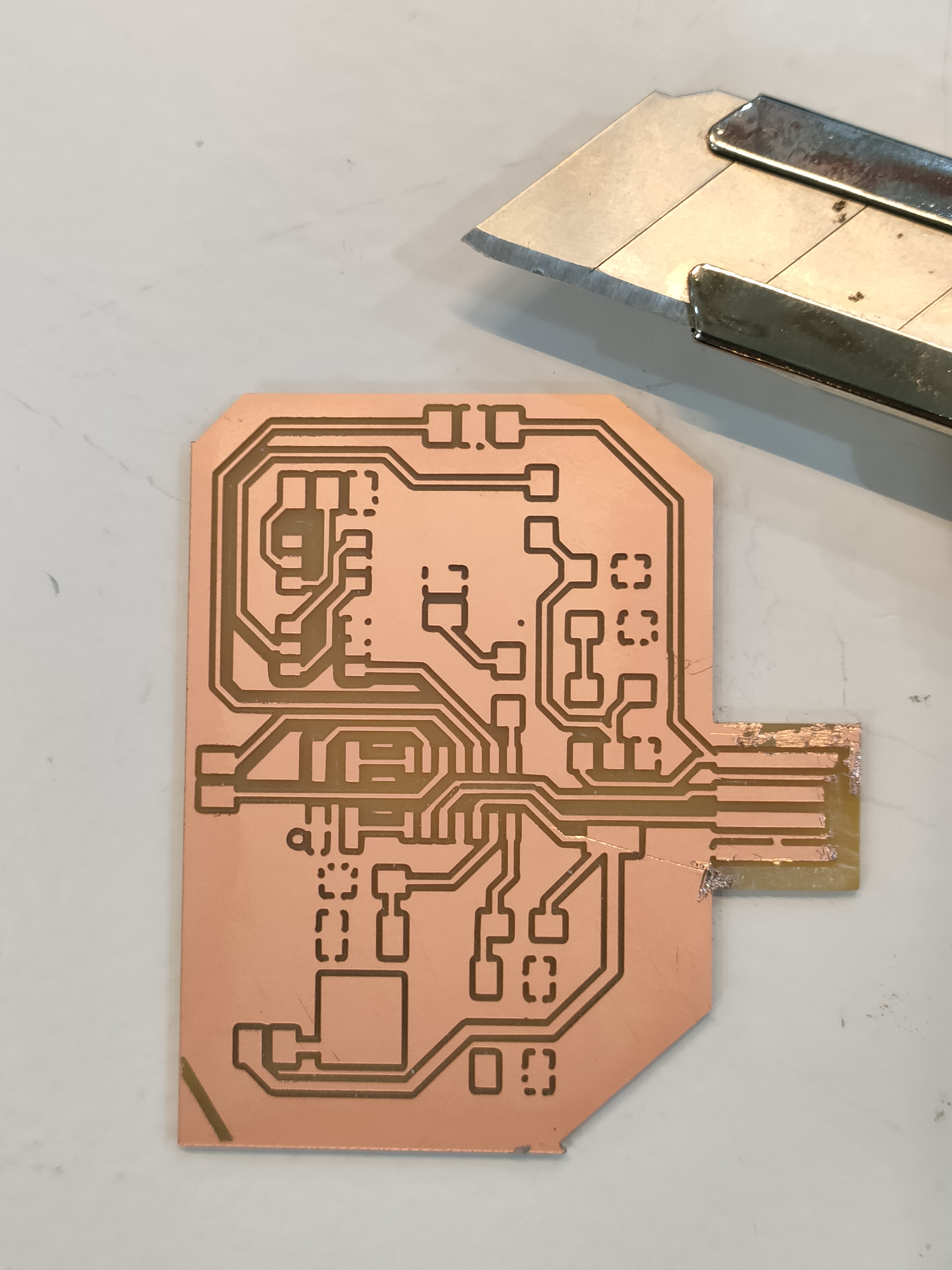
In the manufacture of the board, there were two traces very close together, so the tool did not fit in the middle and left them together. I could have noticed this from Mods. However, and thanks to seeing it before removing it from the machine, I was able to launch the cut of that line keeping my 0 piece.
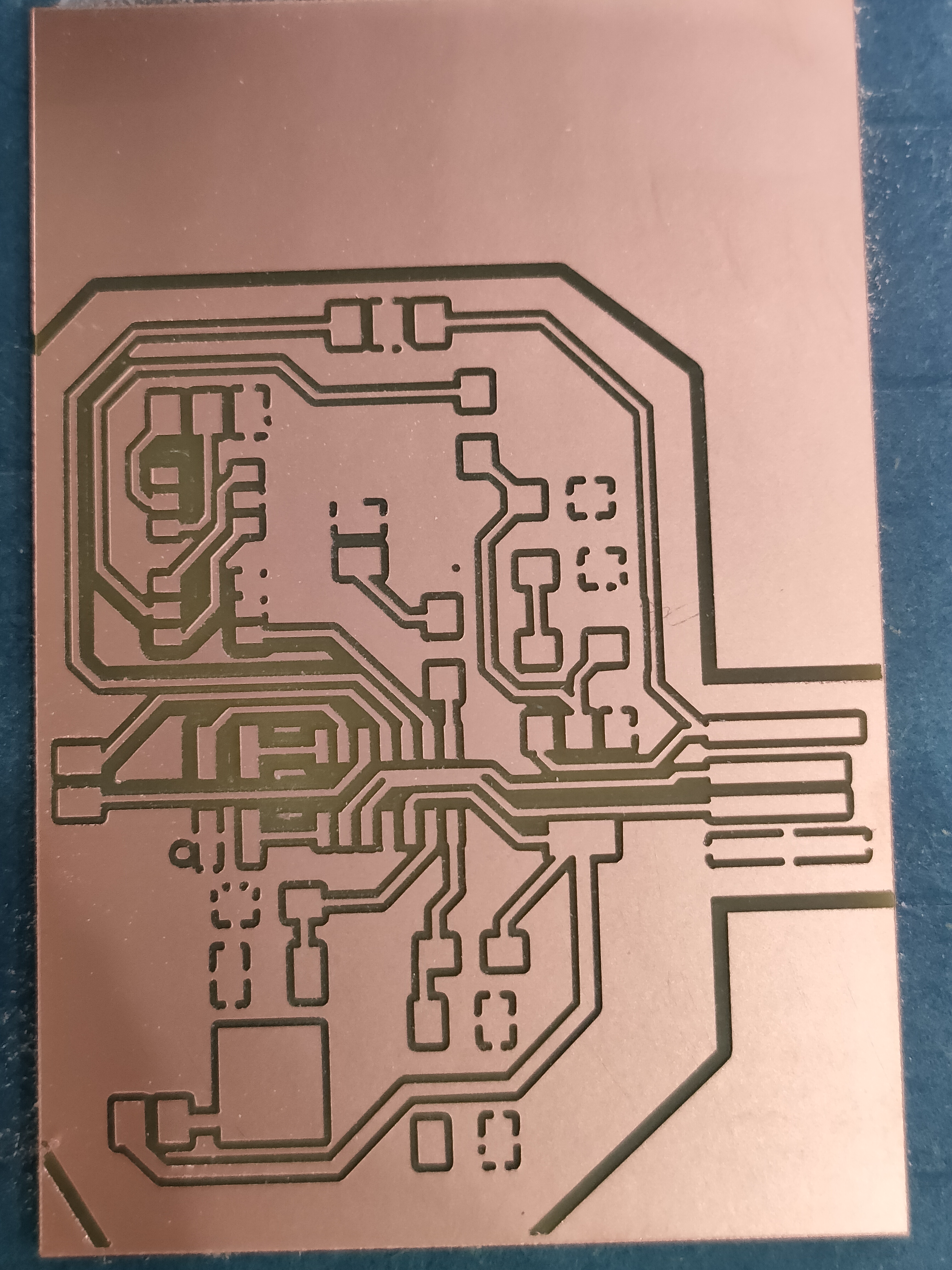
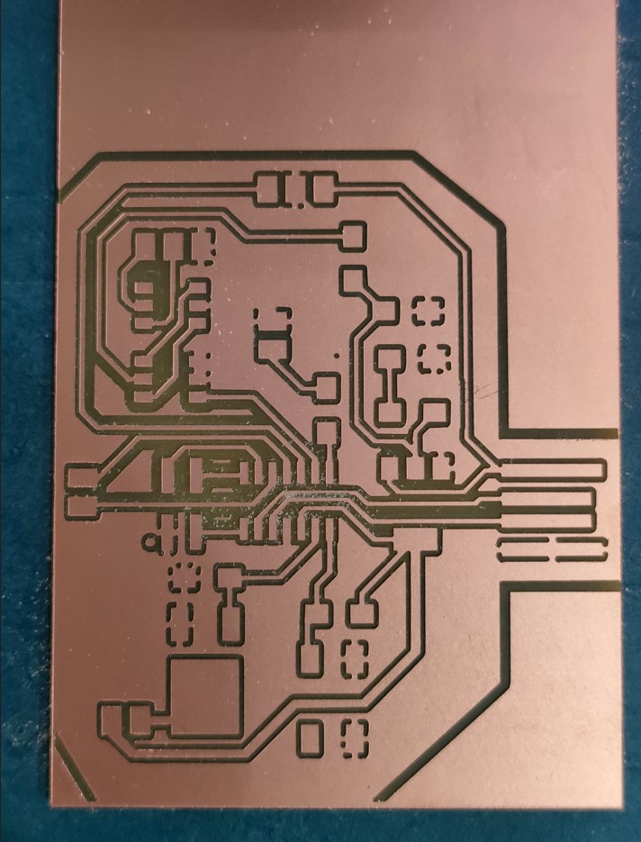
Also, I didn't take into account that I didn't empty the USB area, so it will short-circuit if I plug it in. So, I had to remove the excess copper with the help of a cutter and some patience.
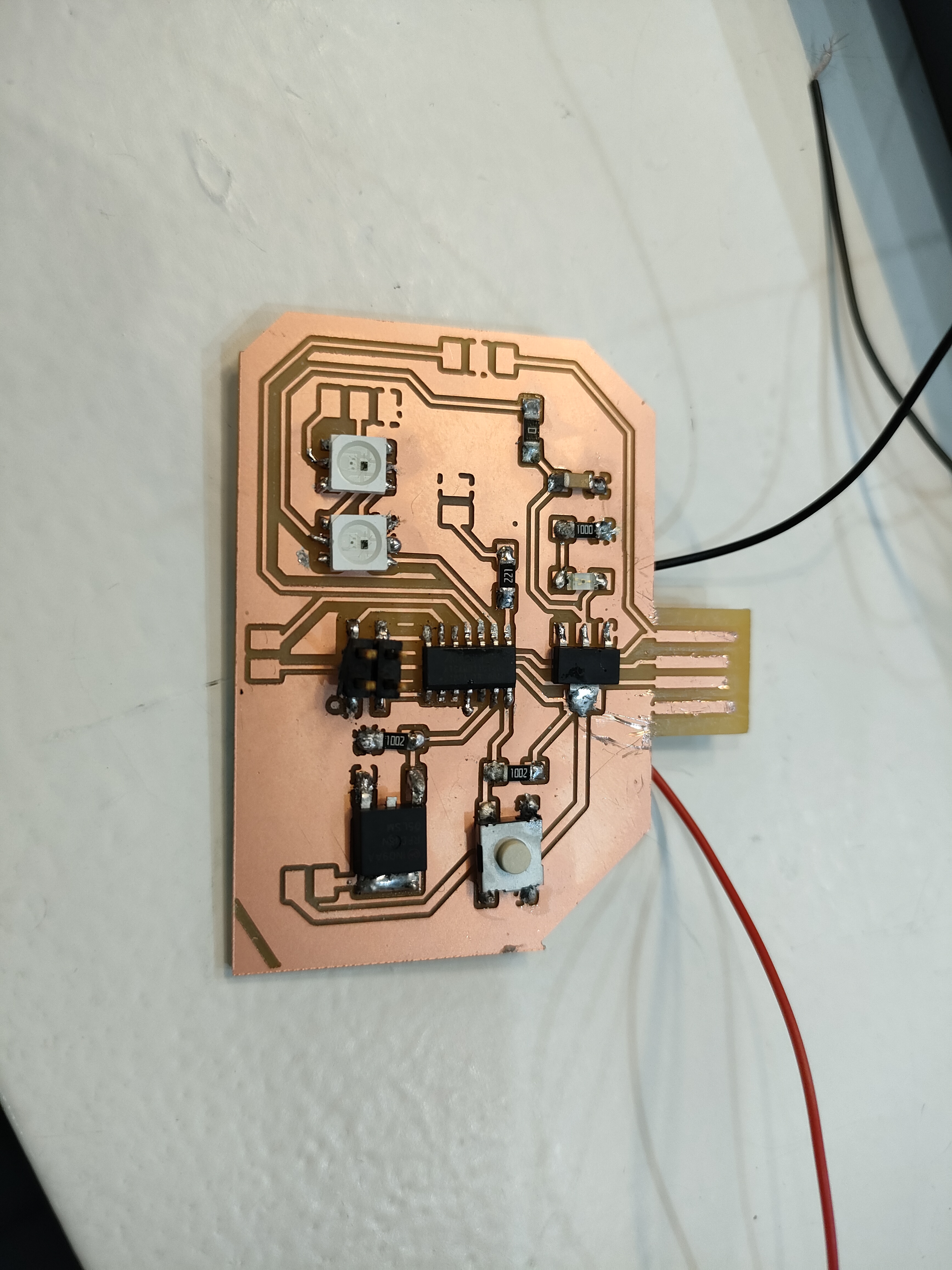
Then I soldered all the components.
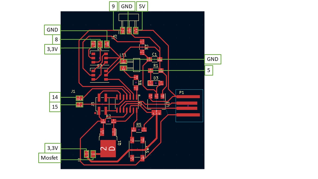
In the schematic of my board included below, we can detect the following free pins or outputs:
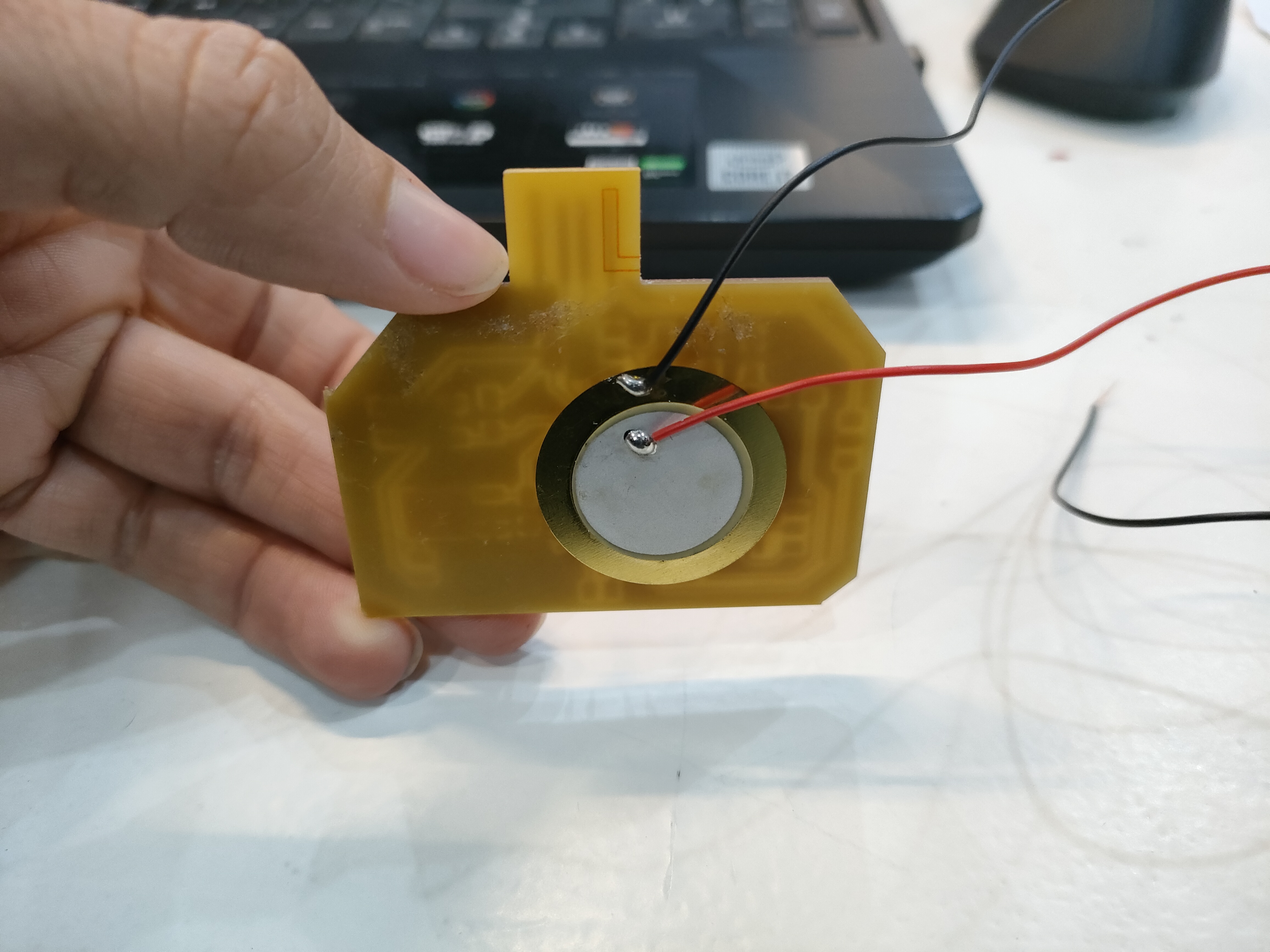
I used a different buzzer. This can be glued to the back of the board (or any area of a desired product). Therefore, it is a more adaptable component to a real product. However, it has a lower maximum volume than the typical buzzer in the electronics kits tested above.
RGBs were also tested. For this, it is necessary to install and include in the code the Adafruit_NeoPixel library. The programmed code for 5 LEDs is included below:
      #include

        #define PIN 8 // data pin
        #define NUMPIXELS 5 // number of pixels that I have
        Adafruit_NeoPixel pixels = Adafruit_NeoPixel(5, 8, NEO_GRB + NEO_KHZ800);

        void setup() {
           pixels.begin();
        }
        uint32_t magenta = pixels.Color(255, 0, 255);
        void loop() {

          uint32_t rojo = pixels.Color(150, 0, 0);
          uint32_t verde = pixels.Color(0, 150, 0);
          uint32_t azul = pixels.Color(0, 0, 150);

          for (int i = 0; i < 5; i++) {

            pixels.setPixelColor(i, rojo);

            pixels.show();

            delay(500);
          }

          for (int i = 0; i < 5; i++) {

            pixels.setPixelColor(i, verde);

            pixels.show();

            delay(500);
          }

          for (int i = 0; i < 5; i++) {

            pixels.setPixelColor(i, azul);

            pixels.show();

            delay(500);

          delay(1000);

          //Now, each LED´s color change
          uint32_t amarillo = pixels.Color(150, 150, 0);
          uint32_t morado = pixels.Color(150, 0, 150);
          uint32_t celeste = pixels.Color(0, 150, 150);

          pixels.setPixelColor(0, rojo);
          pixels.show();
          delay(100);

          pixels.setPixelColor(1, verde);
          pixels.show();
          delay(100);

          pixels.setPixelColor(2, azul);
          pixels.show();
          delay(100);

          pixels.setPixelColor(3, amarillo);
          pixels.show();
          delay(100);

          pixels.setPixelColor(4, morado);
          pixels.show();
          delay(100);

          pixels.setPixelColor(5, celeste);
          pixels.show();
          delay(100);

        }
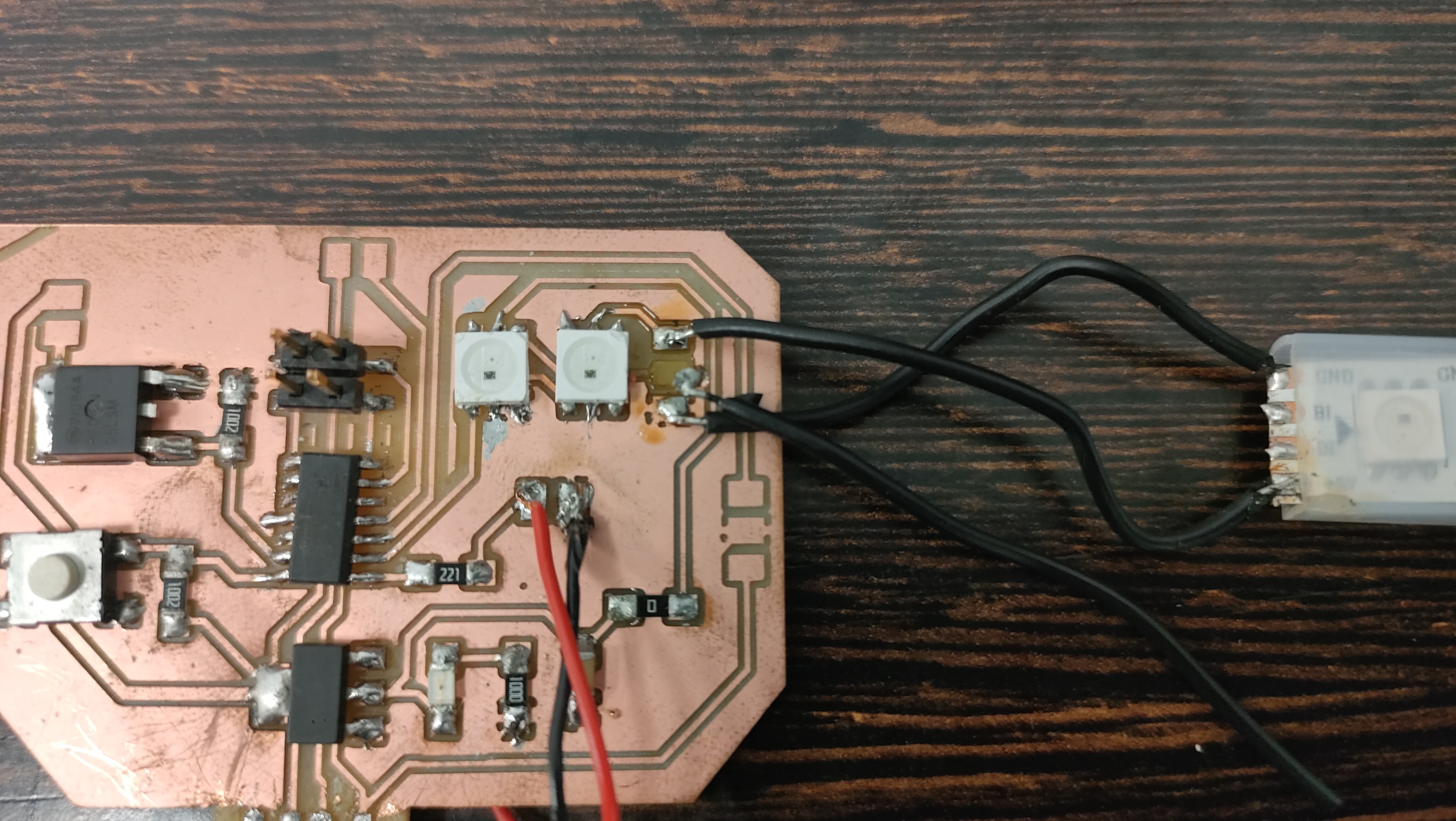
While testing the LEDs, I melted the second one (soldered on the board). This is not a problem, as these LEDs are capable of skipping one. However, there cannot be 2 or more LEDs in a row not working, as they will not be able to pass data.
Next, I tried soldering from the free pins coming out of the LED a small strip of 3. To form the 5 LEDs initially programmed and tested. However, when soldering, I lifted the trace of the output data from the last LED (as can be seen in the photo). Thus, I could not test my board with more LEDs. I decided not to cut another board since I had previously tested the LEDs on a breadboard and the code worked.
Group assigment
The group task can be viewed at Group Assigment page.
Files
The traces file.
The line file.
The outline file.
The KiCad file.
The squematic file.
Conclusions
The main conclusion I draw from this week is that it is always better to test what you want to include on the board through the arduino kit, to avoid errors (this time there have not been many thanks to the reviews of the instructors). Also, be especially careful with the amount of current we need to supply to our components.
Also, be especially careful with the amount of current we need to supply to our components.
In addition, we must check the correct position before soldering. In my case, despite having checked it, with the tweezers when I was soldering it slipped and I finally placed the microcontroller in the wrong position. It took me quite a long time to notice this when the programming was not working, as I was sure I had checked it.
Finally, and as a completely personal consideration, I prefer to include USB output than any other for ease of interpretation on any computer. However, USB is thicker than a conventional board, so we need to make some kind of bracket/tool to attach it properly.