7. Computer controlled machining
Computer Aided Design
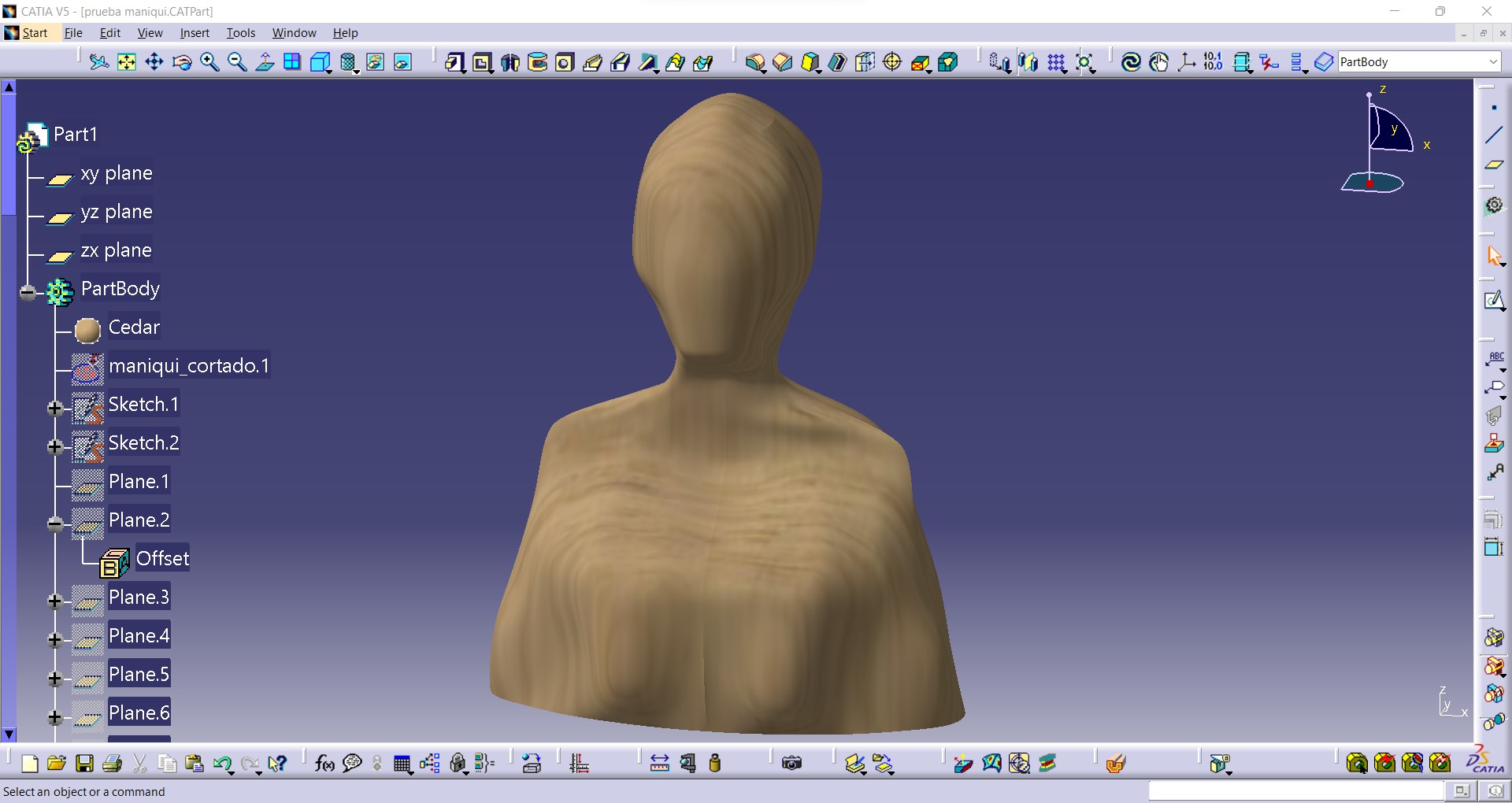
The large piece chosen is a life-size or 1:1 scale mannequin (female bust), which measures approximately 600 (height) x 400 (front width) x 300 (side width) mm.
This part has been designed in Catia, as it is the program I feel most comfortable with (the one I use in my daily work), but the design could be generated in a similar way in any 3D design software.
An image of a mannequin bust has been used and inserted into the program. Based on the contours of this image, some guides have been generated and the multi-section operation has been done from the cross sections to it.
Finally, it has been assigned a material, a type of wood.
Actually the intention of this model is not to make it whole, but to make a laminate so that it is aesthetic, has less weight and we can manufacture it with 2D cutting of wood panels. To do this, we are going to export this model in stl and work with it in the Slicer for Fusion 360 software.
Slicer for Fusion 360
The first thing to do is to define the final size of the model (in mm) and the size of the wood plates available. In this case, the wood plates are limited to the size of the machine (600 x 1000 mm) and have a thickness of 5.5 mm. For this, the boards had to be pre-cut on the laser machine, since larger boards were available.
The final height was defined as 620 mm (the largest dimension of the model), so all measurements were automatically corrected by scaling this dimension.
The next step is to choose the construction technique. In my case, the idea from the beginning was to choose the "interlocked slices", although after several tests I decided to change in the end.
Once the preferred technique has been chosen, it is important to define the slice direction. In the image we can see the difference between the same model with the opposite main direction. The sheets marked in red mean that they cannot be manufactured in the material sheet we have defined or that they cannot be assembled.
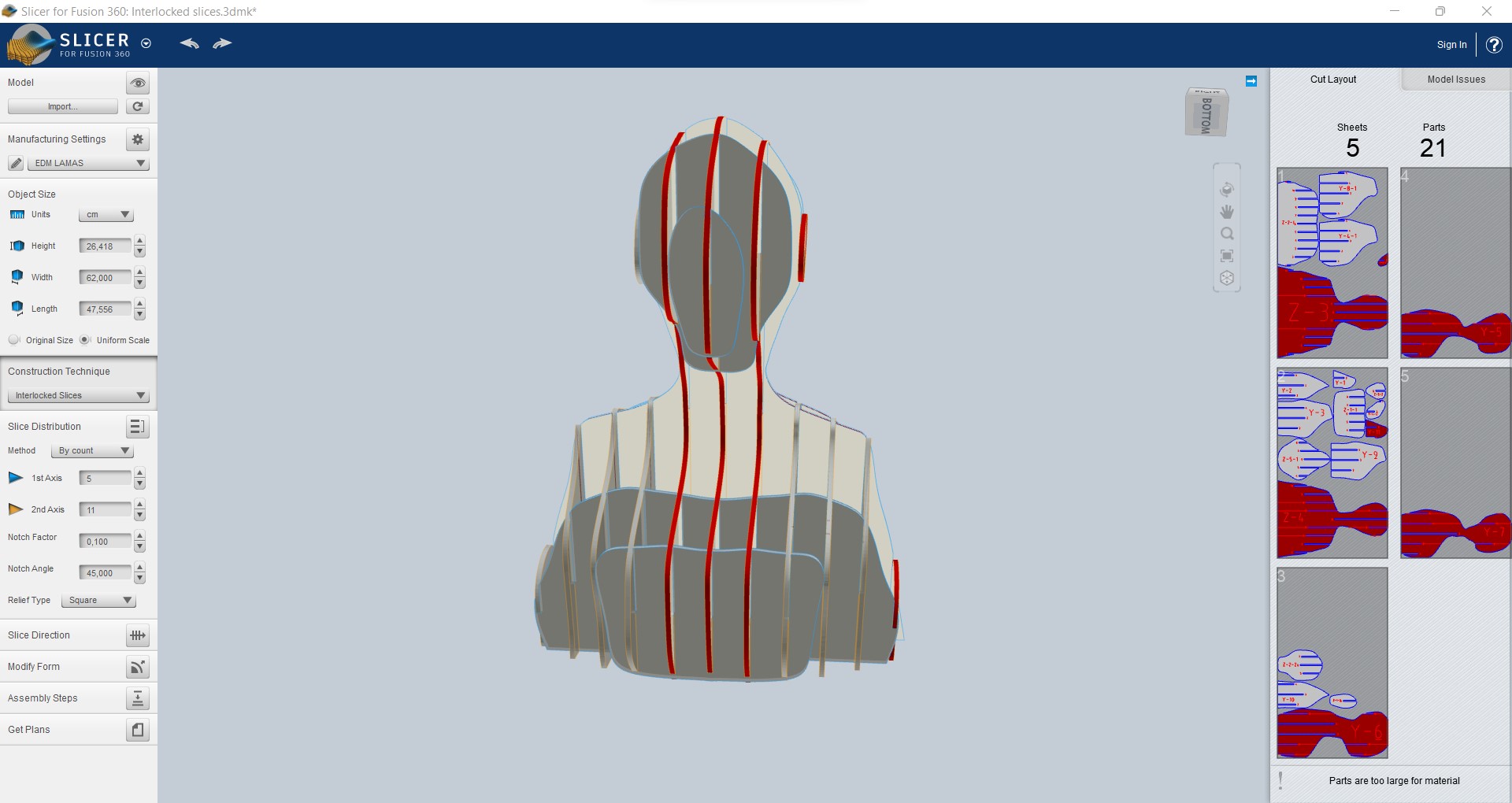
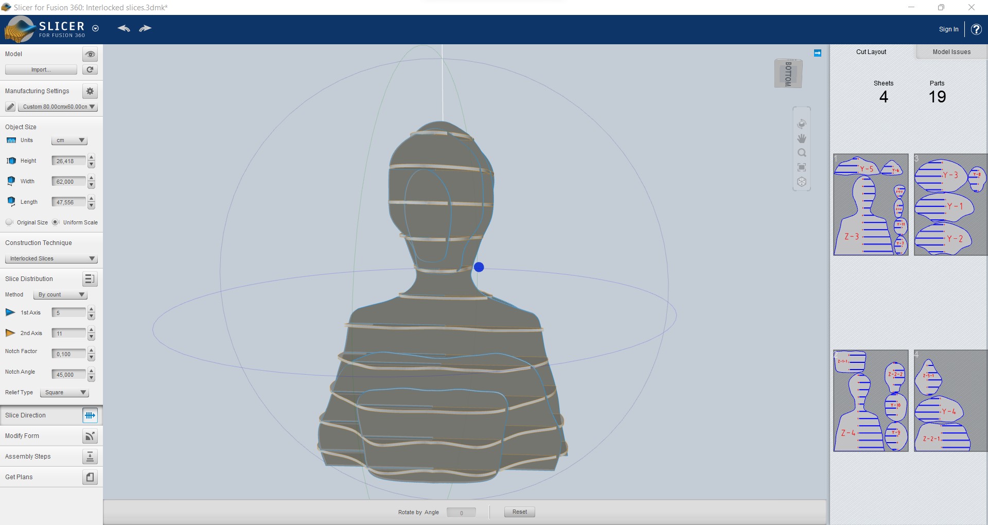
I was able to modify the number of sheets I wanted in each direction, and thus play with the aesthetics and the amount of material available. However, this program does not do very well the nesting, or does not take good advantage of the spaces for the distribution of the pieces, so that later you can make a redistribution in some 2D design software such as Inkscape.
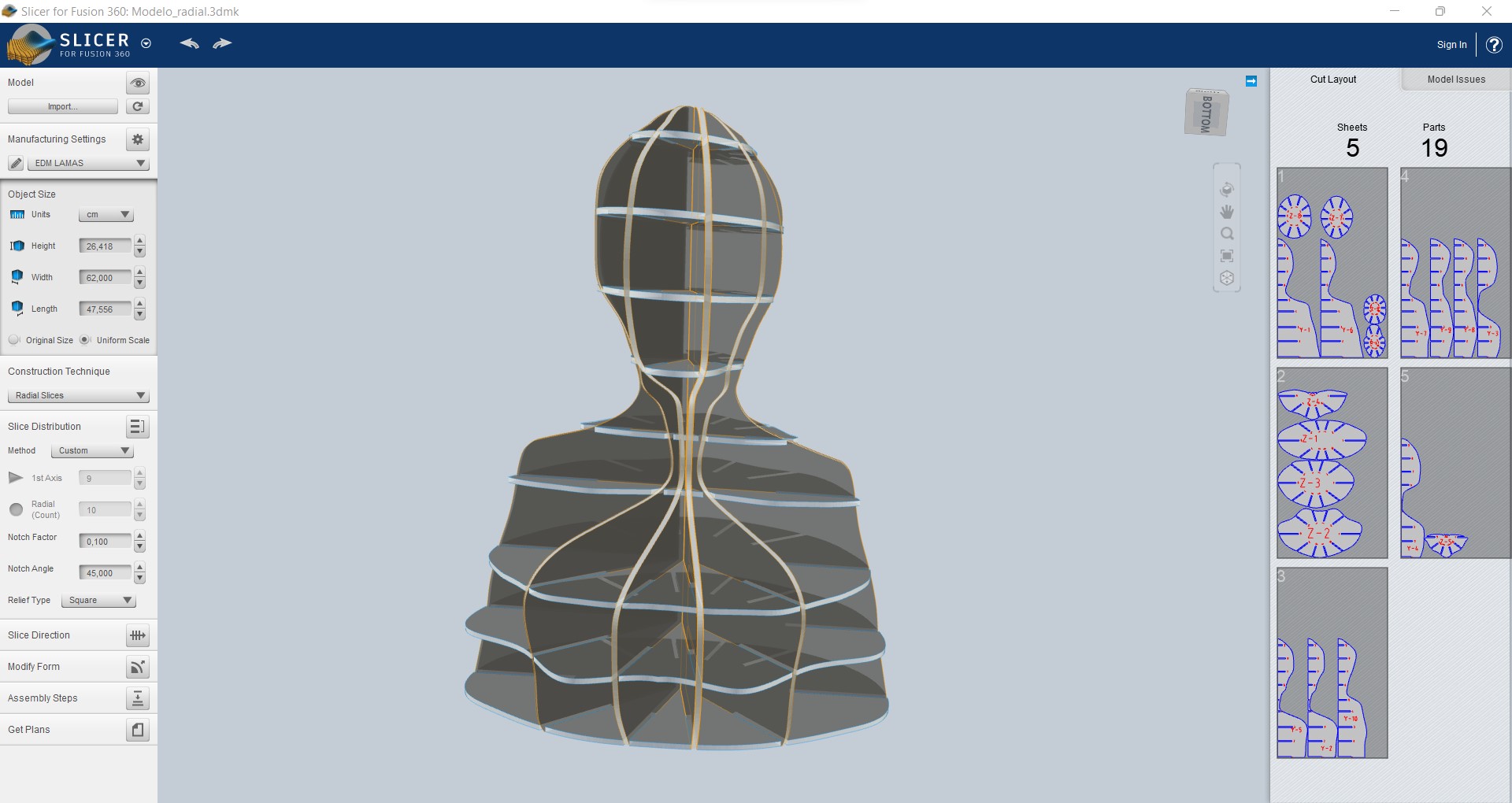
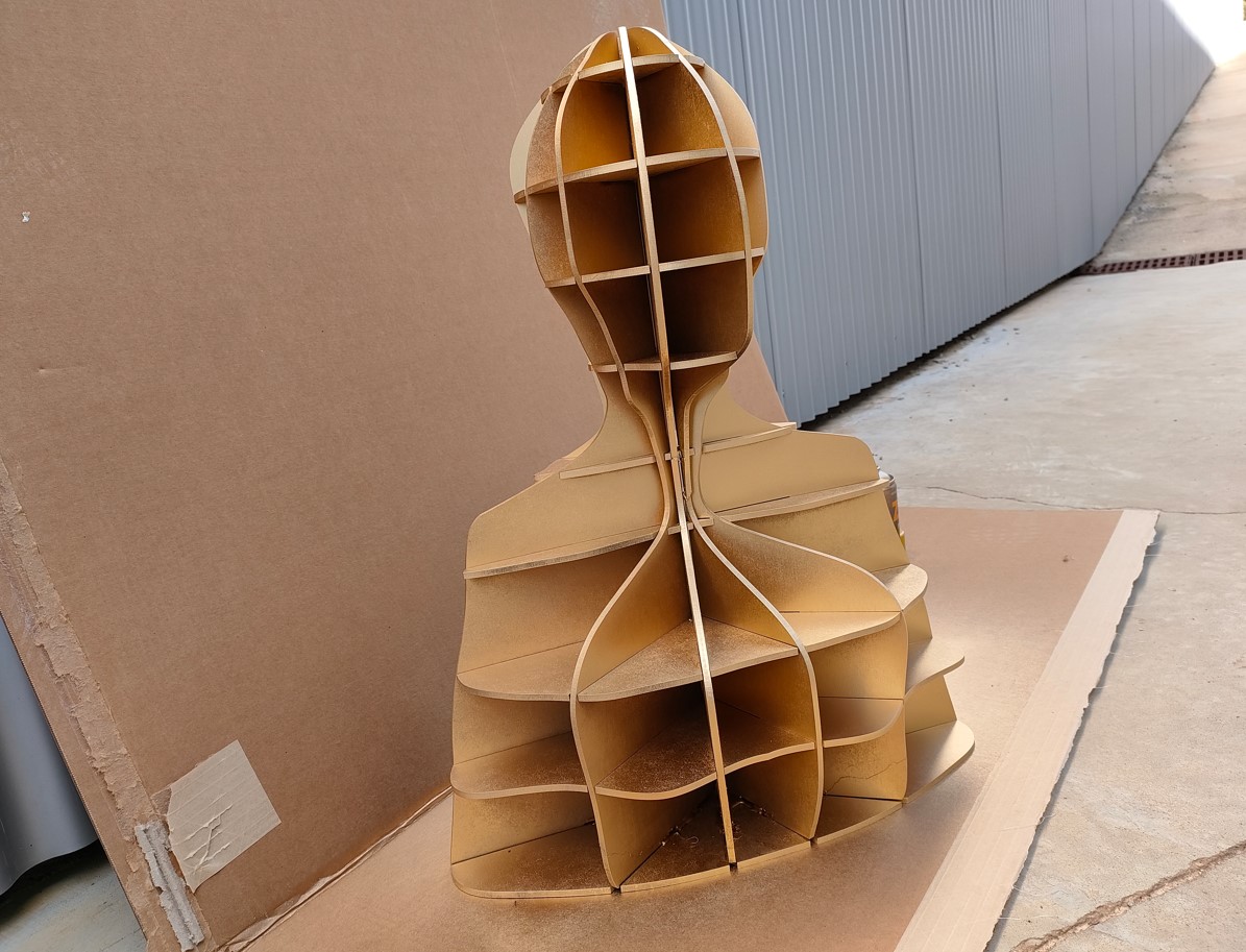
Finally, I opted for a radial design ("radial slices" construction technique) in which one direction of the slices would be horizontal, with the idea that it could serve as a "shelf". The sheets were customized so that the bottom section would be on the surface or floor. This way the model would have the weight on a horizontal plane, instead of having it on the edges of the cross pieces.
Finally, there were 9 pieces in horizontal and 10 in radial position. Some of these geometries had bat-like shapes (the horizontal ones close to the neck of the dummy). Others of the pieces had a very narrow area, which was weak for the assembly. Nevertheless, I liked the model and decided to make it this way.
Computer Aided Manufacturing
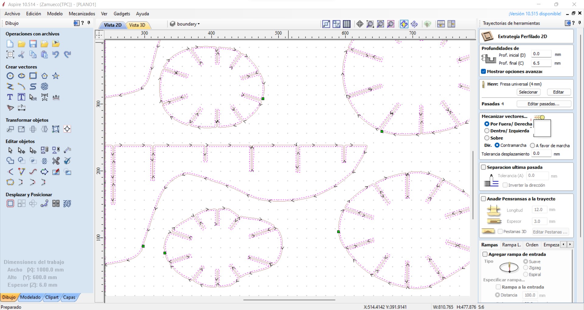
Once we have all the flat paths we want to cut, we import them into the Aspire program in dxf format. In this program, we can also move and modify the geometries (if necessary or if we would like to make better use of the sheet material).
Again we must define the material. In this case, although the plate was 5.5 mm thick, I set a thickness of 6 mm, to ensure a complete cut. It is important to have a sacrificial plate under the material to be cut, so as not to damage the work table.
All cuts were defined with a profiling or straightening technology or path. This means that we will cut only following the drawn trajectories. We can choose from 3 forms of profiling: outside, inside or on top. I chose outside, so that the pieces fit tightly. In reality, they will have some fit with gap, since in the design program I put that the material had 2 tenths of a millimeter more than it really had.
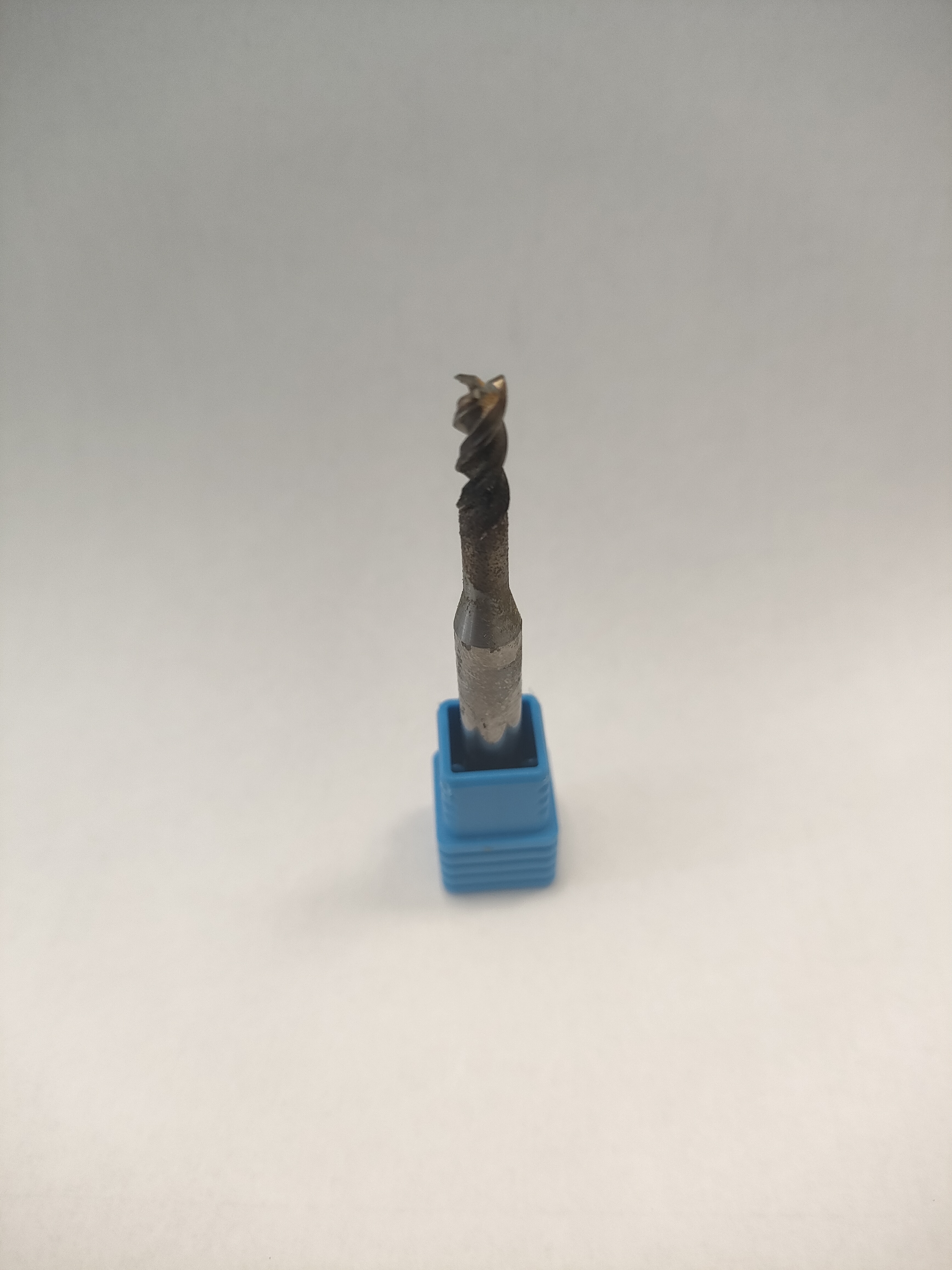
I also had to define the tool and machining parameters. At this point I had several problems and made several tests. The main problem I had is that I did not have a tool for wood, which generally have fewer cutting edges (one or two) and larger evacuation channels.
The first mistake I made was to choose a wooden tool (the only one I had) but with a diameter much larger than the material's plate (12 mm). With this, the voids designed in the model to fit the pieces, are not generated in the program.
Several tests were performed (some results will be shown in the next section) with a 4 mm diameter, 3 cutting edge milling cutter (a milling cutter designed for metal machining).
The manufacturing parameters finally used are shown in the following table:
| Parameter | Value |
|---|---|
| Cutting diameter | 4 mm |
| Cutting depth | mm |
| Cutting speed | 16 000 rpm |
| Feed rate | 1 000 mm/min |
Once the tool paths and parameters have been defined, we can see a small simulation in the program, checking that the tool paths do not overlap, and to find out the approximate machining time.
With this tool we found that, to make 3-pass trajectories and with the parameters indicated by the manufacturer, it takes more than an hour for each of the plates required for this element (4 plates in total). This means a lot of machining time. This long time is due to tests that were done faster, where the material burned. Everything seems to indicate that the geometry of the tool is even more important than the manufacturing parameters, since with the wrong milling cutter, and with different parameters, there were hardly any noticeable differences.
In this program we will export the gcode that will have to be postprocessed in the WinPC-NC machine program.
With the manual movement of the axes, we can place the tool in a corner of the sheet to establish the origin coordinates in the X and Y axes. Once there, we can go to any point on the sheet, start the spindle, and slowly lower the tool in the Z axis until it touches the material. Once it touches, I set 0 in the Z-axis, to make sure the material will be cut on the first pass.
Once the origin is set on the axes, the Z-axis is automatically raised by a few mm. Then I could launch my code to start cutting. It is important to know that from the monitor we can readjust the speeds (in percentage) to modify them insitu if we see that the cut is not going as well as we want.
Manufacturing
I am a remote student, and the machine in my FabLab was not available, so I used the prototyping machine in my university's design lab. The machine and tool used are shown in the following image.
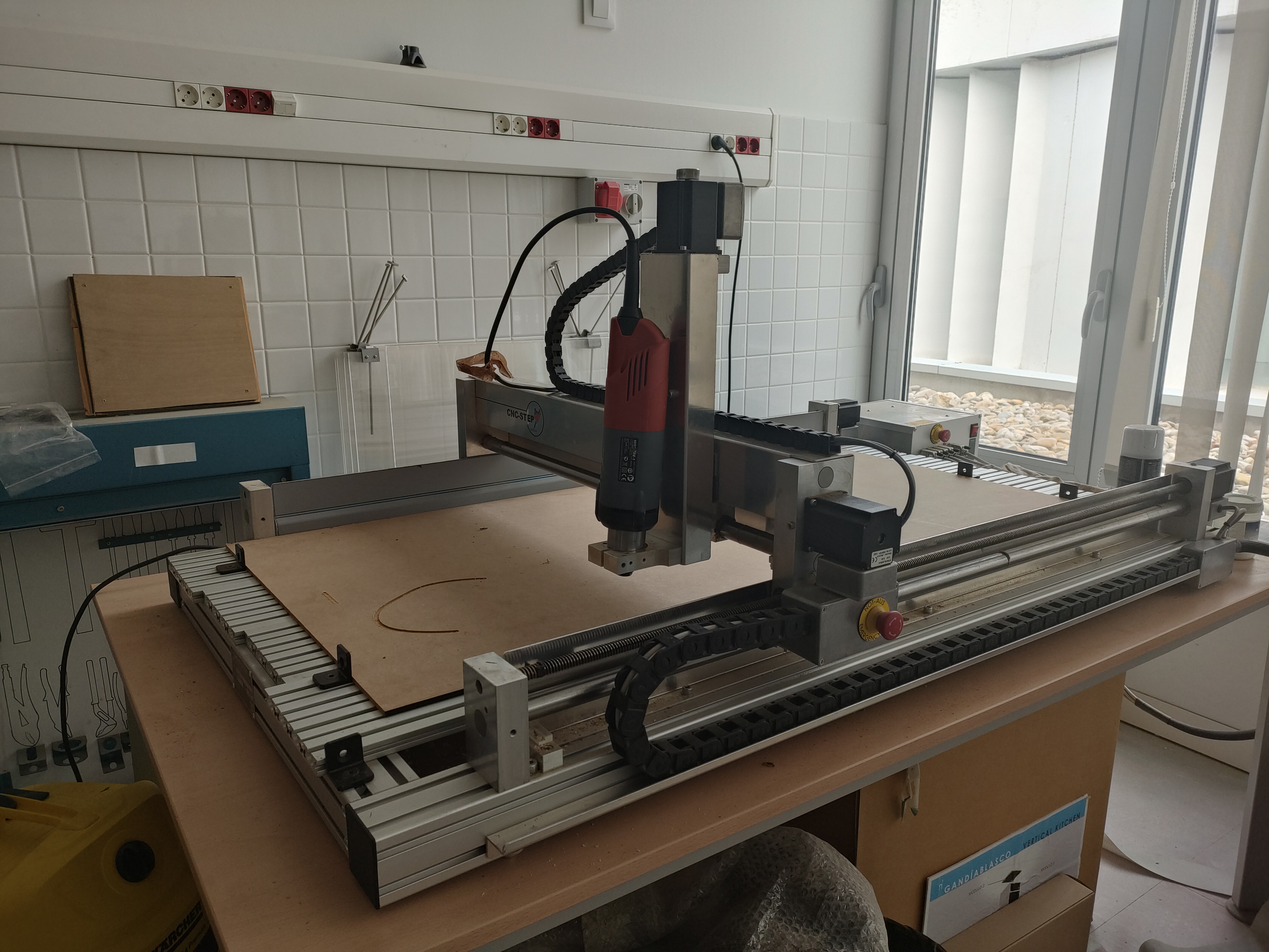
The milling machine used is the High-Z S-1000. As can be seen, it does not have robust mechanics. In addition, as a "machining head" we basically have a manual electric drill. This means that the programmed speed will not be met, although the feed rate will be. Also the tool was not the most suitable, so we had to slow down the speed from the machine software.
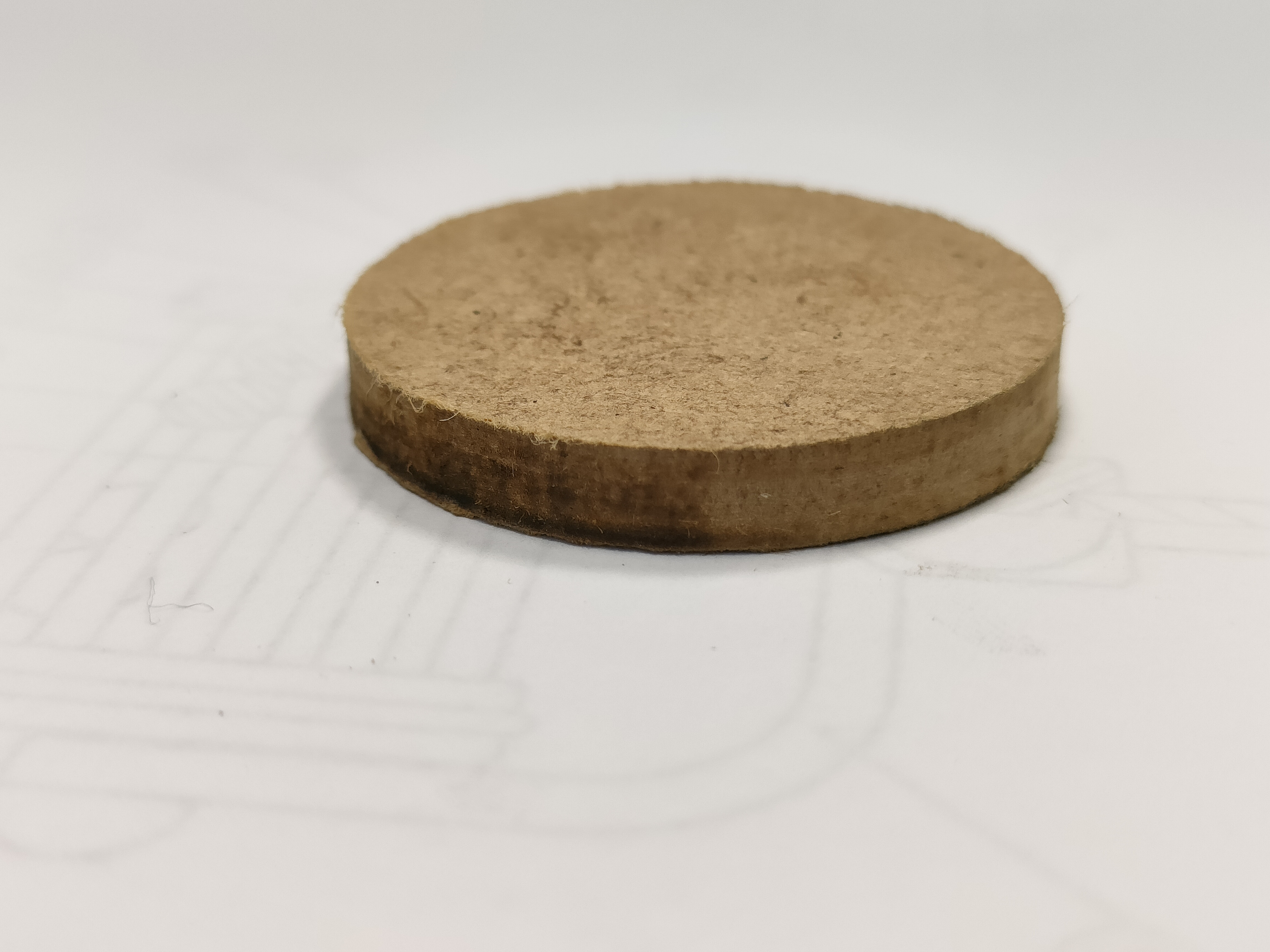
Different tests were carried out, with different manufacturing parameters. In the image we can see how simply a "good" chip evacuation, gives better results than if it is not done. However, this machine does not have a good suction system and a manual vacuum cleaner had to be used directly. The accumulation of swarf causes the temperature to rise, and therefore the surface to burn. In the image on the right we can see the change in the surface with and without suction on the same piece and with the same parameters. We can also see how a very high machining speed (left image, first machining) also affects the results.
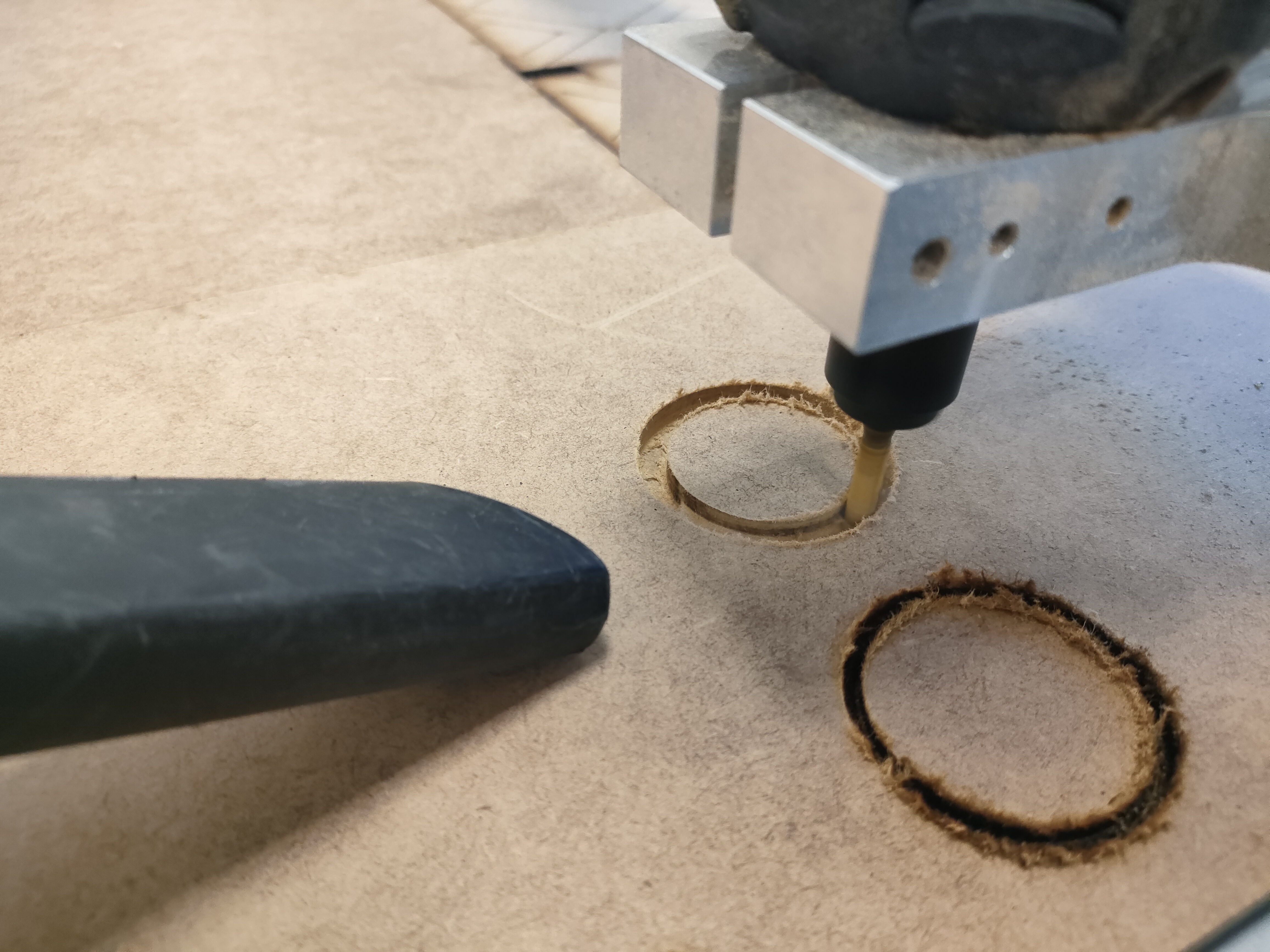
Once the appropriate parameters were achieved, the parts were machined. It should be noted that with the machine software, the parameters indicated in the CAM software are not taken into account. Especially, the cutting speed, since as I mentioned before, it is simply a manual drill placed on the machine carriages. This makes the actual control of the parameters very difficult.
Assembly
To assemble the products, all that was needed was to fit the slots together. They fit perfectly, we just had to be careful where each piece went. Next time, I should mark on the cut itself where each piece goes and name each one of them for easier assembly.
Also, keep in mind that the horizontal pieces should be placed first, with one of the radials, and on these place the other radial pieces.
Once assembled, some glue was put on the lower base of our product, since it was the only one that did not have a total fastening with the rest of the product. For this reason, so that the glue would not be noticed and for aesthetics, I also decided to give it a coat of gold paint.
Safety precautions
In order to use this machinery, it is necessary to use personal protective equipment to ensure our health and safety. In this case, the use of safety boots and earplugs or headbands is compulsory.


It is also highly recommended to wear gloves to avoid cuts from machining burrs and goggles in case of chips.

In addition, in the case of this machine, which does not have an integrated dust extraction system, it is particularly advisable to wear a mask to avoid inhaling particles or dust from the machining process.


Finally, it is necessary to keep an adequate safety distance from the machine when it is machining. This last recommendation has not been particularly implemented due to the need to evacuate swarf and the lack of an integrated cooling or extraction system. For this reason, it was necessary to be relatively close to the tool with a hoover.
Conclusions
As main conclusion of this week is that it is very important to have the right machine and tools to perform a proper cutting process and good qualities. In the case of the machine used I have not had a control of the process parameters, since the spindle speed is controlled by numbers from 1-10 and can not be controlled from the machining software.
On the other hand, the software used Aspire, is a very intuitive software with many possibilities. However, it is not a free software although it is not expensive. In our Fab we have a more suitable machine, which makes the positioning and 0 in Z automatically, more accurate and in which you can better control the parameters. I have no doubt that on any other occasion I will have better results machining this or other materials. Nevertheless, I am happy with the result of the model and with having learned how to use a new CNC machine.
Files
The draws in dxf format.