5. 3D Scanning and printing
This week we have been working with 3D printing and scanning.
In my case, I had some experience with different printers and scanners. However, I preferred to dig a little deeper to find a simple and intuitive software to apply lattice structures to parts with the intention of printing them.
I have used two printing technologies for the individual and group tasks and several methods of point acquisition or 3D scanners.
Group Assigment
In the group assigment we have learned about the existing additive manufacturing technologies. In particular, we mainly used fused deposition modeling (FDM) and stereolithography (SLA).
In particular, we learned the necessary steps to carry out a correct printing. We also learned the main parameters and how they affect the defectology of the parts and the limitations of the process.
My specific task (being a remote student) was to compare the same part printed in Fab Lab Barcelona with the one I did in my lab. I made it by the two techniques mentioned FDM and SLA. For more information visit the group page.
Individual Assigment
3D object design
For the design of a part to be 3D printed I thought of something related to the Final Work. For the dome of the final work I want to make something like a truncated icosahedron. However, this polyhedron could be made by almost any method.
Therefore, it was thought to apply some of the advantages of additive manufacturing to this same polyhedron, to lighten weights and reduce costs through topological optimization. In this case, I proposed to apply a lattice geometry to the truncated icosahedron, simply with the aim of making it visually attractive and that it cannot be manufactured by other methods.
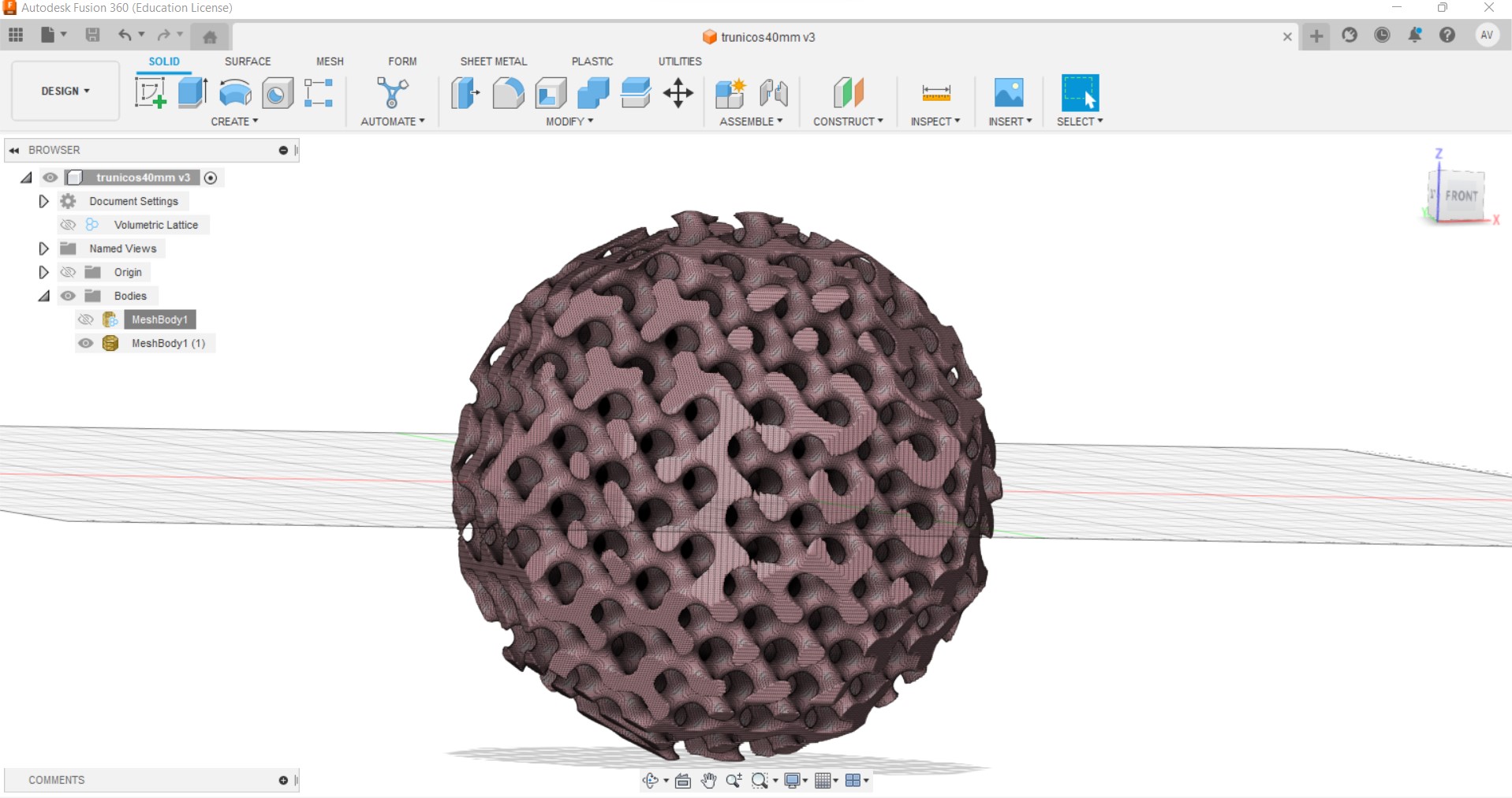
First, the previously designed truncated icosahedron was imported into the Fusion 360 software. To apply the lattice geometries, it is necessary to have the extensions of the product design module enabled. Then, in the program preferences, the "volumetric lattice" option must be enabled in preview features. Once enabled and since the model has been imported in stl from another program, it must be converted to solid by stitching the mesh.
In solid, within the options to modify, there is one that is to convert to volumetric lattice structure.
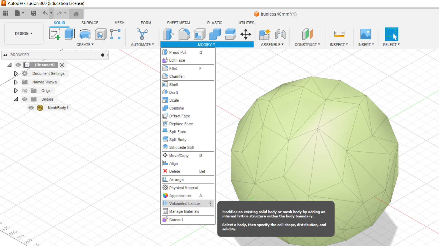
Within lattice, Fusion 360 offers several options of predefined geometries, although it also offers the possibility to generate a unit cell designed by us. We can also decide other parameters such as the unit cell size, the percentage density of the structure, the starting point of the first unit cell, etc.
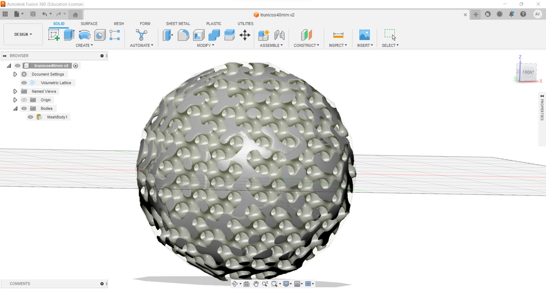
For the design different structures were tested to choose which one I liked the most, considering some of the aspects learned with machine testing and 3D printing defects. Finally, the design I made was made with the parameters collected in the following table:
| Cell shape | Cell size | Proportion | Solidity |
|---|---|---|---|
| Gyroid | 10 mm | Uniform | 35 % |
And the result of the CAD design is presented in the following image:
This design has to be exported in one of the formats supported by the printers. However, in Fusion 360, I must first generate the mesh. Once the mesh is generated, we export it in stl. Although we have learned that the stl format is not the best (since it has no textures or colors), we have chosen this format because it has the least file weight and also because it practically does not affect the technologies used.
The figure shows the previous design made into an optimized and accurate mesh, and exported in stl.
Results of the model 3D
The Fusion 360 program is very intuitive and can be used to generate lattice structures (only manufacturable by additive manufacturing) quickly and easily. However, these structures must first be tested (experimentally or with simulation) if the structure is to support loads.
The choice of my design, although it is not a technically structural part, was due to my interest in lattice structures and the Fusion 360 program, which I did not have time to test during the CAD design week. I am relatively satisfied, since I would like to test the simulation options for this type of structures and see if they resemble the experimental results.
The main problem detected in these designs is the export in stl. The change from one software to another in this format does not maintain the dimensions, which generates a change of scale sometimes not controllable. Therefore, it is advisable to do the whole design process in the same software if you plan to work with stl. Or on the contrary, I recommend using other formats such as obj or 3mf.
3D object manufacturing
The fabrication of the designed object was approached in two technologies: stereolithography (SLA) and fused deposition modeling / fused filament fabrication (FDM/FFF). These technologies require different parameters, times and generate different results that will be discussed below.
The object to be printed showed scale changes in some software modifications, so it was finally given a final volume of 40x40x40 mm.
Fused Deposition Modelling
For the printing of this object, and having tried several materials in the initial tests, PLA (from the company Smartmaterials) was chosen because it is a very easy material to print.
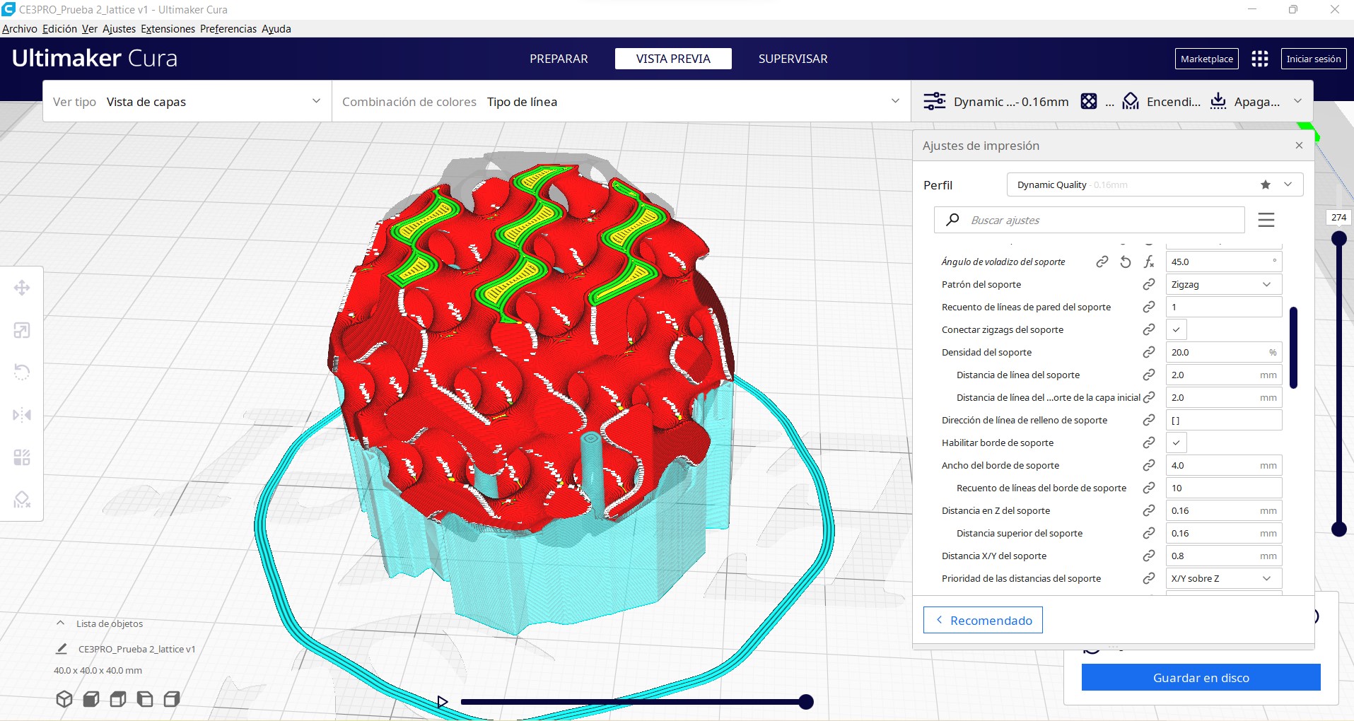
To print the part, the file in stl format was imported into the Cura software. As tests had already been carried out with this material, the main parameters used are shown in the following table:
| Parameter | Value |
|---|---|
| Layer thickness | 0.2 mm |
| Path width | 0.4 mm |
| Infill | 100% (concentric) |
| Temperature | 210ºC |
| Bed temperature | 45ºC (optional) |
| Print speed | 50 mm/s |
| Support | Active at the base |
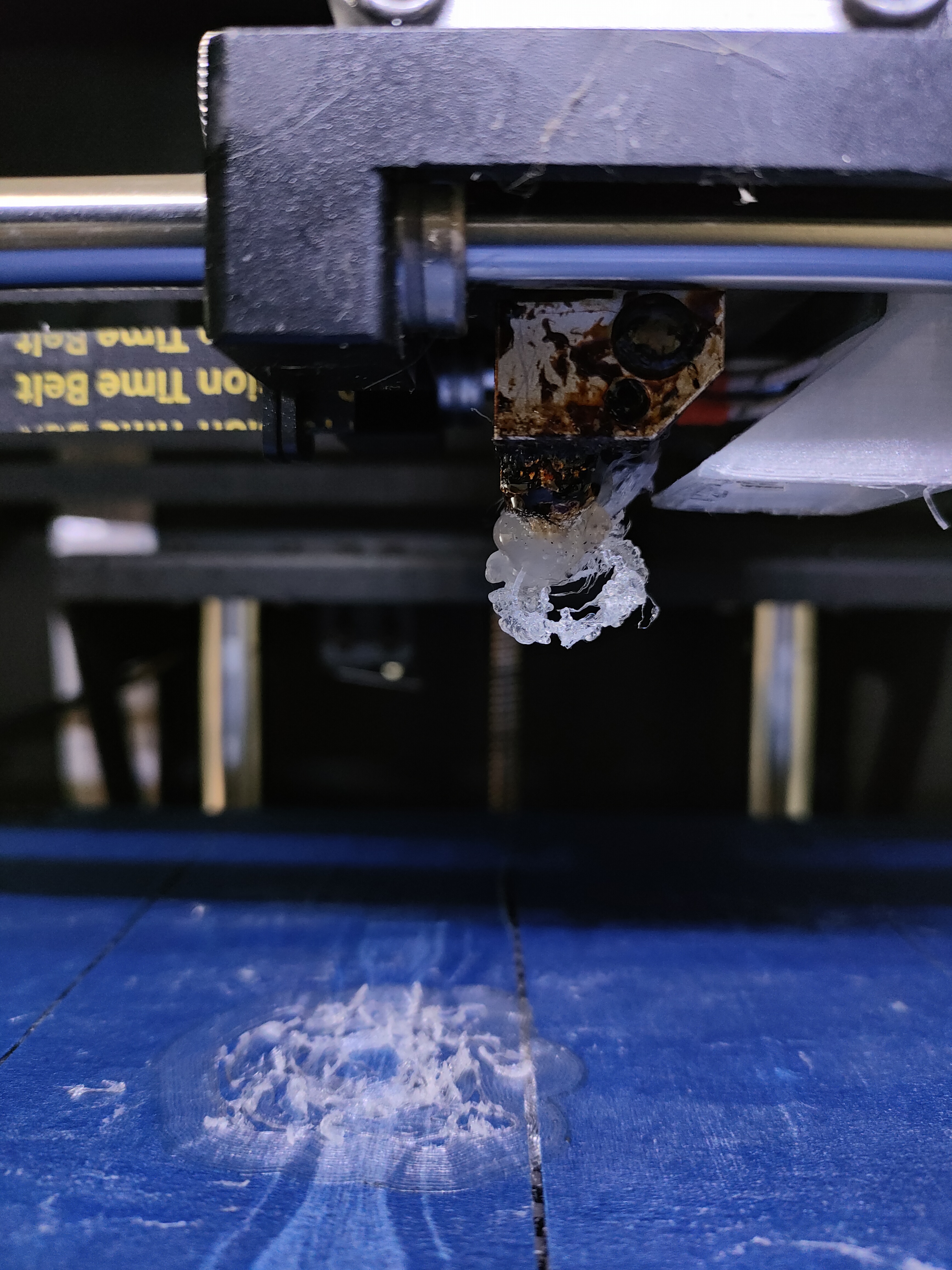
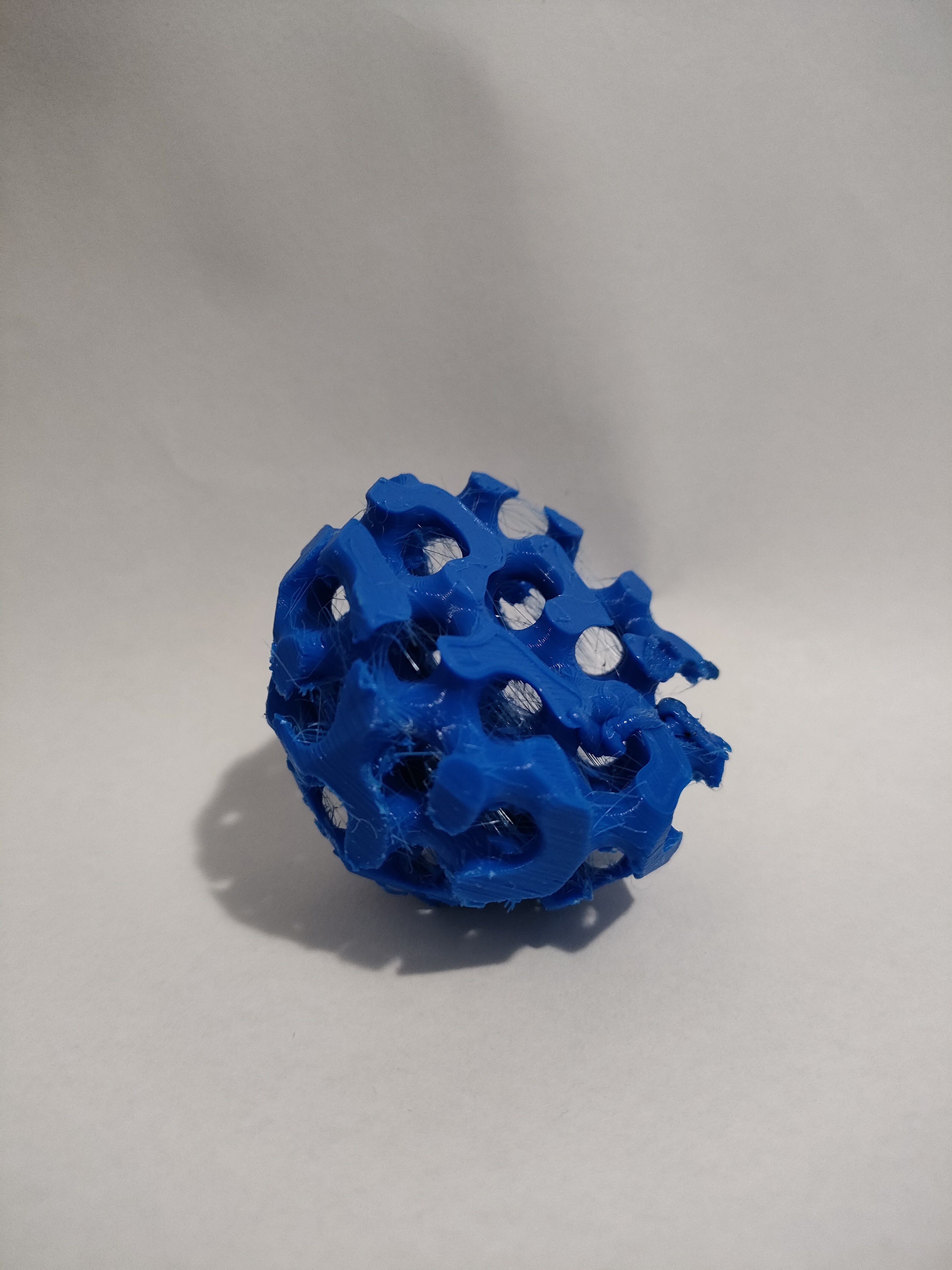
Supports were used on the base to have a better fixation to the platform. This is because in a first test without them, the piece detached from the platform and stuck to the hot end (you can see in the image on the left that first test). In a second test, the material was brittle due to moisture absorption, and broke. This resulted in a vacuum print (no material deposited) since it was about half way through (you can see in the image on the right the uncompleted part).
The Creabot DX printer was used to print the part. The printing time according to the software was approximately 6 hours and 19 minutes, with a material consumption of 56 gr.
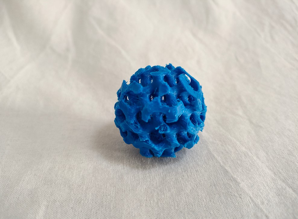
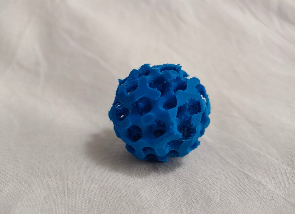
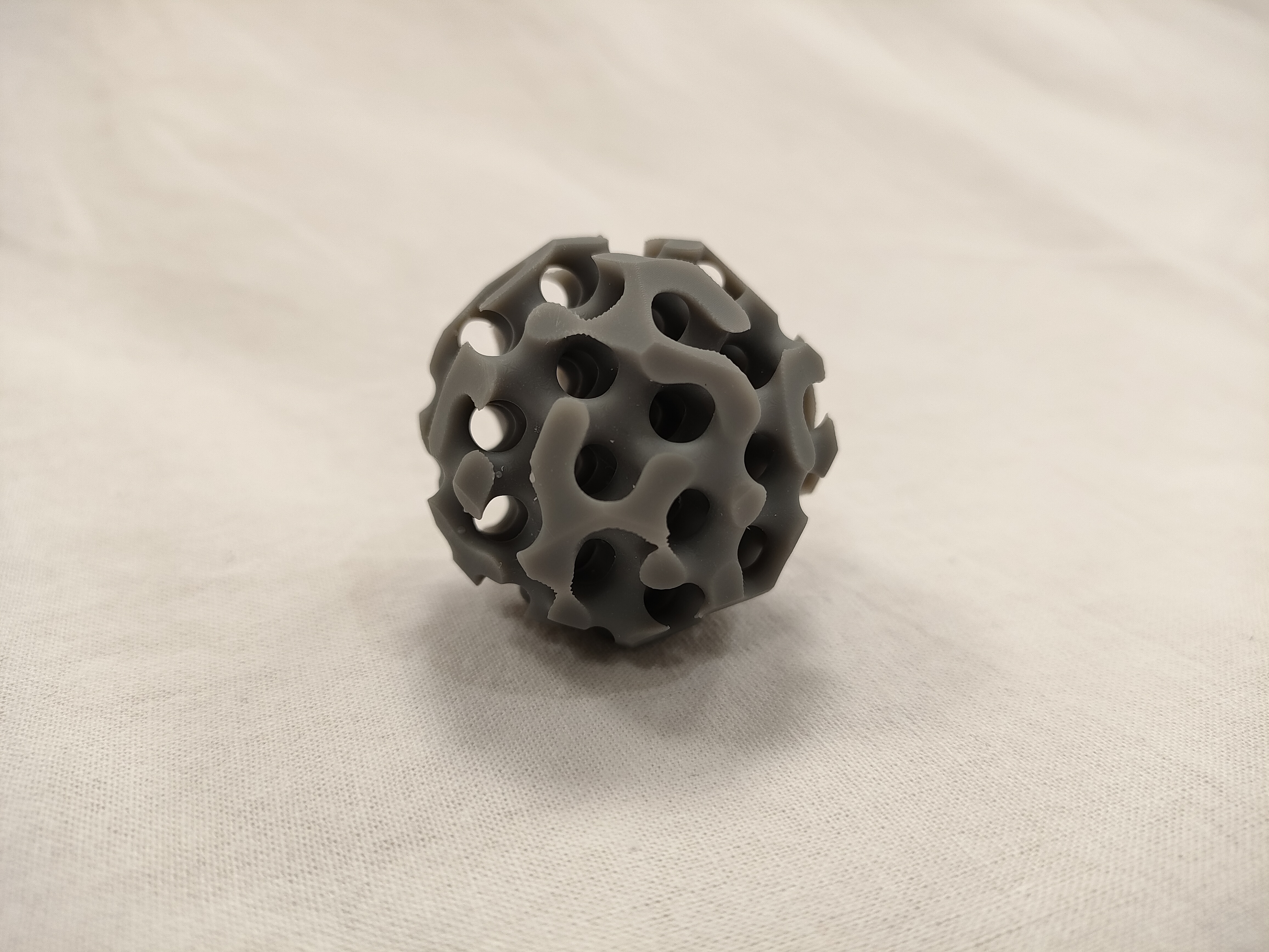
Once the part was printed, the supports were removed and we observed the satisfactory result shown in the following image.
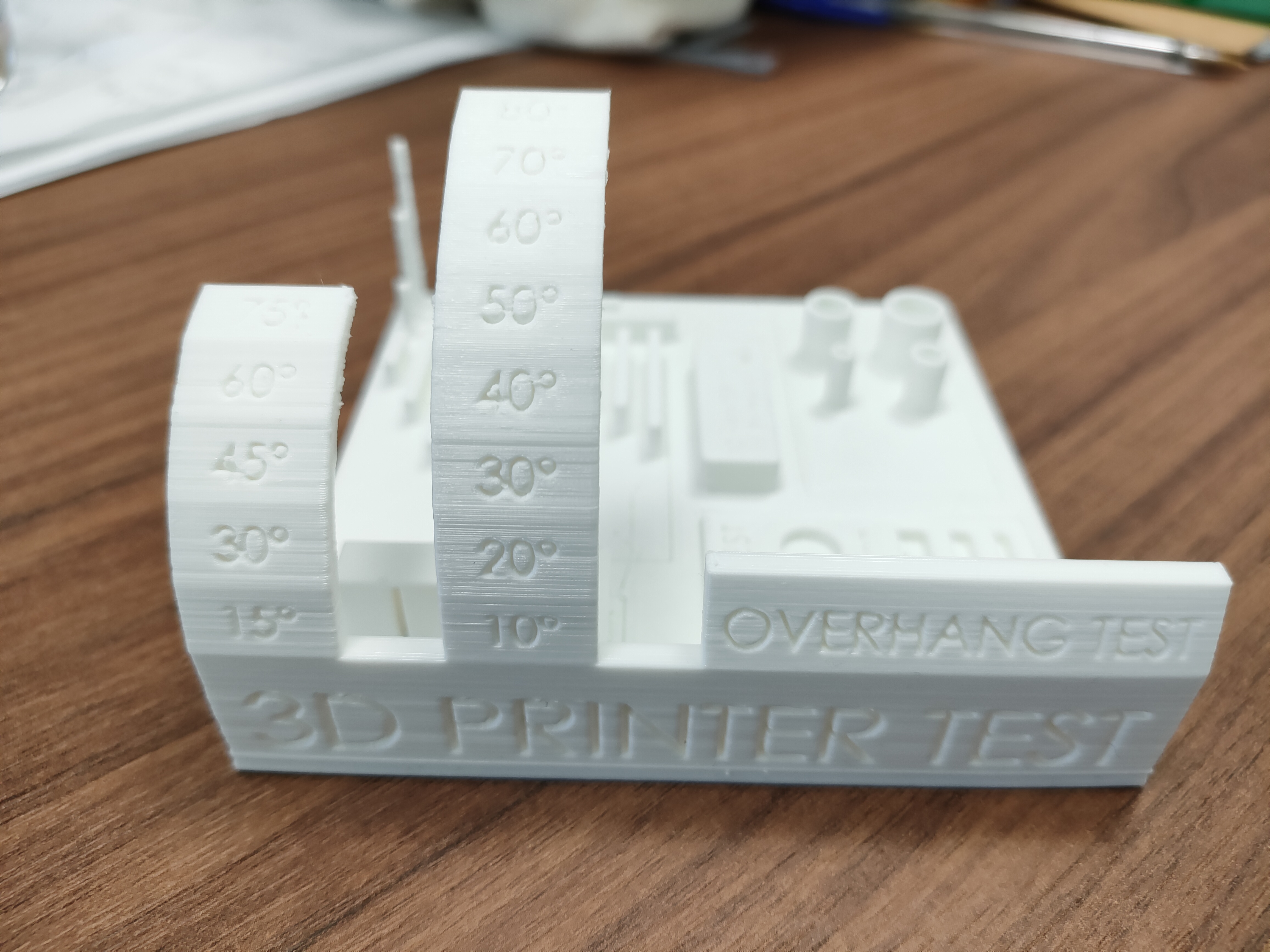
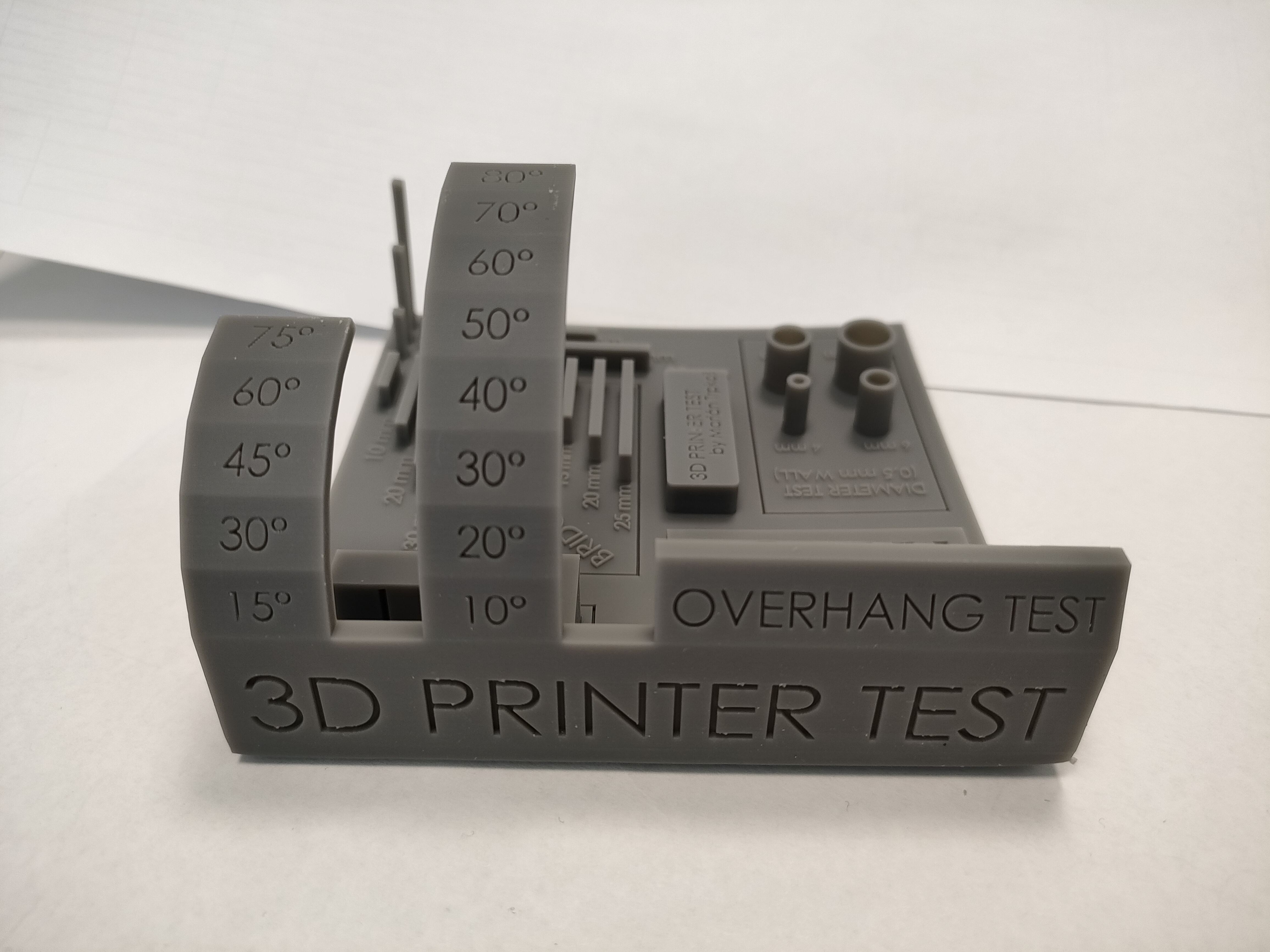
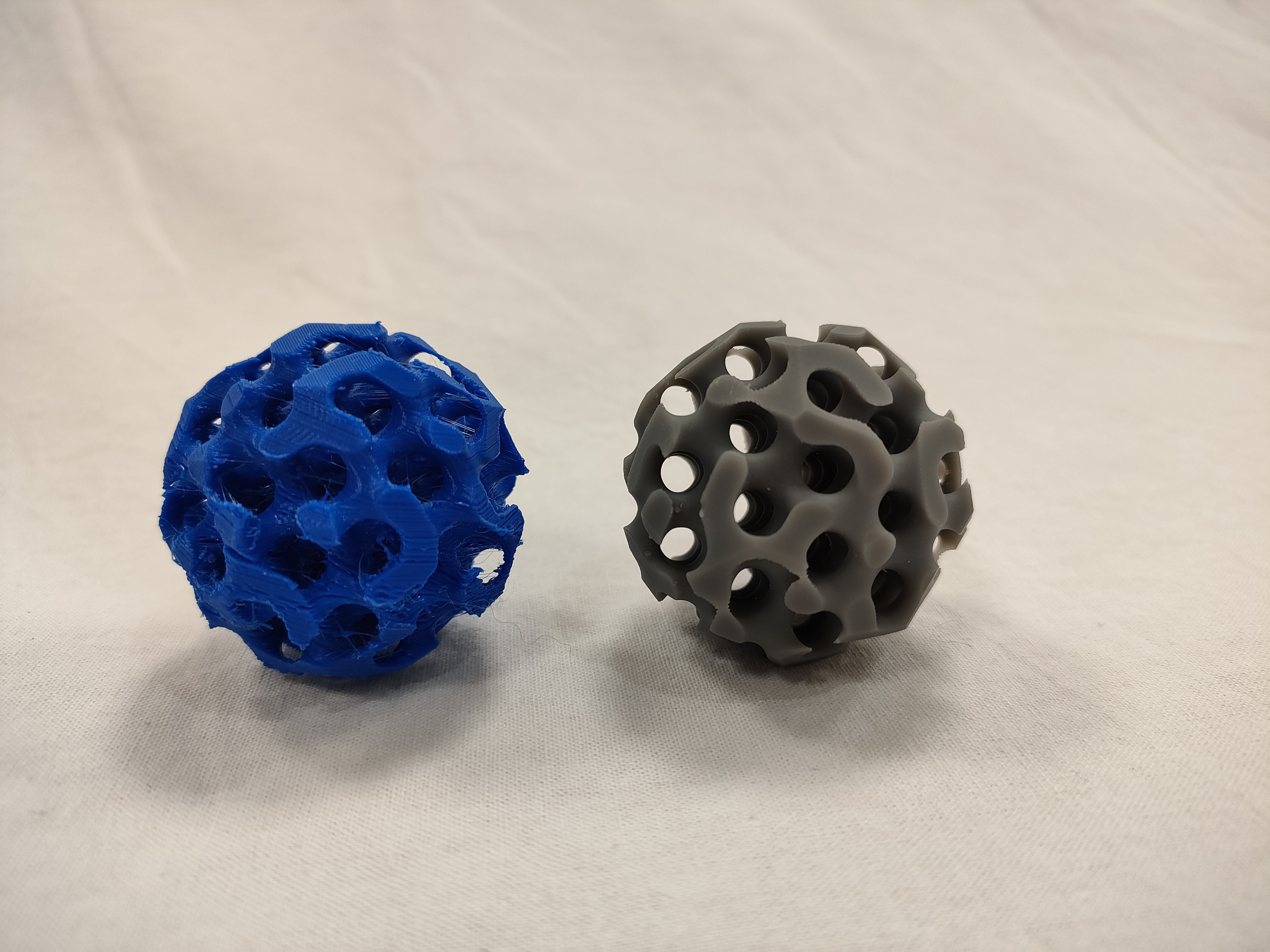
The image shows the printed part with standard parameters and with optimized parameters. As you can see, the manufacturing parameters (especially temperature and speed) affect the quality of the parts, not only depending on the material used but also on the geometry of the part. In any case, some post-processing operation can be applied to improve the quality.
Stereolithography
For the printing of this object in this technology, a standard gray Formlabs resin was chosen.
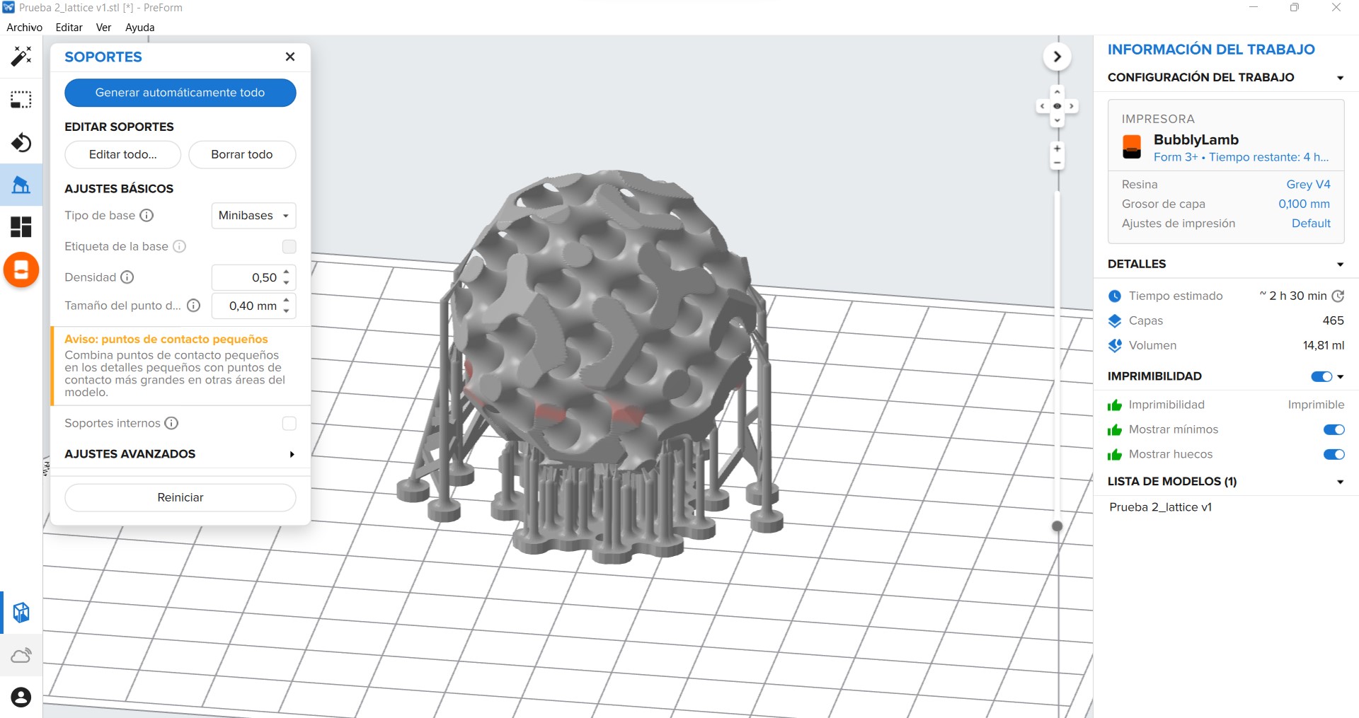
To print the part, the file in stl format was imported into the Preform software. The main parameters used are shown in the table below:
| Parameter | Value |
|---|---|
| Layer thickness | 0.05 mm |
| Layers | 923 |
| Support | Active at the base |
| Type of support | Minibases |
In this type of machine, the modification of manufacturing parameters is very restricted. Practically only the layer height and supports can be modified.
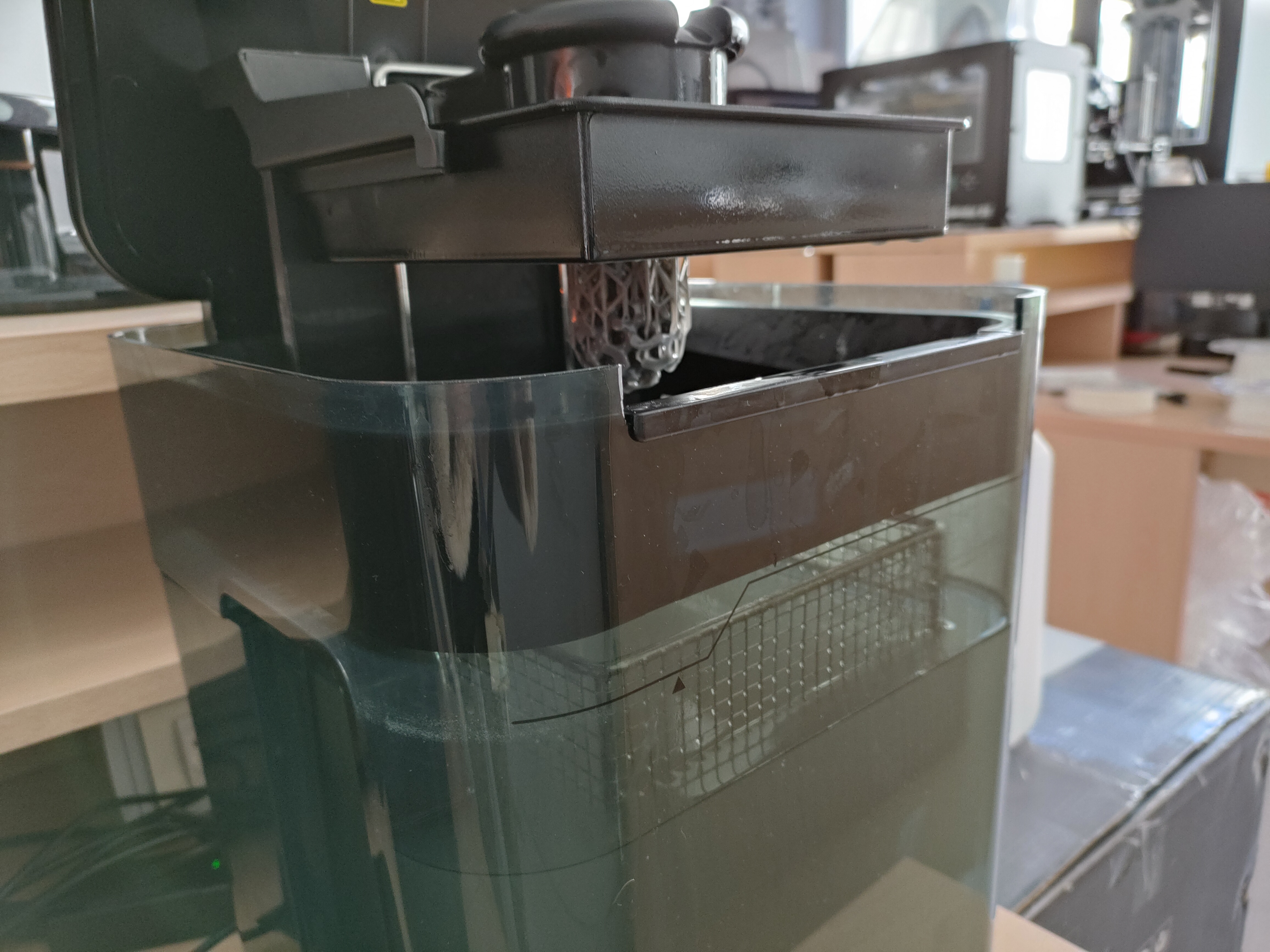
The Form3 printer from Formlabs was used to print the part. The printing time according to the software was approximately 2 hours and 27 minutes, with a material consumption of 16.11 ml.
Once printed, the part should be subjected to a cleaning cycle in isopropyl alcohol for 20 minutes. This should be done without removing the part from the base. Then, it should be removed from the base and subjected to a curing cycle for 60 minutes at 60ºC. This should be done taking care not to remove the supports, as the supports help to eliminate residual stresses and prevent changes in geometry during curing.
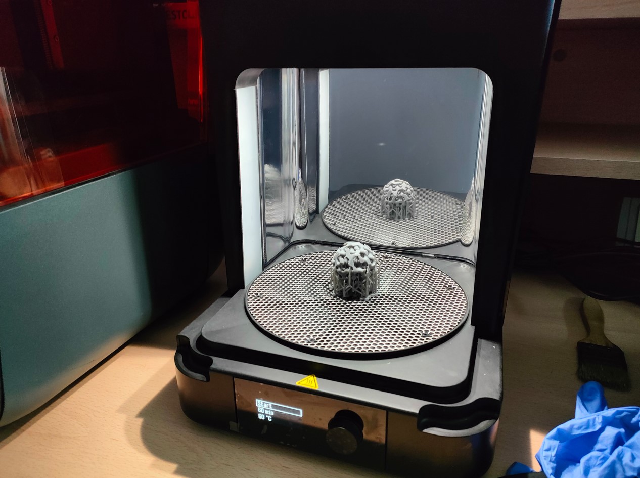
Observing the results, a very satisfactory and more accurate finish was obtained than with the other technology.
Manufacturing results
More satisfactory finishes were obtained using the SLA process than FDM. The fact of using a lower layer thickness in the SLA process is one of the main reasons, in addition to being a more precise and better finishing process than FDM. However, it should be noted that it also has an intrinsic finishing technique (isopropyl alcohol bath), which helps to achieve a smoother and more uniform surface.
To choose a technology, it is always good to make a needs assessment. That is to say, FDM technology offers us some very interesting advantages such as being able to use a greater variety of materials, besides being a more economical technology in terms of machines and materials. In addition, there are also post-processing techniques that can help us to obtain better qualities.
Therefore, even though worse results have been obtained, I recommend FDM over SLA in general terms.
Conclusions of design for additive manufacturing
Design for manufacturing is an indispensable aspect of product development. Designing for additive manufacturing, from my point of view, is a change of mentality, since this group of manufacturing processes has restrictions and advantages that had not been seen before with conventional processes. The optimal design of a part in additive manufacturing will depend not only on its shape, but also on the positioning or orientation on the printing bed (due to the anisotropy of the process), the slice size or layer thickness used, and the printing paths. In addition, with topological optimization we can manufacture more complex, weight-free, one-piece structures.
3D Scan
For scanning, different technologies and equipment have been tested. I was able to compare some of the main advantages and constraints of each.
Different objects were also used, with the intention of evaluating different data acquisition characteristics (shape, colors, dark areas, etc).
Photogrammetry
Photogrammetry is a technique used for studying and precisely defining the shape, dimension, and position in space of any object, using mainly measurements taken over one or more photgraphs of that object.
Today, photogrammetry is a popular science due to its ease of application, low cost, ang good results. Based on these causes, it is becoming a good alternative to scanning.
For this work, we used the camera of a Realme 9 mobile phone.The camera specifications are listed below:
  	Main: Triple camera
	108 MP, f/1.8, 26mm (wide), 1/1.67", 0.64µm, Dual Pixel PDAF
	8 MP, f/2.2, 120˚ (ultrawide), 1/4", 1.12µm
	2 MP, f/2.4, (macro)
The software used is polycam, which has a free reduced version. This software is quite fast and intuitive, and surely offers more possibilities in its paid version. The main problem I find is that it is a "black box". This means that I have no control over the parameters used.
The results obtained depend on each object. Generally speaking, we do not capture dark areas well. However, it is the technology that captures textures and colors best.
Some of the main restrictions detected were the inability to detect transparent figures (translucent ones are partially picked up, or with a lot of noise). Another restriction is the dimensioning of the figure, since the data collected never contemplate dimensions. For this last reason, it should not be a process intended for metrology or quality controls if it is not accompanied by an additional measurement system.
One of the advantages over other technologies is the ability to capture black color (with certain limitations).
On this subject, we have published a book chapter in which we explain the steps in more detail and all aspects of the camera and the environment involved in the process in more detail. This chapter can be consulted in the following link.
Laser scanner
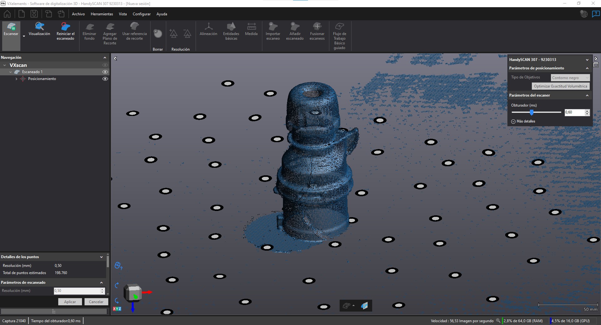
To scan an object, the HandySCAN 3D SILVER scanner of Creaform was used.
This scanner has a very intuitive software and even a step-by-step guide mode where you can scan an object in a guided way.
The first step is always to calibrate the scanner. To do this, this equipment has a calibration plate with a series of targets with specific spacing and dimensions. Simply place the scanner at the correct distance and move it gently as indicated by the calibration steps in the software.
In addition, this scanner lights up in different colours to indicate whether you are positioned at a good distance, too close or too far away from the target. We can also see in real time the data we are getting, so we know if we have to pass more times through an area where we have not been collected.
The next step is the definition of the environment. For this, the team brings other individual targets, which we can place on a table to define the space in which we are going to place our object. These targets will then easily define the planes from which we want to remove information. This step is not necessary, but it makes it easier to remove noise from objects in the environment.
Then, we can place the desired object on these targets and directly add a point cloud from the software. We can define several parameters including the resolution of the object, which will depend mainly on the number of points collected. In this case we have used a low resolution (1 mm) to obtain an object comparable to the other methods and also to obtain a file with less weight.
Once we have collected all the desired points on the surface of the object, we can finish scanning. Then, delete the environment from the positioning targets. Finally, the software itself has the option to remove unneeded points and close the model to export a completely closed stl.
This scanner is very fast and easy to use. The main drawback of this scanner is its price. It is a medium-high range scanner that reaches a geometric accuracy of less than one hundredth, so it is used in metrology and quality control.
Structured Light Scanner
Structured light is a precisely calibrated pattern of white or blue light that the 3D scanner projects onto the object it is scanning. Typically, this pattern is composed of parallel lines or a grid.
When the structured light is incident on the surface of the object, the light pattern is distorted as it strikes the curves, recesses or reliefs of the object.
The scanner's camera captures these distorted light patterns frame by frame (all around the object) as they are reflected, and the scanning software analyzes the patterns and uses them to accurately reconstruct all surfaces of the scanned object in 3D.
For structured light scanning we use David 3 software, since the equipment consists simply of a webcam and a pattern projector (obtained with the equipment itself).
The software captures image by image the deformations taken around an object. Therefore, it was placed on a turntable, to facilitate the rotation without moving any element of the system. Images were then taken every 30 degrees. Once all the images were taken, they had to be aligned, eliminating all the external elements (from the background, for example) that had been acquired unintentionally. Then, the result is merged, and this software offers the possibility to close the holes. The results can be exported in stl, obj and ply format.
The main advantages of this type of scanner over a laser scanner is the possibility of obtaining textures and colors, with greater precision than photogrammetry. However, we have a greater volumetric limitation and it is a slower process. In addition, in order to obtain an object with quality, it is necessary to have two cameras focused at different angles, to obtain as many possible orientations of the object, and thus generate fewer dark areas. In photogrammetry, this is simply solved by taking pictures from different orientations.
Group assigment
The group task is available at the following link: GroupAssigment
Files
The files for 3D printing are included in Sketchfab. The photogrammetry files cannot be obtained because the free software only allows exporting the video included in this page. To export the model in stl and other options of the software, you have to pay. Two of the objects scanned with the laser scanner have been included.
The Test part.
The printed part.
The laser scanner result.
Another laser scanner result.