4. Embedded programming
Introduced to embedded programming
An embedded system is a computer system (a combination of a computer processor, computer memory, and input/output peripheral devices) that has a dedicated function within a larger mechanical or electronic system. Modern embedded systems are often based on microcontrollers.
This week we started learning basic notions about computers and how they work, from what is a bit and bytes and binary code, as well as how to apply it.
We have been introduced to embedded programming, that is, how to program electronic components to do what we want them to do.
Despite being an engineer, I had no knowledge of electronics, and some very brief knowledge of C++ programming. I had worked with Arduino without understanding anything about what it did, just copying some libraries.
In Barcelona, they explained us different boards with different microcontrollers and we started to program with BArduino.
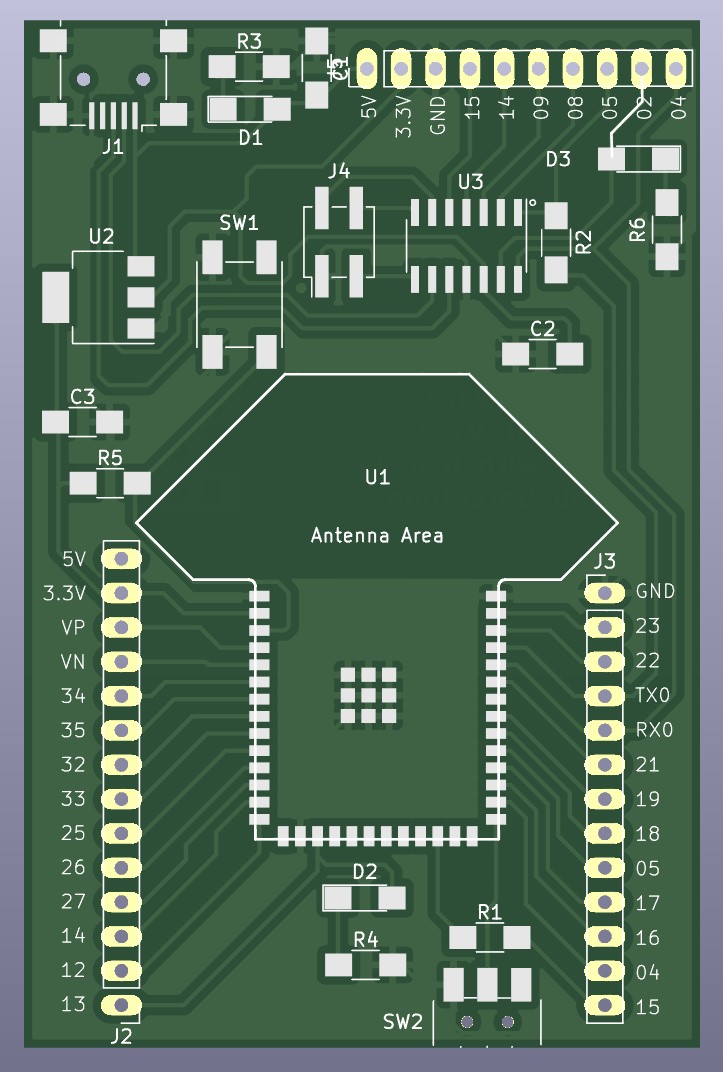
Barduino 3.0
This is a development board by Barcelona Fab Lab (Fab Lab BCN) for an ESP32 microcontroller together with an ATSAMD11C14A. The main idea of this project is to use the SAMD11 as a Serial bridge to program the ESP32, but being able to program both microcontrollers on one board with the usable pins open for prototyping, that provides an easy way to experiment and prototype new electronic designs.
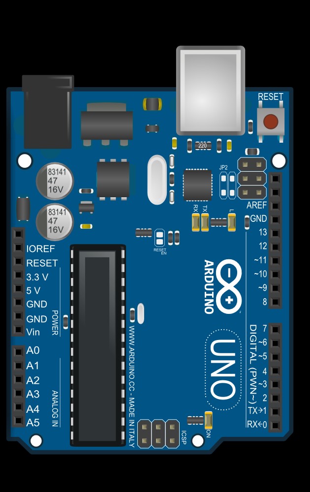
The main differences between an Arduino and a Barduino are the pin layout and the microcontroller chipset. The Arduino's microcontroller was 'ATmega328P' and the Barduino had an 'ESP32' and 'ATSAMD11C14A' microcontroller. This forced us to download additional boards from the board manager in Arduino IDE in order to communicate with the Barduino. We also downloaded Arduino, which is a software application used to program code on the Arduino microcontroller development boards.
In the following image we can see on the left an Arduino board, and on the right a Barduino board.
Barduino has 2 microcontrollers that we can start to program in our Individual assigment:
- SAMD 11: it has USB communication, it has micro connections, power, ground, and 2 pins for information.
- ESP32: it has a lot of memory, wifi, and Bluetooth embedded, but it doesn't know how to talk to the USB.
Individual assigment
As individual tasks we have had to do several things:
- Learn to identify the ideas needed in a data sheet.
- Learn about Barduino.
- Programming the microcontroller SAMD11C14A.
- Programming the microcontroller ESP32.
- Testing.
- SAMD11
- ESP32
Here I reviewed the SAMD11 data sheet to better understand what is going on in it.
I had never looked at an integrated circuit data sheet before, so I found it quite tedious. I relied quite a bit on Fab Academy summary documentation to get me started to understand, and then I could go straight to looking at the data sheets. Also, I watched some video tutorial on YouTube on how to go through a datasheet.
As I mentioned, the board I had is the Barduino 3.0 with an ESP32 microcontroller paired with an ATSAMD11C14A that will be used as a serial bridge. This is because the ESP32 does not have the ability to do direct communication, so the SAMD11 will be the translator.
To program the virgin SAMD11 you have to upload the bootloader and configure it as a serial bridge.
First I connected the SWD (Serial Wire Debug) programmer to the Barduino 3.0 and then both to the PC. The SWD programmer is a protocol used to debug and program microcontrollers. Next, I opened the terminal and used the command below to upload the bootloader to the SAMD11.
edbg -ebpv -t samd11 -f free_dap_d11c_mini.bin
With this step, I am now able to communicate with the SAMD11 through the Arduino IDE.
Having the SAMD11 programmed, it can be used as a serial bridge to establish contact with the ESP32 microcontroller.
To do this, turn on (to the left) the small switch on the bottom of the board. This means that the board will boot up in flash mode ready to receive the code, but I had to press the reset button on the top right before uploading the code. Once the code was uploaded, I set the switch to the right and then hit the reset button, then the ESP32 worked.
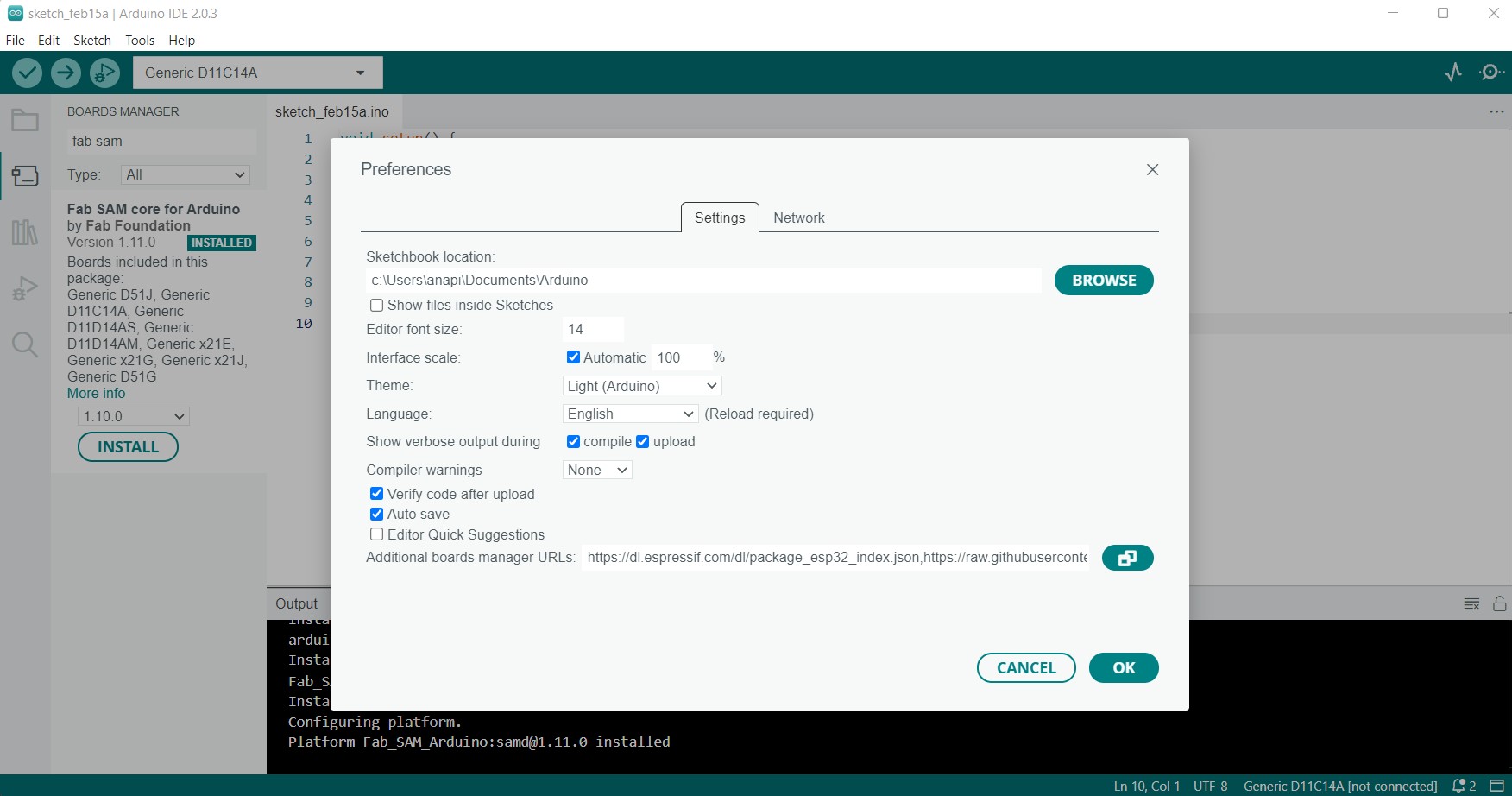
For testing, I had to install Arduino IDE and the necessary boards to communicate with the ESP32 and SAMD11.
The following links were copied and pasted into the URLs in the Arduino additional board manager in preferences so that the IDE would find them.
https://raw.githubusercontent.com/qbolsee/ArduinoCore-fab-sam/master/json/package_Fab_SAM_index.json
https://dl.espressif.com/dl/package_esp32_index.json
I started using one of the Arduino examples. A simple one that was to easily control the blinking of an LED. I simply updated the code to map the pin to the correct pin on my board. In SAMD 11 the led pin is number 2.
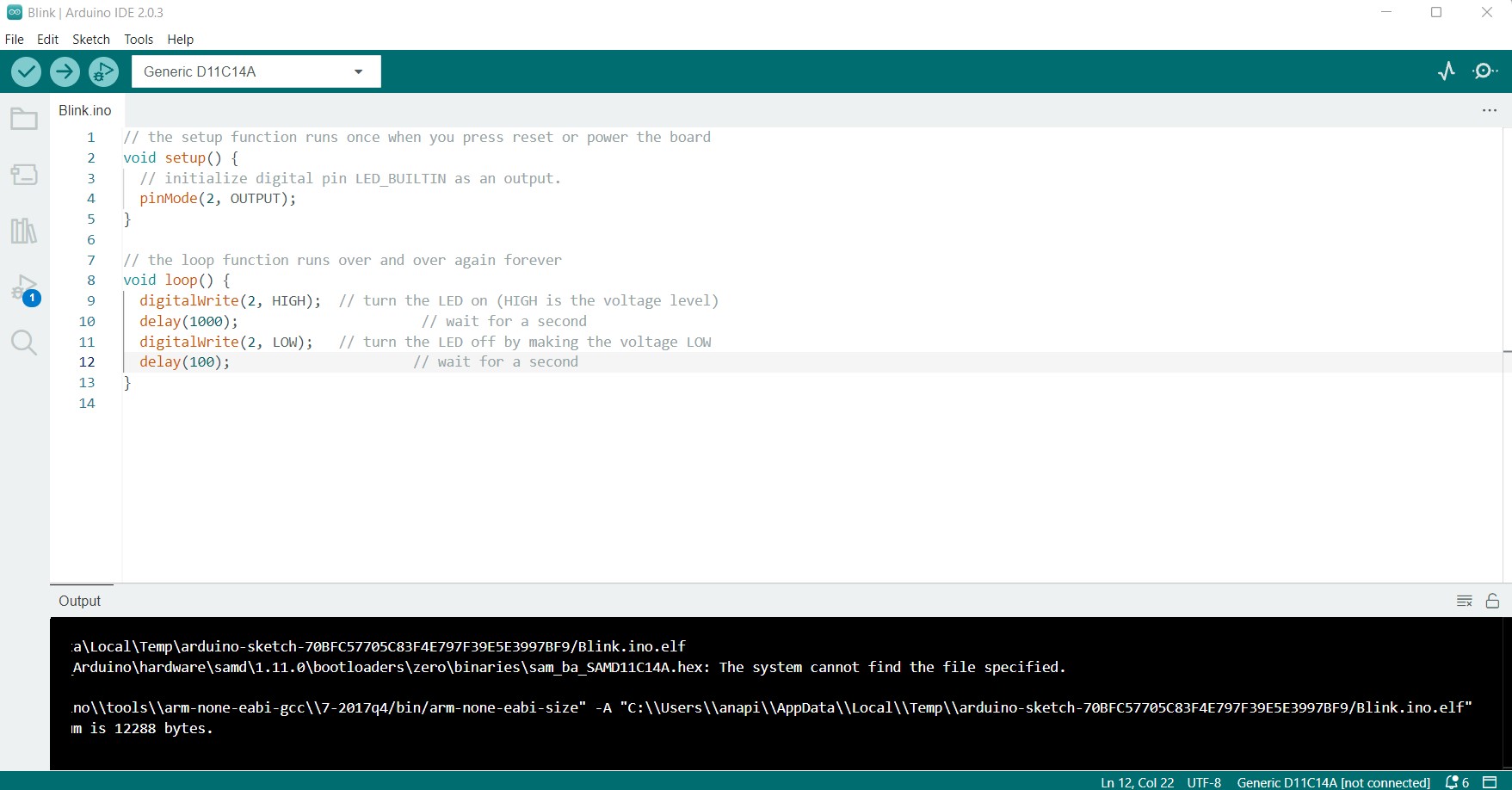
A detail to take into account in Arduino is that the ON/OFF must be indicated as HIGH/LOW or just 1/0.
In this code, we have 2 functions (usually based on C++ ):
- Void setup(): says that whatever is inside it is executed once, in this case, we are saying that PIN 2 is the OUTPUT, and this information stays forever (until we have a different code sent to SAMD 11).
- Void loop(): which is looping, so it is continuously executing, a function we need to be able to see state changes over time.
void setup () {
	pinMode(2, OUTPUT);
}

void loop() {
	digitalWrite(2, HIGH);
	delay(1000);
	digitalWrite(2,LOW);
	delay(100);
}
To also check that the communication with ESP32 was correct, I changed the SAMD11 board to the ESP32 board in the Arduino software, and tried the same example code above.
This time I updated the led pin to 13 (the ESP32's pin) and used a faster blink (100ms).
void setup () {
	pinMode(13, OUTPUT);
}

void loop() {
	digitalWrite(13, HIGH);
	delay(100);
	digitalWrite(13,LOW);
	delay(100);
}
Finally, some other assumptions were tried, but all based on very simple codes with the LEDs even at the same time. I need to work more on the programming of these boards in the weeks ahead.
The following video shows how I made the above two codes work together.
Group assigment
The group task is available at the following link: GroupAssigment
For this part of the assignment, my role was to study the SAMD 11 microcontroller and talk about its architecture.
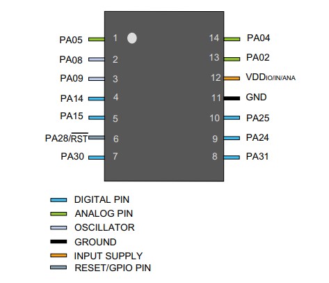
The Atmel® | SMART™ SAM D11 is a series of general purpose and low-power microcontrollers using the 32-bit ARM® Cortex®-M0+ 32-bit processor, the one used by us (SAMD11C14A) with 14 pins with 16KB Flash and 4KB SRAM. SAM D11 devices operate at a maximum frequency of 48MHz and achieve 2.46 Coremark/MHz. They are designed for easy and intuitive migration with identical peripheral modules, hexadecimal compatible code, identical linear address map and migration paths between all devices in the series.Specifically, in Fab Lab Barcelona we have used the SAMD11C14A microcontroller.
The following image shows a detailed view of the SAMD11C board.
Reading the datasheet
The datasheet of a microcontroller (or any electronic component) contains detailed technical information about the features and specifications of the device. From my point of view, the important aspects that can be found in the datasheet of a microcontroller are:
This week we have learned how to quickly analyze in these long datasheets where this information is, which is the most important information to be able to design a board.
I also have to say that I started programming without having read the datasheet and that gave me a lot of problems and errors. My recommendation is to always have the datasheet close by and especially the schematic of all the circuits.
The most typical beginner's mistake I have made several times is to try to program the pins with the pin number indicated on the datasheet, not the programming number. The datasheet provides detailed information about the pins of the microcontroller, including their function and configuration. If the datasheet is not consulted, it is easy to misconfigure the pins.
Microcontrollers often have timer and counter modules that can be configured in various ways. The datasheet provides information on how to use these modules correctly, including how to configure the relevant registers and how to calculate the appropriate time values. In this case I did not make a mistake, but because it was a detail that was anticipated by my instructors.
Finally, failure to consider the current and temperature limitations of the microcontroller can lead to device damage or unpredictable behaviour. By reading the datasheet, you can obtain important information about the safe operating characteristics of the microcontroller and ensure that the design meets specifications. In this case the SAMD operates at 3.3V and therefore requires a voltage regulator as it will be powered from the computer.
Conclusions
We have learned some basic notions of programming, seeing that the same architecture allows us to have a wide range of microcontrollers depending on the functionality we need. Choosing one microcontroller or another will depend on the need for the specific job we want to do and the user's experience.
I think I need to learn a lot more and acquire concepts about electricity and electronic components especially. Also about programming in arduino, which seems quite simple, but I lack practice, especially to be able to deal with my final project, among many others in the future.