3. Computer controlled cutting
Design

For the design of the individual task, we have chosen to use Grasshoper software, as recommended by my instructors.
The first design idea was to make a kind of 2-dimensional puzzle that could be used in two different ways. So, we thought of a typical game for small children and combined it with an almost traditional puzzle.
Then I wanted to design an almost traditional puzzle (from a different geometric base) could also be stacked vertically, so as to have a game similar to a jigsaw puzzle.
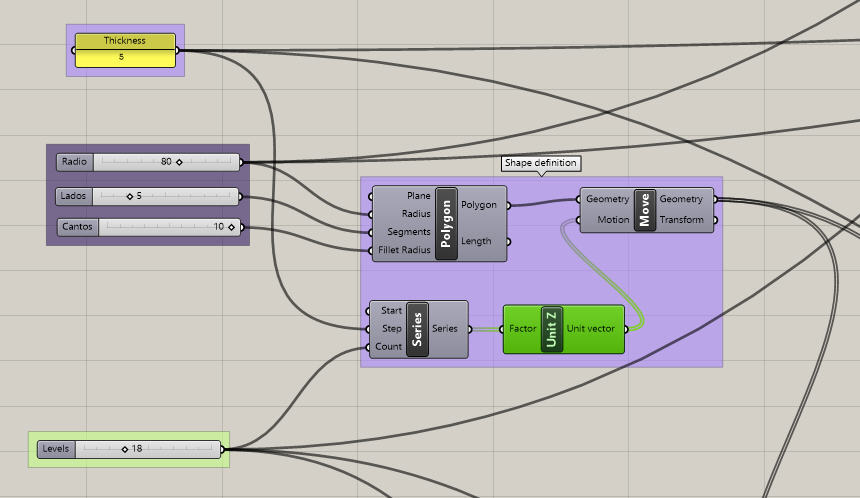
From this initial idea, we started to design parametrically in Grasshoper. Considering that the puzzle can be any polygon.
The image shows the process of designing a (regular) polygon of "n" sides (which we can round the corners), repeated several times (levels) to which we have given the thickness of the wood veneer that we plan to use in the laser cutter.
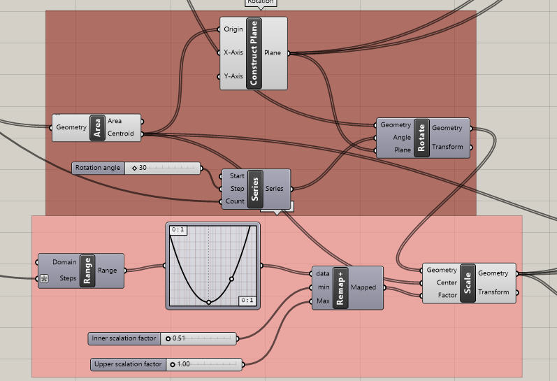
The polygons repeated on the central axis have been rotated by an angle of rotation (defined at 30º for the production of the model) and their size has been modified with respect to a function (see the following image).
Once all the pieces of the vertical puzzle were in the desired position, a similar figure (a rectangle) was designed in all the pieces in order to insert them in that fixed position, as in the children's game.
the piece that will join all the others is defined by the width of that rectangle (the height is fixed and has the value of the thickness of the wood to be used) and the total length that will be equal to the sum of the thicknesses of all the pieces used in "levels" plus a margin of 30 mm.
Finally, in the center of each side of the polygon (minus one), some rectangles were designed (alternatively on the contiguous sides) to fit the pieces in 2D, as if it were a traditional puzzle.
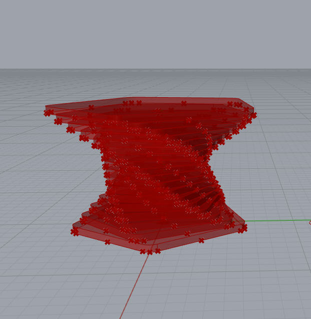
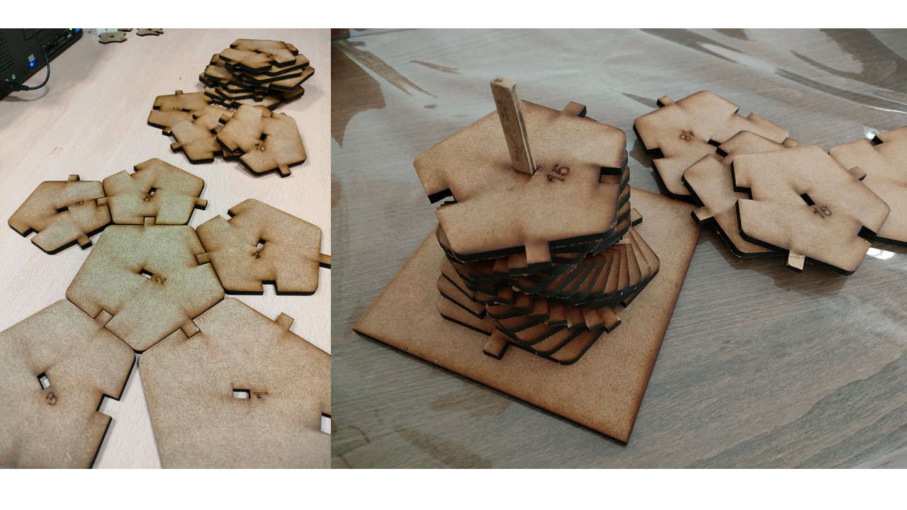
The image shows the column created by all those extruded and rotated polygons, stacked in the desired position.
Below is a video showing the design process of the grasshoper part. In it we can see the main variables on which my product has been designed. Thus, we can distinguish mainly:
- Radius, of the circle that inscribes the first base.
- Sides, number of sides of the polygons that we are going to have.
- Rounding, rounding radius of each vertex of the polygons.
- Levels, number of times we repeat the polygon on the Z axis.
- Rotation, rotation of each polygon with respect to the previous one.
- Two factors of the graph that defines the function that scales the scale of a polygon with respect to its contiguous ones.
Laser cutter
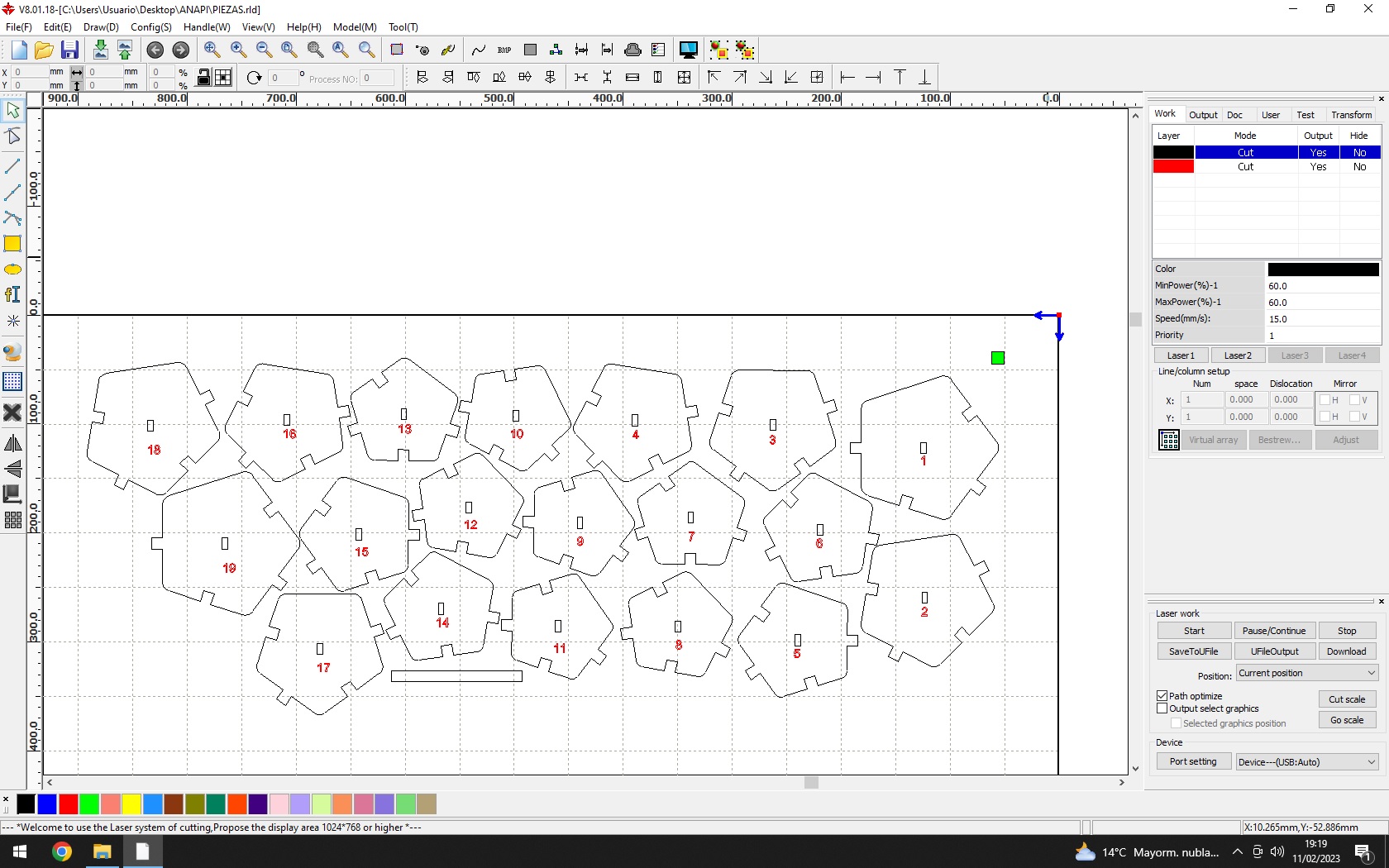
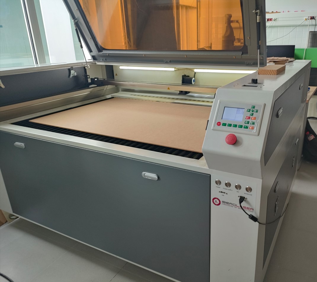
The laser cutter used is from IBEROLASER. For this, the previous models were baked in Rhinoceros and exported in DXF (it is also possible to do it in DWG).
With these 2D designs, we worked in the machine-specific software RDWorks.
First, a number was inserted to define the position of the piece in the vertical puzzle, with the idea of silk-screening it.
Subsequently, we tried to place the pieces in such a way as not to waste too much area of the plate, and to obtain remnants that were easy to reuse.
For this purpose, two layers were defined: a black cutting layer and a red texturing layer.
Correct adjustment and focusing of the laser on a laser cutting machine is crucial to obtain accurate, quality cuts in the material. The following are the steps to properly focus the laser on a cutting machine:
1- Focus distance selection: The first action is to determine the optimum focal distance for the laser cutter lens based on the thickness of the material to be cut. The focus distance refers to the distance between the tip of the lens and the cutting surface. This choice is crucial to ensure the quality and accuracy of the cut.
2- Cutting table height adjustment. On this machine it must be done with a pattern. When the laser is focused correctly within the circle of the pattern, both the distance from the table and the focus are correct.
3- Checking the beam path: Check that the laser beam is focused on the cutting area correctly. For this purpose, a visual check can be performed.
4- Performance of cutting tests.
Below is an image of the machine used and the tests carried out in the lab for different materials.
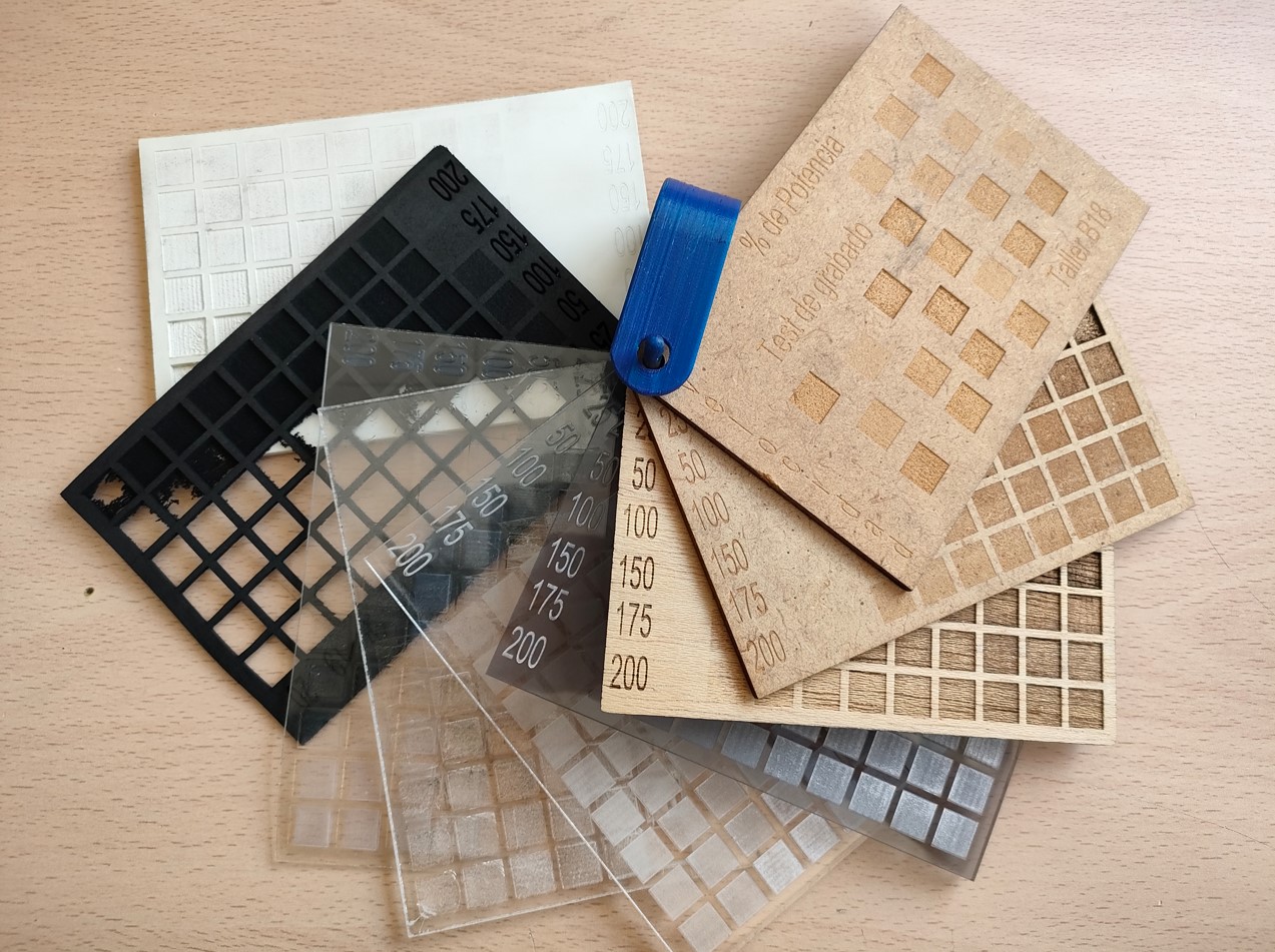
I started making my parts. To focus on the material I used, I consulted some references or patterns that we have in our FabLab that indicate the cutting and engraving qualities in many materials based on the power and speed used. For my work, I just consulted these patterns that I made when the machine arrived at the Fab. These parameters are defined in the following table. However, the mistake was not the parameters, but the manufacturing tolerances.
| Parameter | Power [%] | Speed [mm/s] |
|---|---|---|
| Cut | 60 | 15 |
| Texture | 30 | 100 |
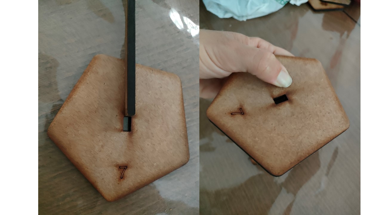
I did not take into account in the design the space or gap (Kerf) for the pieces to fit (as you can see in the image, they were forced to fit until they broke). Fortunately, parametric design allows us to quickly change these values and thus make the parts fit perfectly.
Although the press fit of the objects can be achieved by modifying the parameters, in this case and given the parametric design, it was decided to make two "combs" similar to those of the group assigment but specific to my material.
The tests showed that the Kerf required for a tight fit was between 0.05 and 0.1 mm, so the second option was chosen. We could also have chosen an intermediate value.
Another defect that can be observed in the piece is the stains caused by the lack of smoke evacuation. The material chosen, which is a resin with wood chips, requires a more powerful smoke extractor than the one currently available. However, with a little sanding, the surface is perfect.
Final model
After practicing with the tolerances in the group task, the necessary tolerances for this material were known. Thus, a model was obtained that fit in its 2 positions.
Final model in DXF.
Vinyl cutter
To test the vynil cutter I decided to practice with something like origami.
For this purpose, a rhombicosidodecahedron has been chosen from the Thingiverse website.
From this model, I have made its flat layout with the SLICER for Fusion 360 program. The construction technique used is "folded panels". It has been adjusted to A4 format.
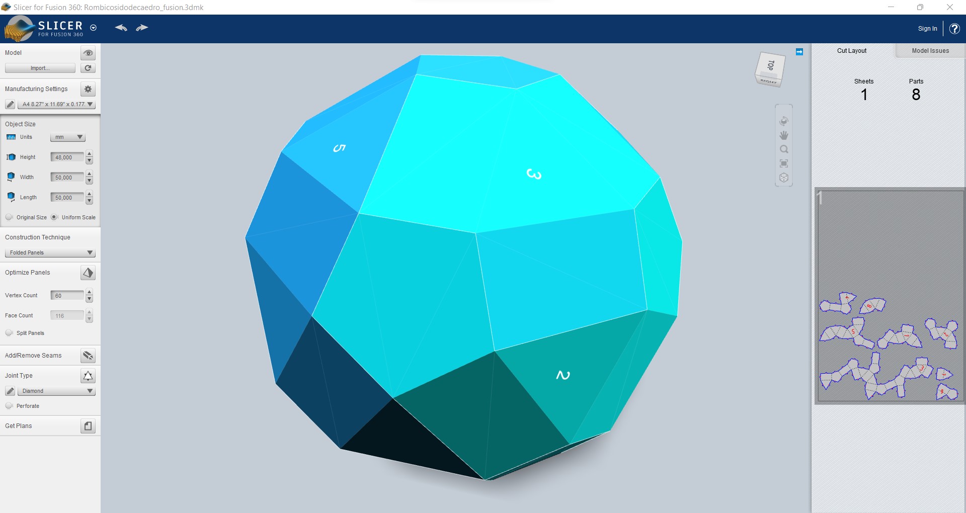
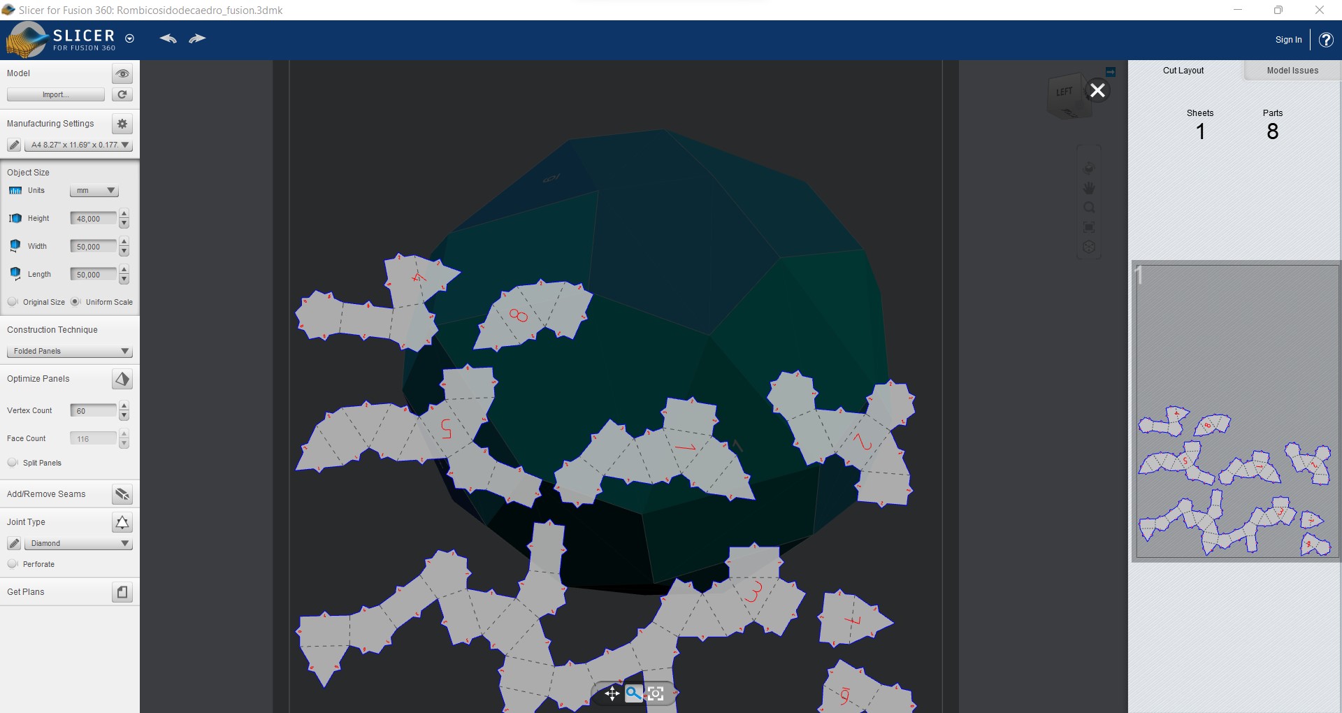
For the object to fit in this format, it was too small, so I enlarged it to 80 mm in height. In this case, the program does not perform a good nesting, and even if it could fit in a single A4 format, it splits it. Therefore, the Inkscape program has been used to make better use of the cardboard that was used.
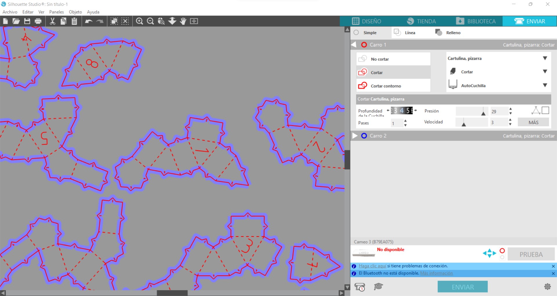
Finally, the DXF drawing is loaded into the vynil cutter program, Silhouette Studio. This format will have 3 defined layers.
Once we have the files we will follow the next steps:
1- Select the file. Commonly used compatible file formats are DWG, DXF, SVG, EPS
2- Align the vinyl. The sheet to be cut must be perfectly aligned on the cutter's work table.
3- Set up the cutter: Adjust the cutter settings according to the type of vinyl and thickness of the material. Set the speed, pressure and other parameters necessary for proper cutting of the vinyl. Those used in this case are listed below:
| Slice / Parameter | Tool | Force | Speed |
|---|---|---|---|
| Cut (blue) | Cadstock, plain - 4 | 20 | 2 |
| No-Cut (black) | Cadstock, plain - 1 | 7 | 4 |
| Sketch (red) | Pen | 7 | 4 |
4- Upload the desired file to the cutter's cutting software and verify the cutting settings.
5- Start cutting.
6- Remove excess material: Once cut, the excess material must be removed from the sheet using a stripping tool. As cardboard was used, one's own hands are sufficient.
7- Assembly the parts.
The last step is to glue the parts together to be assembled. The main problem obtained for this complex figure is the small size of the gluing flaps. In addition, the last piece becomes impossible to put on as no pressure can be applied in the gluing area. Therefore, I recommend that anyone making origami with completely closed surfaces use tongues that fit into slits and make assembly much easier.
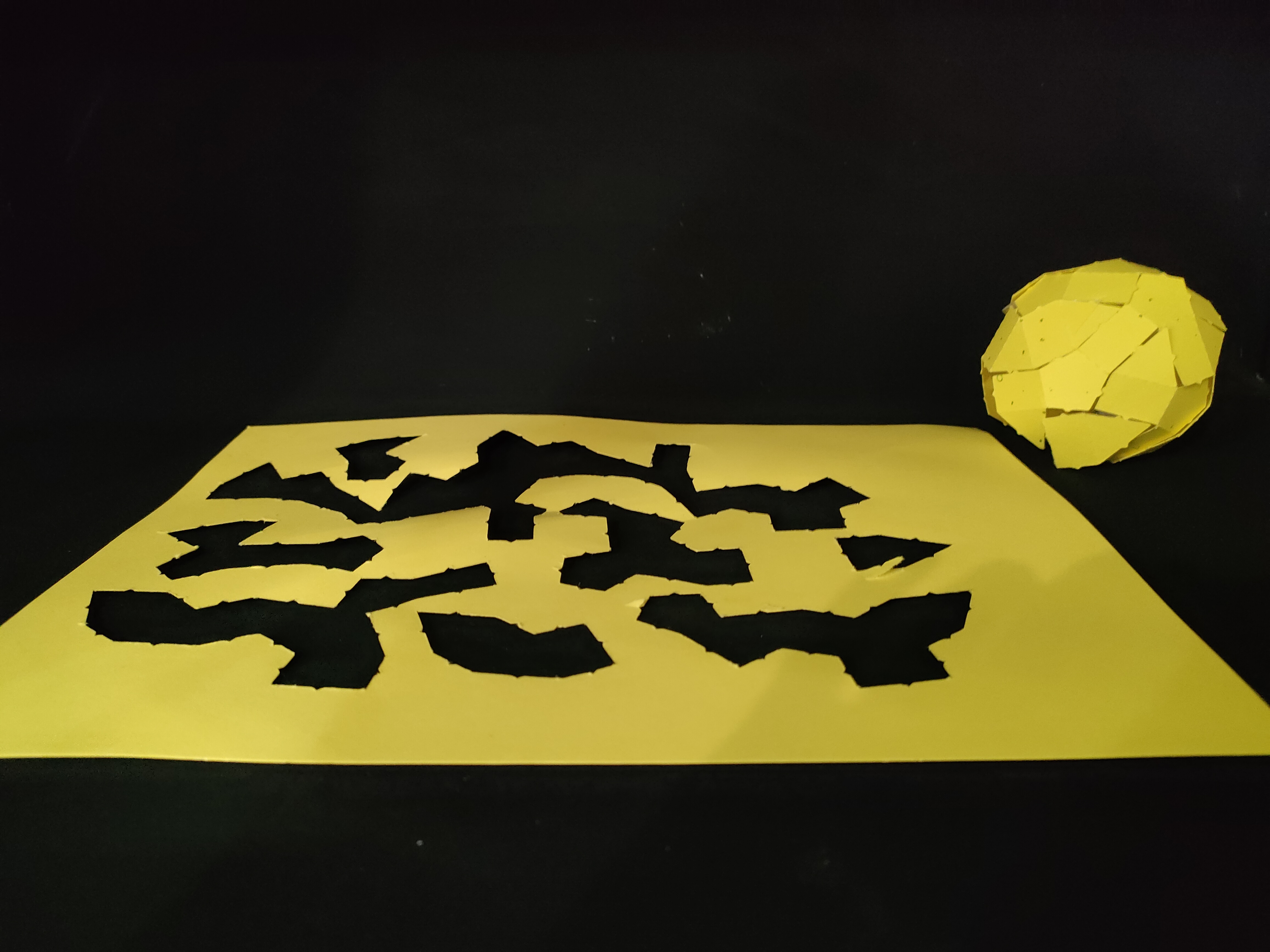
Final model in DXF.
Files
The files have been uploaded at this public link.
Group assigment
Here ypu can see the information about the Group assigment work.