2. Computer Aided Design
What is CAD?
Computer Aided Design (CAD) is the representation of objects or spaces on computers that completely changed engineering or graphic expression.
The term was coined by Douglas Baumann in 1959 and used in 1960 in an MIT draft project entitled "Computer Aided Design Project".
Object representation in CAD applications
The working mode of the CAD applications varies significantly whether it is a 2D or 3D application. Some of the main differences are listed in the following table:
| Programme | 2D | 3D |
|---|---|---|
| Objets | Two-dimensional: lines and regions | Three-dimensionals: Solids and surfaces |
| Work plan | Only one | Several |
| Coordinate system | Bidimensional | Three-dimensional |
| Point of view | Only one, drawing plan | Anyone |
| Visualization | Symbology and line display | Various types of visualization |
Software evaluation
This week I worked on the use of different 2D and 3D CAD software.
The following are the lists of some of the main or most widely used programs, and a discussion of which ones I have used and how.
Software 2D
There are different 2D CAD software. Some of the most widely used are:
Inkscape

Inkscape is a free and open source vector graphics editor. Inkscape can create and edit diagrams, lines, graphs, logos, and complex illustrations. The main format used by the program is Scalable Vector Graphics. It can be used to design images, and above all it is used to vectorize logos, for example.
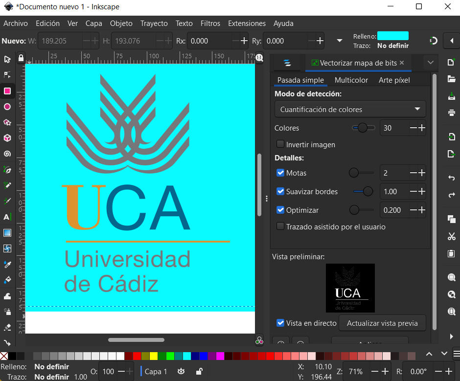
The 2D design of figures has been tested with this program. However, I like more and I am more used to 3D design software where we can also draw on a plane. Therefore, I have used this program mainly to vectorize the logo of my University.
The vectorization is very simple since the program recognizes color changes, light changes, borders, or create the lines we want. Depending on the mode used, we can see that we automatically get the expected result.
Also, I have inserted several layers and applied transparency, a layer with a turquoise rectangle, and another layer with the logo.
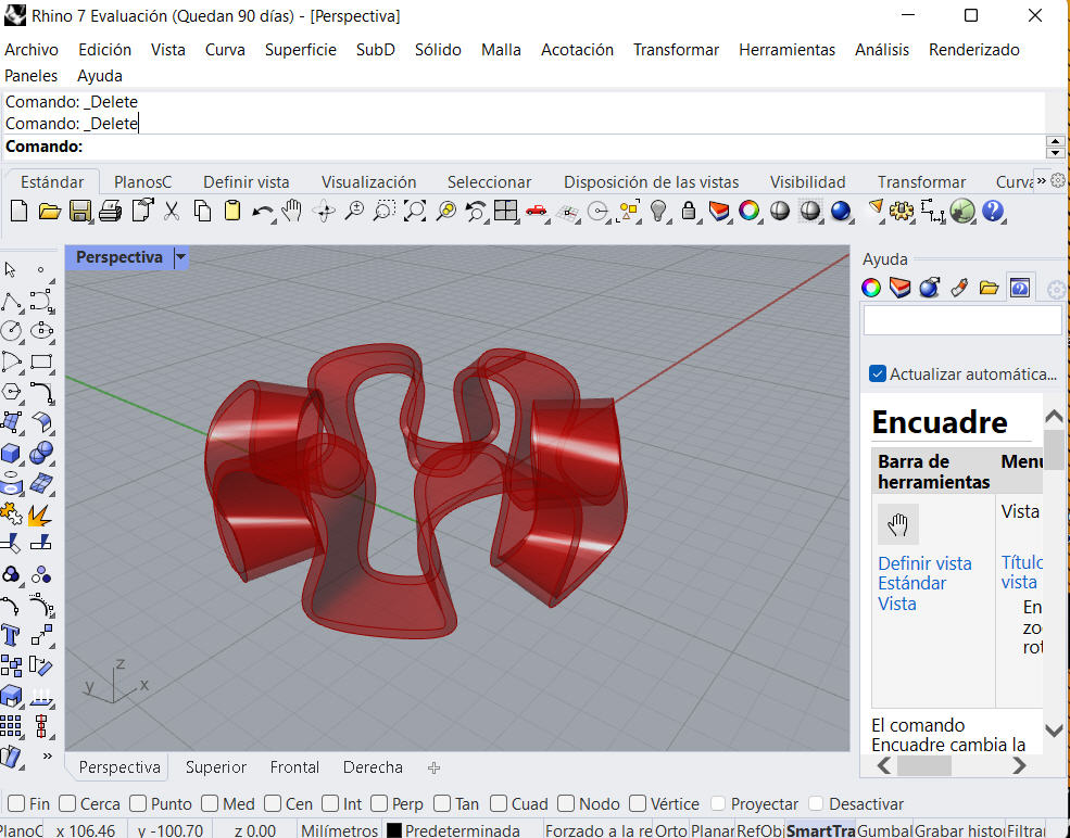
However, be careful with automatic vectorizations from a pixelated image, as the smoothing causes the vectorization to not perfectly match the image (as shown in the figure).
QCad
QCAD is a free, open source application for computer aided drafting (CAD) in two dimensions (2D). With QCAD you can create technical drawings such as plans for buildings, interiors, mechanical parts or schematics and diagrams.
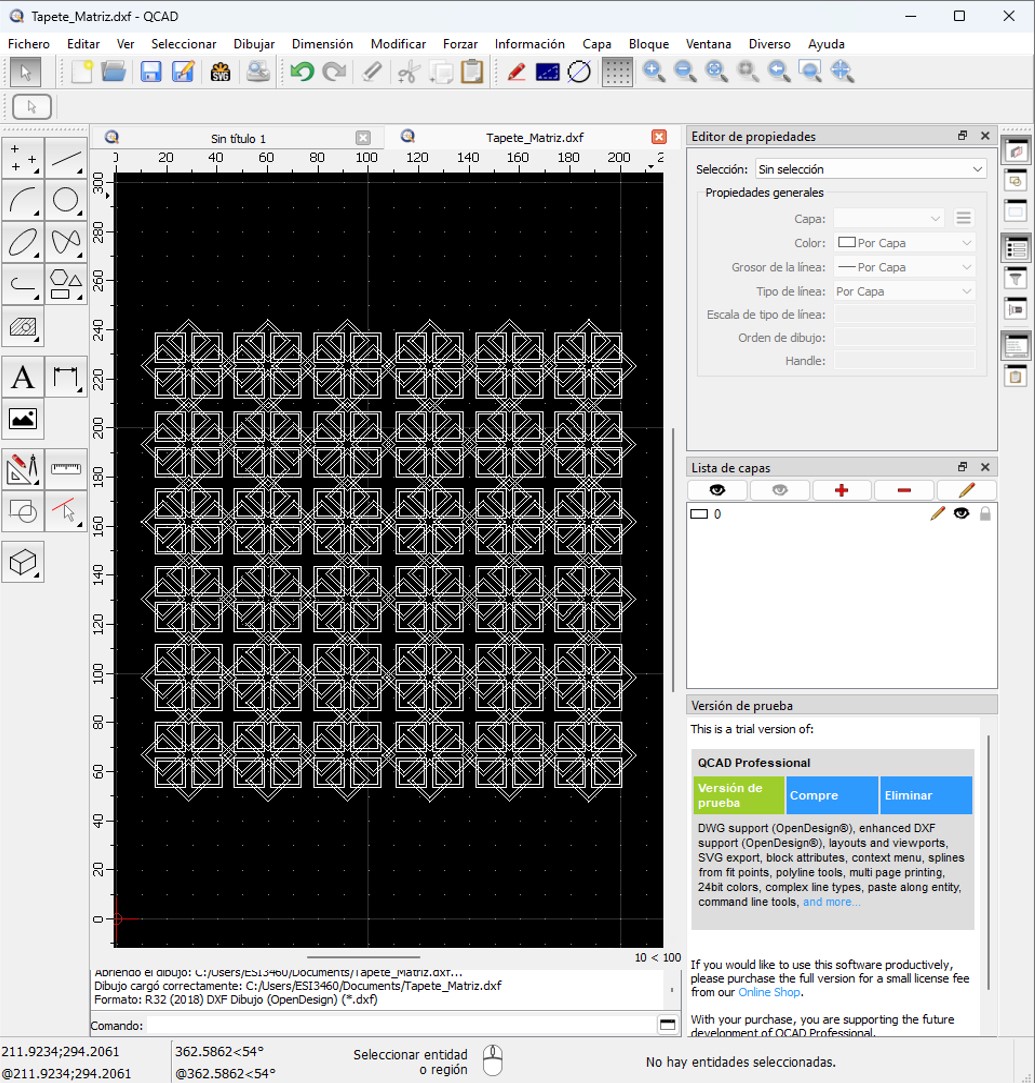
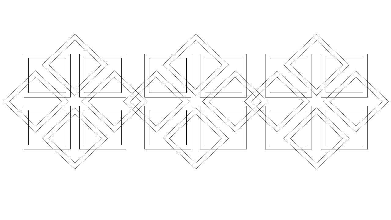
QCAD was designed with modularity, extensibility and portability in mind. Therefore, making modular patterns is very simple from a geometric figure.
I have also noticed its intuitive user interface. QCAD is an easy-to-use 2D CAD system where no computer-aided design experience is needed.
With this program I designed some patterns intended for my possible final project, as shown in the figure. I started with some very simple geometrical patterns, which I was complicating to give certain properties to the part in the future. When we start with the machining, I will check if they work as I expect.
Software 3D
There are different 3D CAD software. Some of the most widely used are:
Blender

Blender is a multiplatform computer program, especially dedicated to modeling, lighting, rendering, animation and creation of three-dimensional graphics. Also digital compositing using the procedural node technique, video editing, sculpting (including dynamic topology) and digital painting.
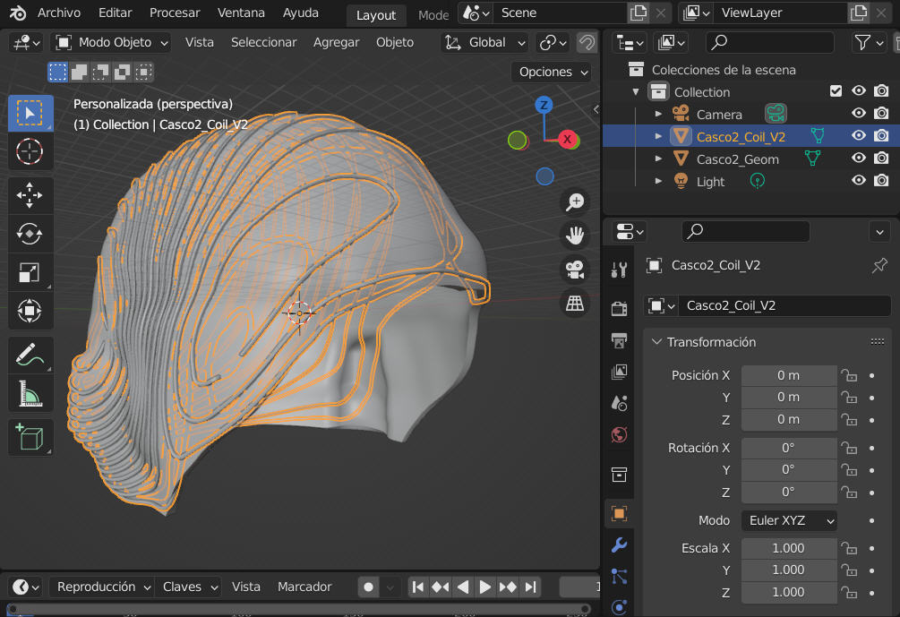
Blender is a program that allows to design by basic modeling (from a 2D or simple geomeric figures). However, it also allows sculpting to make a more artistic design.
In this case, this program has been used to make a helmet design from a skull model typically used in medicine. From the skull, the helmet has been sculpted (eliminating all the inner area and leaving a gap of 3 mm that represents the scalp). Then, some coils have been designed on the surface of this helmet and a bolean operation has been performed to obtain the helmet with the holes for the coil.
As can be seen in the image, blender allows complex surfaces and boolean operations. This program also allows many things and that is why it is widely used in the world of film and animation.
Catia

Catia is a commercial computer-aided design, manufacturing and engineering software made by Dassault Systèmes. The program is developed to provide support from design conception through production and product analysis. Catia was invented for the aeronautical industry, and is widely used in the automotive industry. Because of my academic background and professional experience, it is the design software I have used most often.
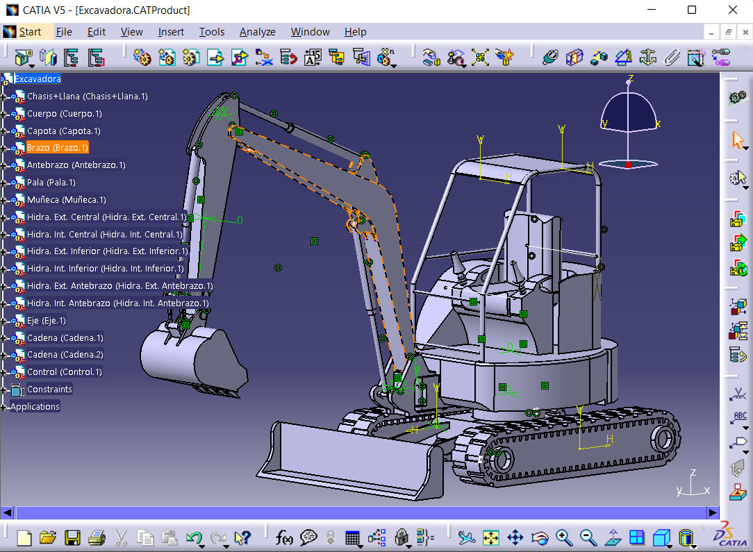
As I am used to work in this program, and it is commonly used for product design, I have designed a complete excavator.
For this, I have used several design modules: Part design, Generative shape design, and Assembly design. The first two are used to design parts, and the last one to assemble them and check that they fit correctly.
In the case of Part design, I usually work from 2D or sketcher drawings. However, in the surface module it is more common to use wireframe geometry. To assemble the parts and check that there are no clashes it is best to have any designed part converted to solid.
Grasshoper

Grasshopper is a graphical algorithm editor that is included in Rhino. Unlike many coding languages or other programming languages, Grasshopper does not require a programming background. At the same time, it allows designers and architects to create algorithms to generate design alternatives. This means that it is the ideal program for parametric design.
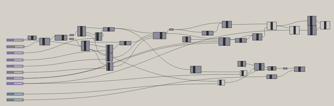
In this software, the lower part or support of a design table has been designed. The idea of this parametric table is that it could be adapted to the living room of any house, so that with very simple changes we can edit the height or upper diameter where the table top would later be supported.
To do this we first designed a lower circle, so we have the variable "diameter". From it, we define tangent curves to the support plane and that had continuity in tangency, so we would have another variable "number of curves". These curves have a maximum amplitude or height, which is defined by another variable.
With the integration of more variables, we can make more complex solids. In the image below we can see the tree used to design this parametric table that we can modify very easily.
Conclusions
After having worked with several programs, Catia, which is the software I usually use in my work, is still the most comfortable for me. However, parametric design is easier to modify in Grasshoper, and it is an option that I will like to explore further. In this case, a bit of "clueless" work has been done. As for 2D design it is always possible to work with specialized programs for it, which give many possibilities for adaptation, lights, coloring, etc. However, and perhaps a little by "professional deformation", I still prefer to use 3D programs on the plane, such as AutoCAD.
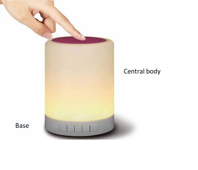
Possible Final Project
For the project it has been decided to use Inkscape and Catia for 2D and 3D design respectively. This choice was mainly because they were already known software and I have more ease or speed in the development of the models.
Finally, I have decided to make an interactive light game. This game will be built from two main pieces: the base and the central body. The base will be designed in 2D with the intention of cutting and engraving it on the laser machine. The main body and what would be the complete prototype will be designed in 3D.
2D Design
The design of the base was done in Inkscape. On the one hand, it is intended to screenprint the flat base, which would be the one that supports the product. On the other hand, we wanted to design 2D cuts in a rigid material (wood) that would allow the piece to bend and thus form a kind of brocade cylinder. Some of these patterns were designed in QCad software.
The logo obtained previously (UCA logo) by testing with the different programs was used.
In order for the wood to bend easily, alternating linear cavities must be generated and aligned in the opposite direction to that in which the wood is to be flexed.
Some of the proposed designs are shown in the image below.
To generate a 2D pattern it is only necessary to define a geometry to be repeated. In my case, so that they all had the same "unit cell" size, I created a rectangle in dashed lines to delimit the working area of the drawing to be repeated. Once drawn, just make a rectangular pattern that repeats the entire unit cell on the X and Y axis, leaving no spacing between the beginning and end of each cell. This was tested with different patterns leaving very diverse geometric figures.
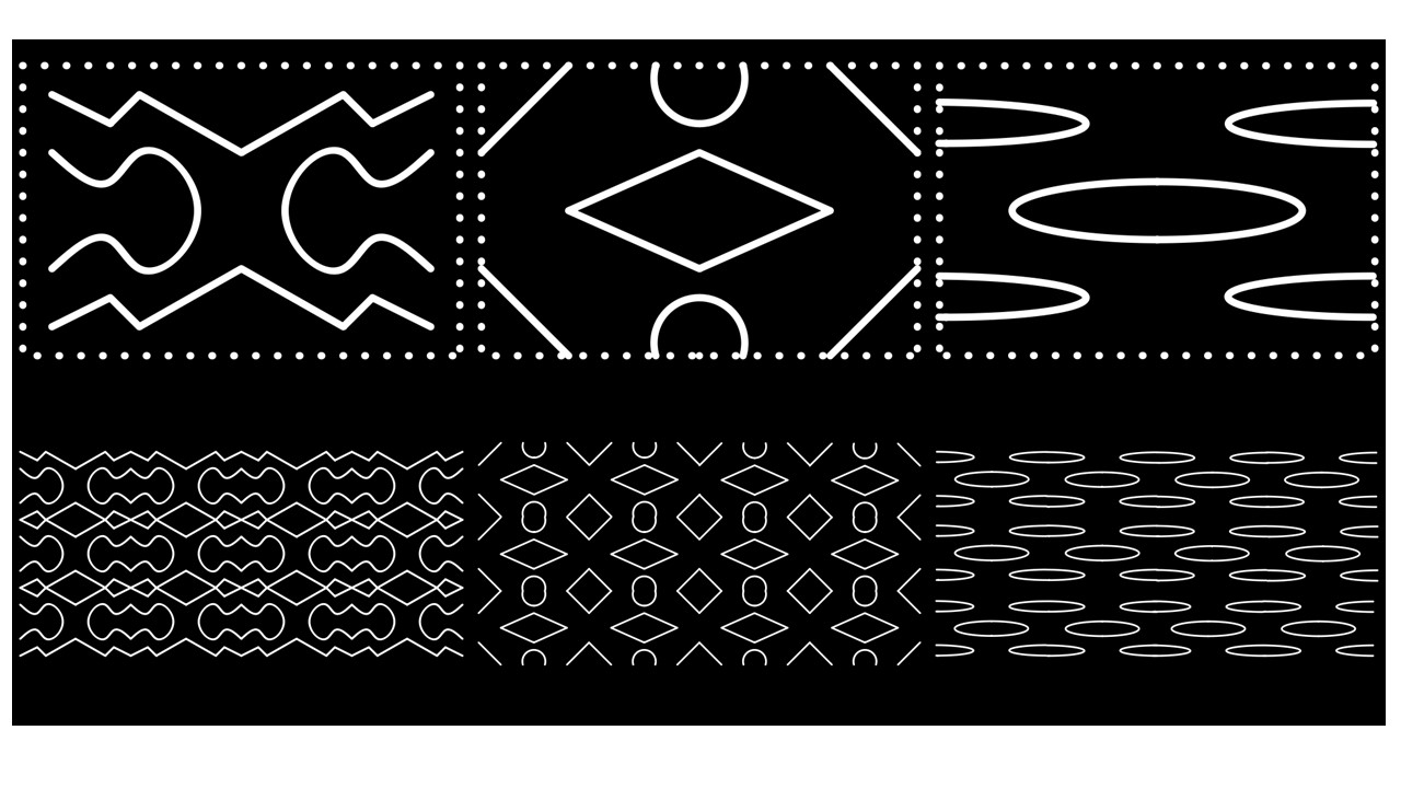
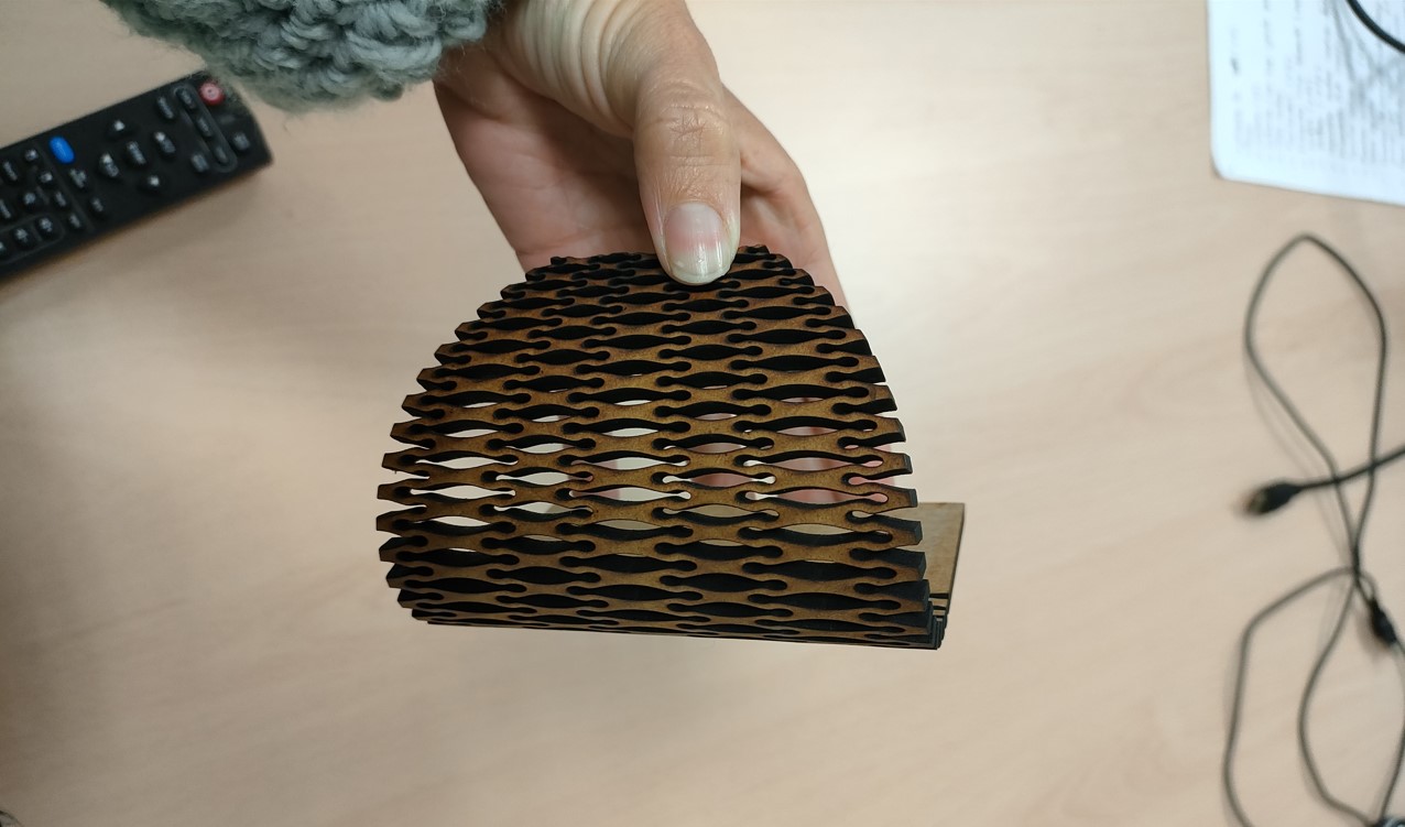
Also, some of these patterns were cut to test that they met the desired functionality.
3D Design
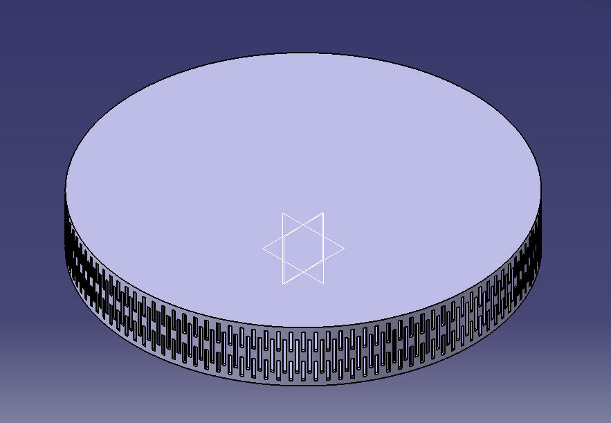
The design of the main body and the complete product was made in Catia.
The parts were made with the Part design module and assembled with the Assembly design module. These parts can then be joined or separated for the different manufacturing processes.
For example, the base of the game (where all the electronics will go) has been made by means of a revolution. Then, the chosen pattern can be applied to it. An example pattern is shown in the image.
In this case, a simple rectangular-shaped slit was made (in vertical position), and a material removal operation (pocket) was performed. This operation was given a "circular pattern" in which we can designate the axis of rotation (which will be that of the revolution itself) and the number of repetitions and the separation between them. Also, we can repeat the pattern in parallel, so that some holes are also stacked on top of others, in addition to repeating radially.
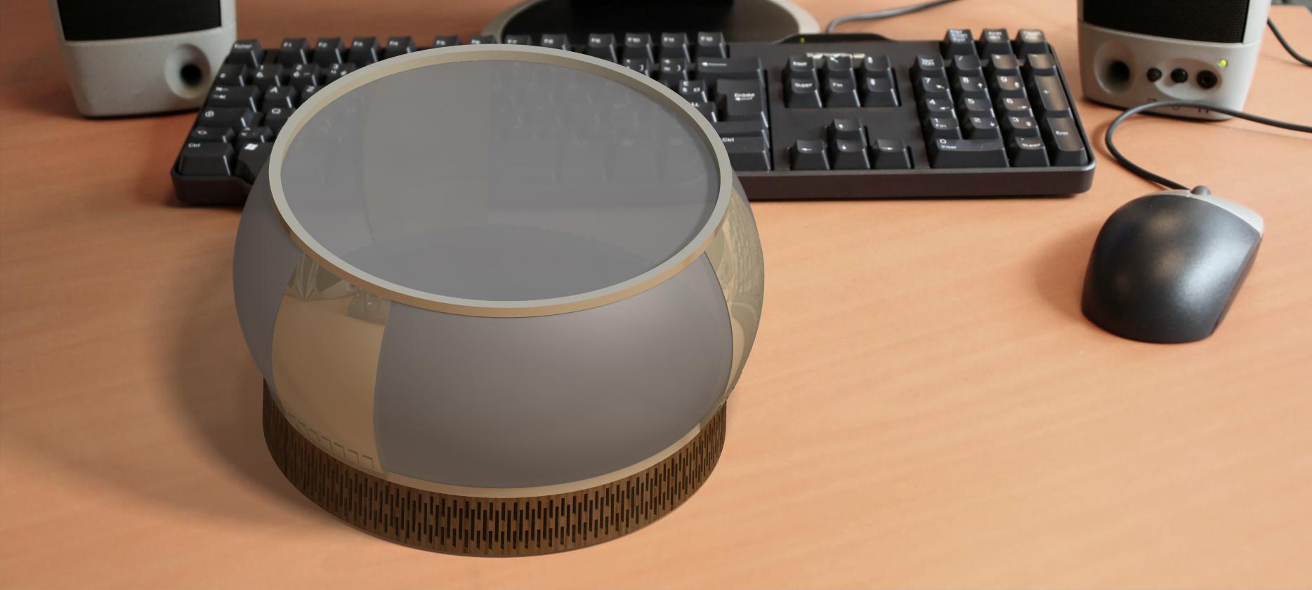
In Catia I can assign materials to see what a product would look like. Also, to know the approximate weights with densities provided by the program. On the other hand, although it is not a specific program for rendering, it also does it. Thus, an idea of the final product is presented in the image below.
When we make a rendering in Catia, we can see the assigned materials, give a background that integrates the product and play with lights and shadows until we find the visualization that we like the most. In this case, I tried to integrate the product in a desk table, I gave some transparency to the main body and assigned wood to the support where the electronics will be integrated. This will not be the final project but it serves to have a first approximation to the desired idea.
Files
Some of the Sketchab models created below are included.
The file format generated in some programs is not compatible with Skecthfab, so some of the pieces have been uploaded at this public link.