This week we will make our own circuit boards again, but now with an output device attached to it. Output devices not only being screens or leds, but also (stepper) motors and (piezo) speakers.
to learn / to do
Group assignment:
- Measure the power consumption of an output device
- Document your work to the group work page and reflect on your individual page what you learned
Individual assignment:
- Add an output device to a microcontroller board you’ve designed and program it to do something
looking ahead
what I already know
Not much really. I know the terminology, like led, lcd, tft and oled and in broad lines their differences. I played around with conventional speakers when I was younger, and also with a piezo speaker. My desktop cnc has stepper motors, but I am not really sure what that means.
what I want to learn
This week I want to try out some ideas I have for the Tide Monitor. There is one idea I have for creating a kind of impressionistic display of the state of the sea (calm or rough). Or, maybe I can experiment by creating waves in a body of water. Something that involves a servomotor and a potmeter I am guessing.
the process
Erwins Lecture
Erwin told us about different output devices.
Displays
LED
Light Emitting Diode, we have talked about this already. It sends light when turned on.
LCD
Liguid Christal Display. Pixels are turned on/off by reversing polarity. A turned on pixel is black/dark. It is reflective, which means it does not emit light. It is typically used with a light shining behind it. For example, the Mario’s Cement Factory game I used to have when I was young
 I still miss it
OLED
RGB LED pixels in a very high density
VFD
Also from the past, this was popular in de 80’s, in VCR displays for example
 I remember
Apart from the display technology, there is also something to say about the arrangement:
Single color LED
Just one led light. Comes in different forms, for example the bigger through hole LED’s, or small smd LED’s. There is also a diffused LED that emits a softer light.
Multi color/RGB LED
In fact three LED’s together: red, green and blue. They share a common anode or cathode, so a RGB LED has 4 pins in total. It is advised to have a resistor for each LED pin. There is also a digital RGB LED which has its own microcontroller, which you can chain. These are commonly used in light strips.
 RGB LED on the left, digital RGB LED on the right
7 segment display
This can be LEDS, but also LCD or VFD. Contains of 7 segments that can make up a digit.
You can see an example of this in Mario’s Cement Factory where it is used to display the time. Or on your old clock radio. Or in the image below
Dot matrix
LEDS or dots in a matrix, with rows and columns
 7 segment display on the left, dot matrix on the right
Motors
DC Motor
Basic motor, give it 5V and it starts spinning. If you reverse the direction of voltage (i.e. the wires) you reverse the direction of motion. But this is typically done with an H bridge switch, a circuit that lets you control the direction. A standard motor is a AC motor (alternating current).

Servo Motor
A DC Motor combined with a gearbox and a sensor. The servo motor uses feedback to control the motor’s speed, position or torque. The output shaft of this motor can be moved to a particular angle, position and velocity that a regular motor does not have.
Stepper Motor
A stepper motor is commanded to move to a specific location in degrees without the need for feedback. It uses a fixed wheel of electromagnets for this. It gives a very precise motion and is used in 3D printers and also my CNC 3018 at home.
PWM
Pulse Width Modulation.
Although I heard this term also two weeks ago when we where playing with LEDs, Erwin elaborated on this a bit more this week. It is a method to get analog results with digital means. A digital signal is either ON or OFF. But what if you want to make a fading LED? There is where PWM comes in. Basically you turn it ON/OFF in a very high frequency so the eye averages the “on” time and perceives a change in intensity and not blinking on and off.


Group assignment
Measure the power consumption of an output device. For this, Henk and Erwin created a setup for us that involved an Arduino with an Arduino Motor Shield to control 3 different stepper motors. Henk programmed the Arduino to move the stepper motors for a certain amount of time, like 20 seconds.
The Arduino itself was powered by 5V output of a USB hub. The Arduino Motor Shield that controlled the stepper motor had its own power source that was controllable.

We set it for exampe to 24V or 12V or 5V. With 24V the motor ran very smooth. But on 5V you could see and hear the motor having troubles. You could also see that the motor needed more current (Ampere) when the Voltage was lower. This makes sense, as the Power that was need to run the motor is the product of Voltage * Current.
We could see that the motor needed more power (current, as the voltage was fixed) when it was rotating, but needed power anyway even when still. This is because the electromagnets in the stepper motor are on to keep the motor in a fixed the position.
We measured the current that was needed to power just the Arduino Motor Shield, without stepper motor attached, this was about 0.013A.
Then we measured the current that was needed to power the motor, just to keep it still. This was 0.080A. The current that was needed to have the motor in motion was 0.101A . Then we tried to keep the motor from spinning, to see what that would do. The ampere went up to 0.116A.
We repeated the process with a stronger motor and this gave us the following values:
- idle: 0.088A
- running: 0.111A
- blocked: 0.155A
The voltage during this tests was 12V.
Individual assignment
I want to make a board that drives a motor, not sure yet to be a dc, servo or stepper. Maybe all of them. This is a test for my end project, that might need motors or a pump. But in essence, a pump is also a motor. To be able to control the motor speed, I want to use a potmeter.
I took a couple of motors home from Waag, to play with during the weekend. I have Arduino stuff and breadboards at home, and I figured I would make a test setup first, before even thinking of designing the PCB circuit.

In this image on the left a unipolar stepper motor with ULN2003 driver board, top middle a DC motor, bottom middle a solenoid (not a motor), top right another DC motor and bottom right a potmeter.
At home I found a little servo motor.
L298D
To play with the DC motor, I found I needed a L298D IC. This is because the microcontroller (on my own board or on an Arduino) does not have enough power to drive these motors. Connecting the motor directly will result in a fried microcontroller. The L298D on the other hand, is capable of an output of 36V, enough to drive a DC motor. Apart from that, the L298D also incorporates an H-bridge to reverse the direction of motion and PWM to control the speed. The L298D can drive DC motors as well as stepper motors, and I think I need one of these. It seems that I will be able to test both motors with my board this way.
I found a good explanation of the L298D and how to connect it here
ULN2003
I checked the controller on the stepper motor driver board, to see if that was also a L298D, but it turned out to be a ULN2003. This is what I found about this IC:
“The ULN2003 is one of the most common motor driver ICs, consisting of an array of 7 Darlington transistor pairs, each pair is capable of driving loads of up to 500mA and 50V.”
The little board that it is attached to is specifically suited to drive a stepper motor, specifically the 28BYJ-48 stepper motor. I checked, and indeed, this is the type of the stepper motor attached to it.
Again, a good explanation of this IC and how to connect it with Arduino from the same site
Tinkering in TinkerCad
Without the L298D I could not use my home Arduino setup. But I did try it out in TinkerCad. This helped a lot. First, I added the L298D, a breadboard, a DC motor and a battery, and connected them without looking at the examples.

When starting the simulation, the motor would work, but only with an rpm of 4. So I checked an example, and got to a working setup as you can see in the image below. I did get the power inputs right the first time, but did not connect the H-Bridge part correctly. In the image below these are the yellow lines that power the motor, and the light blue lines that connect to the Arduino. The dark blue line controls the speed.

With some code (TinkerCad is great btw!) I could control whether the motor was on/off , and the direction of motion:
|
|
Next step was to add a potentiometer. It took a few tries to wire it up correctly. I originally connected it to one of the digital inputs/outputs on the top, but I had to connect it to an analog IN at the bottom.

With that working, it was time to get rid of the Arduino all together. TinkerCad has an 8 pins AtTiny in the inventory, and since I had connected 4 pins on the Arduino (excluding Power) I figured that should be enough.
First I replaced the Arduino, and to replace the power source that Arduino provided I added a 3.5V battery. I did this because I knew the AtTiny needed max 5V.
It did not work. I checked the wiring multiple times, carefully checking if the code I wrote for the AtTiny went to the correct pins.

It did, altough it seemed that I had to change the name for the pin that connected to the (analog) potentiometer:
|
|
I found that as long as I kept the power from the Arduino connected, it would work. Then I realised that 3.5V from the battery was probably not enough to drive the L293D, and that I needed a better power source.

And what better power source to use that the 9V battery I already had? Ofcourse, I had to do something about the output Voltage of 9V of the battery, getting it down to the 5V that the AtTiny wanted. I used a 5V regulator for that. And then it worked! Well, in theory ofcourse.

To finish it off, I want to add a slideswitch to reverse the direction of the motor, and a LED to have a visual indication of the direction of motion. I think I can just add it to the same switch output as I have the AtTiny connected to, and directly to the LED. It is after all a switch, so no need for using the AtTiny to switch the LED on/off. It took me a few tries to get it right. The LED got burned whenever I switched it ON, complaining about too much current (481mA instead of max 20mA). But how much I tried with the resistor values, the same message kept coming back. I eventually copied the whole design and started to delete parts to see where it started working. But even when I had just the switch and the LED it kept burning out. Eventually I figured it out: I had one pin of the resistor on the same row in the breadboard as the pins of the switch. After fixing that, my LED also worked.

My final tinkercad design lookes like this:

Tinkercad also creates a schematic view of the design. I use this as input for KiCad (import non-KiCad project > Eagle project). It does not import as a schematic, but as PCB design. But when I want to assign footprints I run into trouble. The L293D is not part of the FabLab inventory.
I
Should
Have
Checked
First
A4953
What is part of the FabLab inventory is the A4953. This is a smaller and simpeler H-Bridge. It can drive one motor and does not have a dedicated PWM pin for speed. I still can use the potentiometer, but I have to use the output to calculate the PWM myself on the AtTiny and send it to the inputs of the A4953. Much like when you want to fade a LED, but in this case you ‘fade’ the motor speed.
So it is back to the drawing board, KiCad this time, and after a good while I come up with this design:

- I use an AtTiny412 for the microconttroller
- I added an UPDI connector so that I can actually program the microcontroller
- Instead of the slideswitch I use a jumper. When the jumper is ON the LED will be on and the motor will run counter clockwise
- Without the jumper, the motor runs clockwise
- The UPDI pin and the jumper pin are shared, because I did not have enough pins on this AtTiny. Henk thinks this might work and so do I. But probably only without the jumper. That is fine. When everything works, the UPDI is not in use anyway.
- I added an FTDI connection for debugging, as per Henk’s advice.
- I use 2x2 pinheaders for both the motor connector and the battery connector. I need only 1x2, but 2x2 is stronger. I use it also for the jumper.
- I added some capacitors, as per Neils example that uses the same motor driver
 PCB design. On the left you can see I added an extra outline so that my exported .svg’s have a nice margin
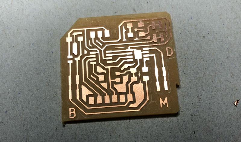
And this is what the PCB will hopefully look like. I added letters to the jumpers to keep them apart: M for Motor, B for Battery and D for Direction.
I export the PCB design to .svg. This time I add an extra bigger outline around my board in the User.1 layer. I do not export this, but it gives both my traces and my outline an extra margin so that Mods will not get confused about the board edges.
Milling
Milling was complicated this time. First, I set the milling depth for the outlines too deep: 0.025 instead of 0.0025 . So I broke the bit.
Henk gave me a new bit, and initially it seemed to go well. But when the job was at I think 75% the bit broke again. Maybe I pressed the surface a bit too much when I was levelling the bit?
Henk gave me a new one, but I somehow did not slide it high enough up in the spindle holder. I tried multiple times, because I already had a hunch about it. But I could not slide it higher. But when set the machine to move to its origin, the bit was too low anyway. So it broke.
Henk gave me a new one, and this time I managed to mill all the traces. I just restarted the old job, so for 75% it went over already milled traces, but now the last 25% also got milled.
Then I proceeded to load the outlines. I copied the “mill outline” settings to the job settings, and changed the values as I had documented them earlier. However, instead of setting the max depth to 1.55mm, I set the cut depth to 1.55mm. The bit survived just long enough to trace my outline. But then it broke. Again.
So Henk once more had to get a new bit.
The machine wanted to trace the outline twice. One is obviously enough. Turns out this is what happens when you export svg directly from KiCad. In the image below, to the left the image that KiCad exports. To the right the image that Mods needs. I will use Photoshop next time to post-process the outline .svg

using photoshop to post process the outline .svg
- Import the .svg into photoshop
- Set the resolution to 1000dpi under Image > Image Size
- Add a black background layer
- Fill the outline with white
- Optionally import also the traces .svg and invert that layer so the traces show up white against the black background
I certainly learned a lot with this milling job. Below is the end result.
 The PCB that took three 0.39mm bits and one 0.8mm bit
Soldering
Soldering went fine. I let KiCad create a BOM (Bill Of Material, Tools > Generate BOM in the Schematic Edtor)

and went shopping in the Fab inventory with it.

And here it is.
 But will it work?
Programming
A quick test reveals that I am able to program the AtTiny via UPDI. However, the 5V regulator gets extremely hot. I think it is because it is designed to regulate 9V to 5V, but it gets a 5V input during programming and testing, when is is connected via USB. I wonder if I can fix this with a diode.
After consulting with other students, this is indeed the way to go. So I proceed to cut away some coppertrace and find a diode (I use a Shottkey 1A 100V). The dark band signifies the cathode, and since current goes from anode to cathode I need to solder it so that the anode points to the regulator and the cathode to the updi connector.

But during soldering, I melt away some copper trace. This leaves me a almost too wide gap. On advice of Saco, I just use lots of solder to cover the gap. Not neat, but it does the job. Now I am able to program my board without the regulator overheating.

Next thing to test is the jumper setup. With the jumper set, the LED should light up. It does. So that is good.
Then comes the moment to actually connect a motor. And the 9V battery
I create connectors for the battery and the C motor. And write a little program to test the motor:
|
|
I upload the program, disconnect the UPDI, connect the 9V battery. But alas. No spinning motor.

Now I have two options:
- Connect the serial pins from the FTDI to my laptop so I can read the serial output.
- Use a multimeter to check if there is voltage coming out of the AtTiny pins
I go the multimeter route first. I check the voltage before the regulator. About 9V. Good. I measure it after the regulator, 5V, good. I check the voltage that goes into the microprocessor, 5V, also good. I check the voltage that leads to the 9V pin of the motor driver. Nope. Something wrong with the capacitors? I check the PCB design in KiCad. And then I see it. A tiny little white line between the two capacitor pads. I did not make a trace where there should have been one.

Apart from the failed 9V input in the motordriver, the other components worked: the jumper for the direction and the trimmer (potentiometer for the speed) where accessible and readable. Until I am able to fix the trace, this is the program that should make it all work.
|
|
Fixing the trace
Later in the week, I fix the trace by adding a little wire between the capacitors. Unfortunately, the motor does still not spin.
 fix in the green rectangle: a little wire between the two capacitors
Debugging
Even after fixing the missing trace, I still never get the motor to spin. I checked and re-checked all the traces. Checked it with Henk (who suspected a low current). Checked it with Quentin Bolsee (who pointed me to a wrong pin number in my code) and I checked it during a group assignment two weeks later with Erwin. This is a list of the things that were tested and checked:
- Are there any shorts? (no)
- Does the controller send out the HIGH / LOW values to the motordriver? (yes)
- Do the HIGH/LOW values switch when they are switched in the code? (yes)
- Is there enough voltage (9V) coming into the driver? (yes)
- Is there enough voltage coming out of the driver? (no)
We found no obvious reasons as to why it will not work. In the end, I replaced the AtTiny and the motor driver, but that too did not make a difference.
The weird thing is that sometimes, there suddenly is enough voltage coming out of the driver. But then it fades away, like a balloon that deflates. A capacitor that takes ages to charge? I don’t know. I decided to leave the board for now and who knows, maybe one day I have enough knowledge and experience to figure it out.
looking back
This week was a struggle. Many things did not go as planned: I made a design based on the wrong controller. I broke many mill bits. Designing the board took much more time than I thought. I had an overheating regulator.
But I feel this is also the week that I really learned and started to understand a lot. I may have spent too much time tinkering in Tinkercad, but that day I learned what it actually meant to select components, combine them and building a board with it.
I broke many bits, but every time I broke one, I learned something new, so they were not lost in vain.
I was able to figure out myself why the regulator was overheating, and how I could solve that.
I also was able to figure out why the motor was not running.
And next to that, I was able to document it all. I documented every day, and every important step, and it looks like documentation is now a natural part of my work process.
So all in all, this was a very good week.