The task list for this week:
- Group assignment:
- Review the safety data sheets for each of your molding and casting materials.
- Make and compare test casts with each of them.
- Individual assignments.
- Design a 3D mould around the stock and tooling that you’ll be using, mill it (rough cut + (at least) three-axis finish cut), and use it to cast parts.
Group assignment:
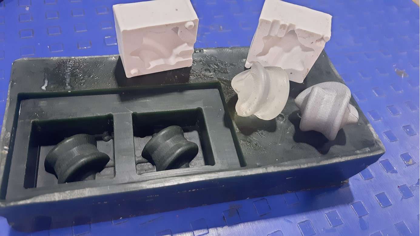
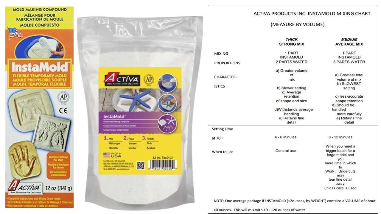
This assignment of Molding and casting week was about learning various types of materials used in molding and casting, reviewing their safety data sheets and making their test casts. each one of us went through their safety data sheets. We used all different molding and casting materials available in our Fab lab at Vigyan Ashram. I study about Insta mold .
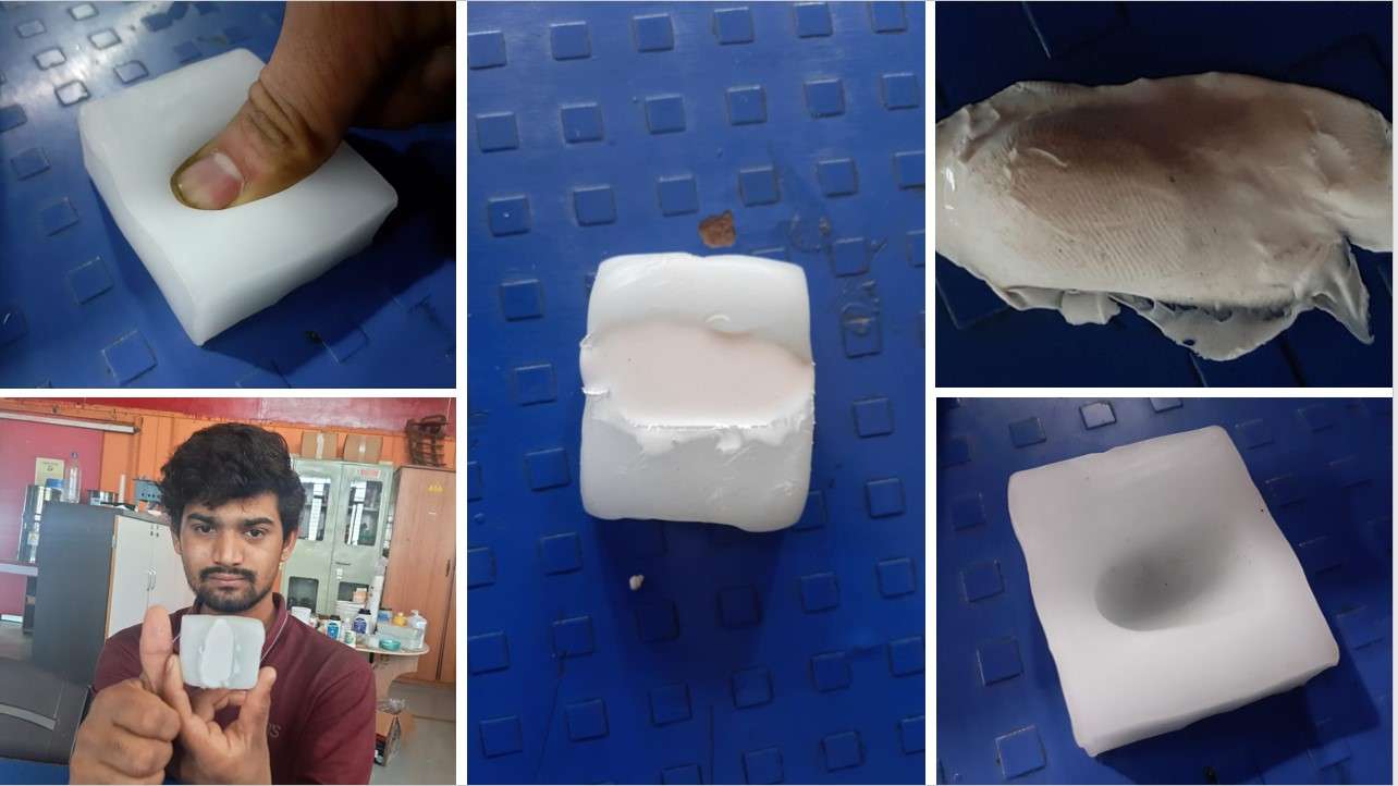
I also try to cast my thum fingerprint using flax wax and silicon. To see whether it access my cell phone or not .It print my fingerprints nicely but not able to access my cell phon . 😁
Individual assignments:
Finding Design.:
So this was a creative week so I decided to make something functional rather than a showpiece, so I started to work on finding some kind of toys that will perform some kind of task. I come through some amazing videos on youtube which show amazing toys based on some physical principles.
Some of these videos are as follows.
balancing toy
Gömböc—The Shape That Shouldn't Exist
Roll Square
Hexa Sphericons
I decided to make a Hexa Sphericons. I fall in love with the zig-zag motion. And I started to work on it.
 This is what makes the Sphericon so special:
- It can be made from a range of solids of revolution.
- While it rolls, every single point of its surface touches the ground.
- Each Sphericon has a different motion line depending on its geometry.
- Although the motion seems random, it moves in a predictable direction.
- It's center of mass remains in the same position when it's rolling.
Making a Design that is machinable:
So I started to make the Hexa Sphericons in fusion 360 as shown in the video But I forgot that it should be machinable. So I end up with something like this.
Hexa Sphericons skech I draw in fusion 360.

Hexa Sphericons design in fusion 360.
this is how it look in 3D
As u see in this 3D image Because of this curvy portion as in the photo extends the capacity of our 3 axis milling machines (SRM-20). For machining this Design I required an additional axis which we don't have available in our lab currently. So I started to search a 5 or 6 axis machines in some other labs in Pune. which I was unable to find in such a short period.
Ideating Solutions For my mold Design(Hexa Sphericons).:
So for molding my Hexa Sphericons I roughly see 2 ways in my mind .Making multiple molds for 1 cast part. Which could be roughly around 12 or more than it.
Another way might be recreating the hole design considering the CNC limitation. I decided to stick with 2nd one and re-creating the design.
Ideating Solutions For my mold Design(Hexa Sphericons).:
Considering 3 axis CNC milling machine I started making my designs using the basic principle of Sphericons.
which tilding poligon in such anfle it vertices should matches each to creat the fliping effect.

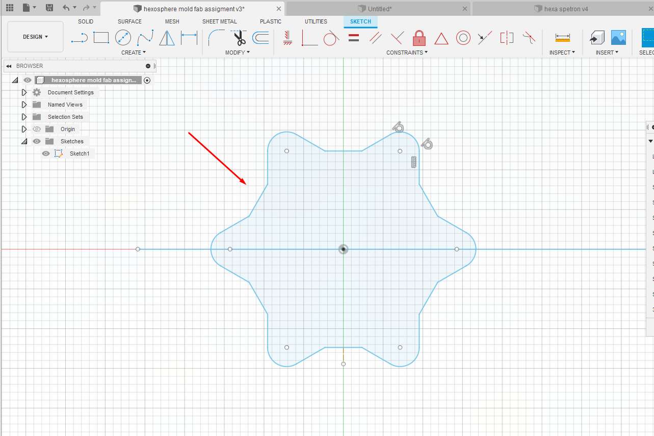
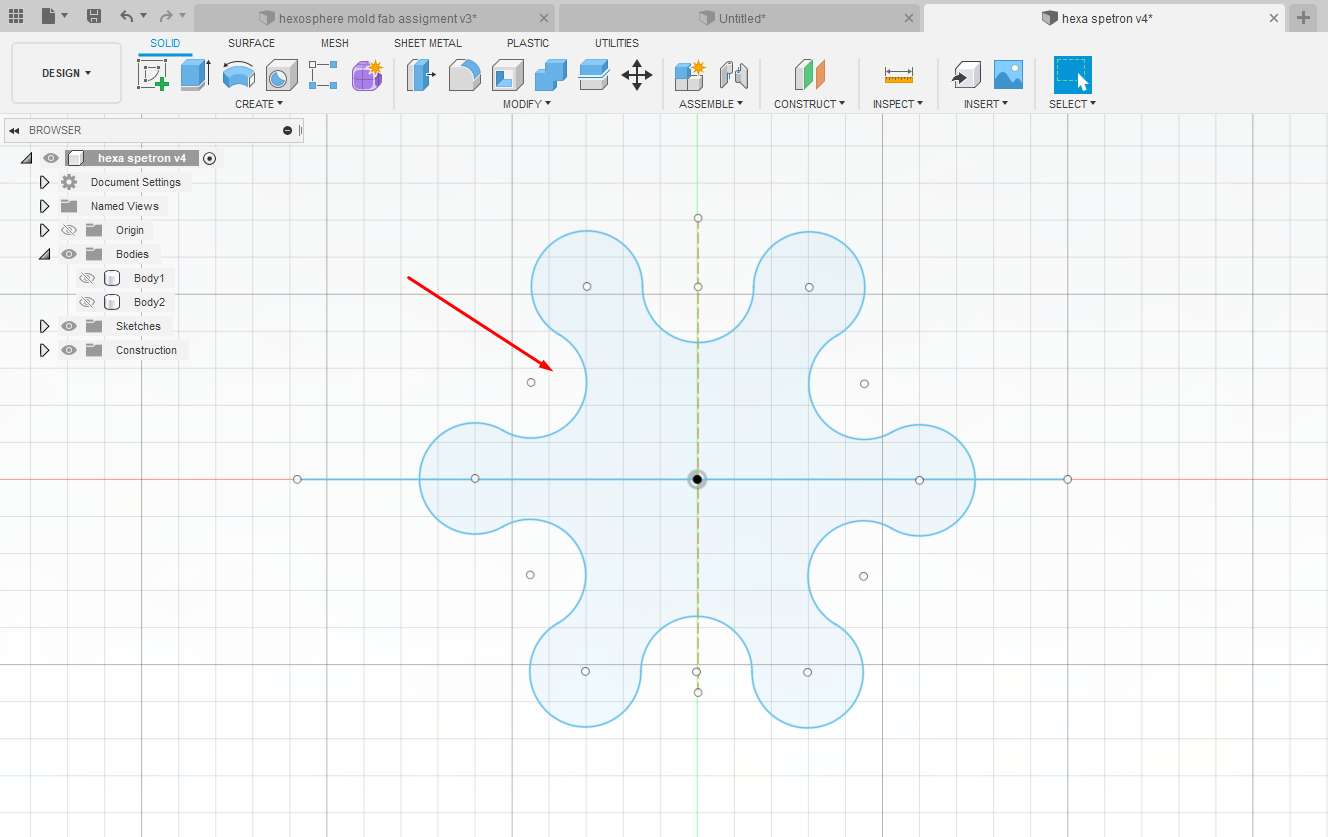
Modified Hexa Sphericons skech in fusion 360.
Modified Hexa Sphericons design in fusion 360.
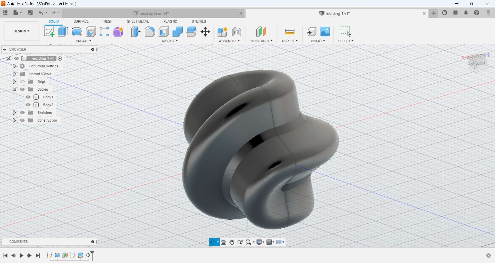
this is how it looks in 3D.
Design negative model for casting:
Considering the shape and size of the job I have to create for my machine I started to make a negative mold design from the modified version of the hexa-sphericon I make in fusion 360. as the wax block I created has dimensions around 200*50*30mm I try to scale down the model and make it in 2 parts with max mold dept considering 18 mm .
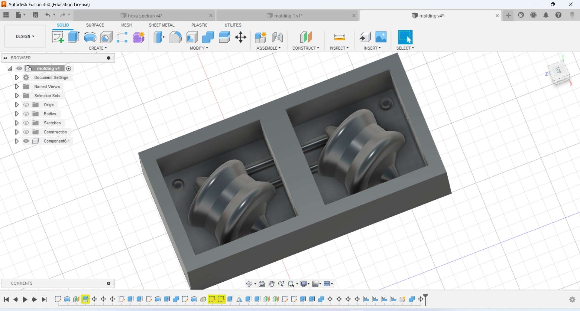
Negative mold designe in fusion 360.
After further Scale down my design limiting to the dimensions I have .I download it in stl format.
Cutting mold with a CNC:
Selection of milling bit:
I use SRM-20 For machining the mold using a ⅛ inches flat end and ball Endmill for machining the wax.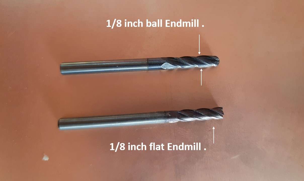
Endmill bit use for making negative mold.
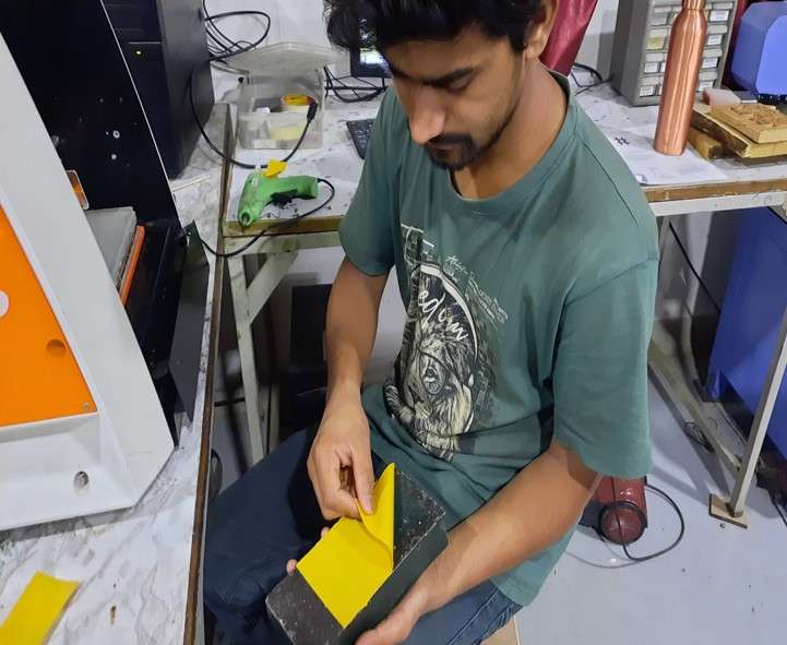
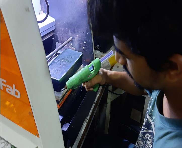
Setting the wax mold on the machine bed:
I use double-sided tape as an adhesive to stick the was block on the machine bed. Further, I add some silicon glue sticks using a glue gun around the edges of the block and bed to make it fit properly.
Generating ToolPath:
For generating the Tool path I use Modela Player 4 which is an integrated software for SRM-20 for milling operation. following are the steps of how I generate the Tool paths for milling machinable was and make them in the shape of the negative mold of design I make for Hexa Sperocon.
The milling process Includes 3 main machining operations respectively.
- Surfacing.
- Rough cut.
- Finishing.
Step1.To start open the Modela Player 4.
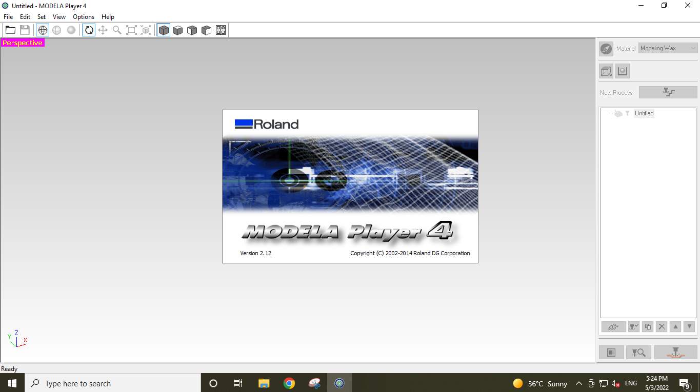
Modela player 4.
Step2.Import the Mold Design. As I mention the file I am using is an STL format file.
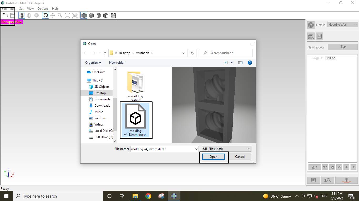
Import the mold stl file.
Step3.Select Machine Type and press ok.
For that go to Toolbar>Files>Select Machine
I select SRM-20 as shown in the image and its parameter as per my machine specification.
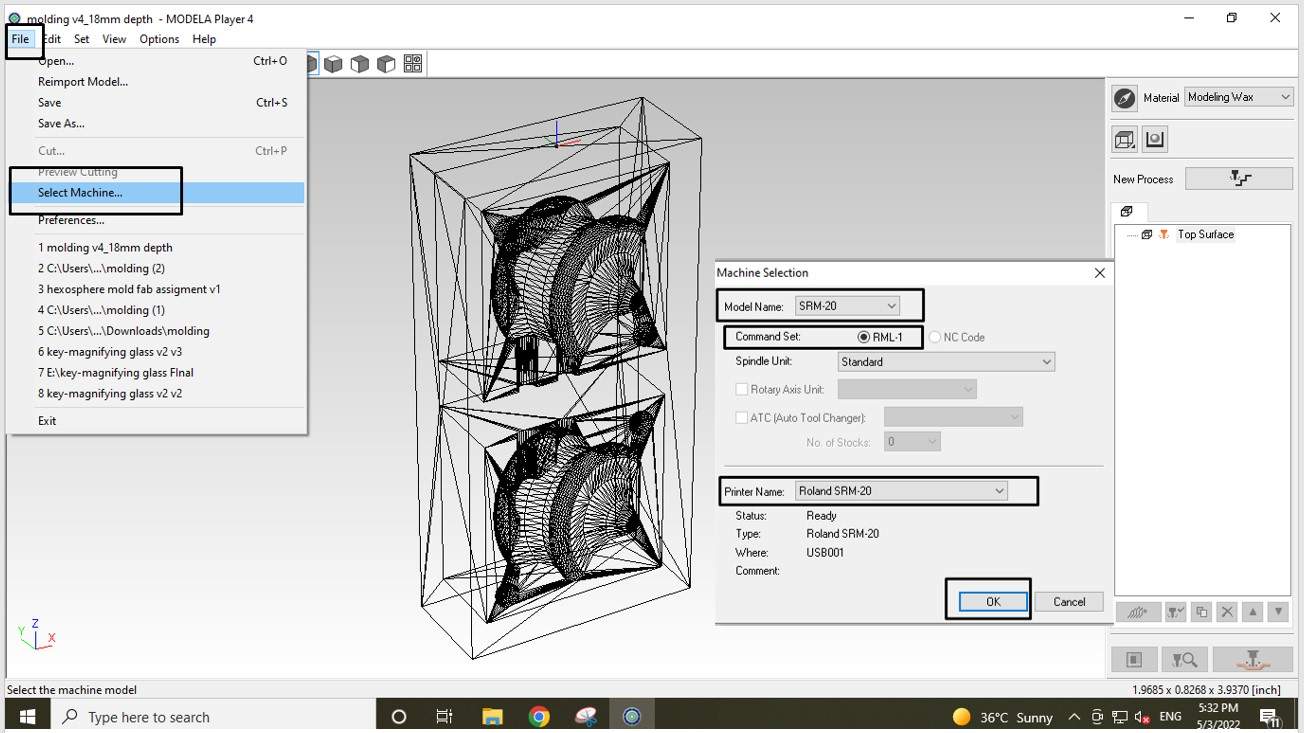
Select machin.
Step4.Then For setting size, Orientation and origin of moulding for machining
I go to Toolbar>Set>Model>Size and orientation
There I select the Top surface side by selecting the top view. I also set the matching origin at the corner of the machining wax block as shown in the image.
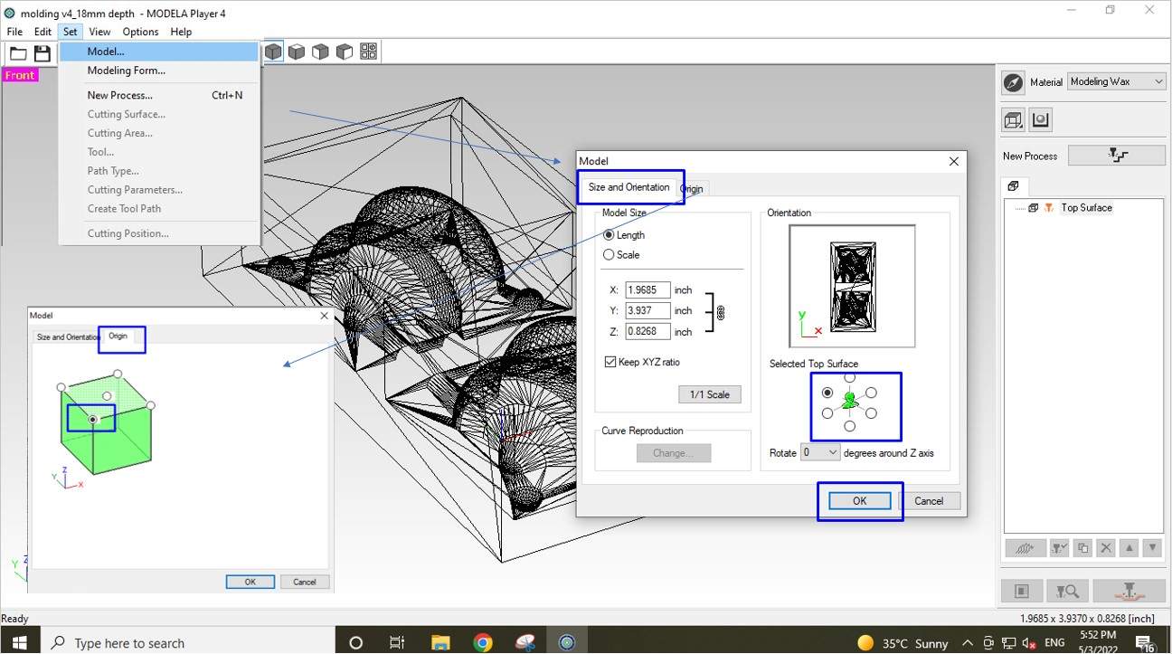
Select orientation and origin.
Step5.Then I select the machining material type as machinable Wax.

Select matterial.
Step6.Now It's time to give 1st cut for an operation which is surfacing. Surfacing is important because the Wax block I am using is not uniform on the surface. It has some slope on it. So if I skip this step it might possible due to inequality in the surface the mold may be cut in nonuniform from the topside.
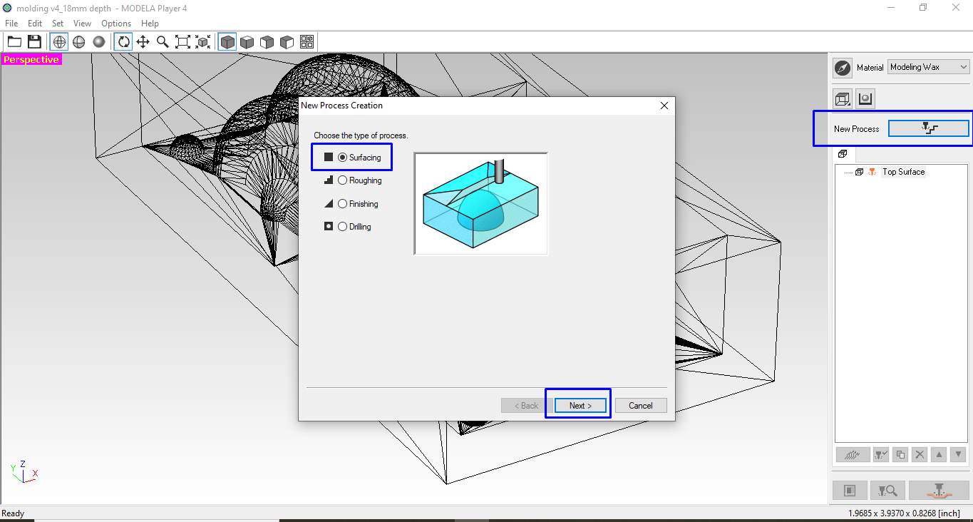
Select surfacing process.
To create a surface toolpath. I click on the new process and click on Surfacing to create a new Processing Path.
Step7.Then I have to select a suitable surface for surfacing. Which is obviously Top along Z-axis. one can also do the surfacing from the side of the block along the X or Y direction. But I find it unnecessary in my case.
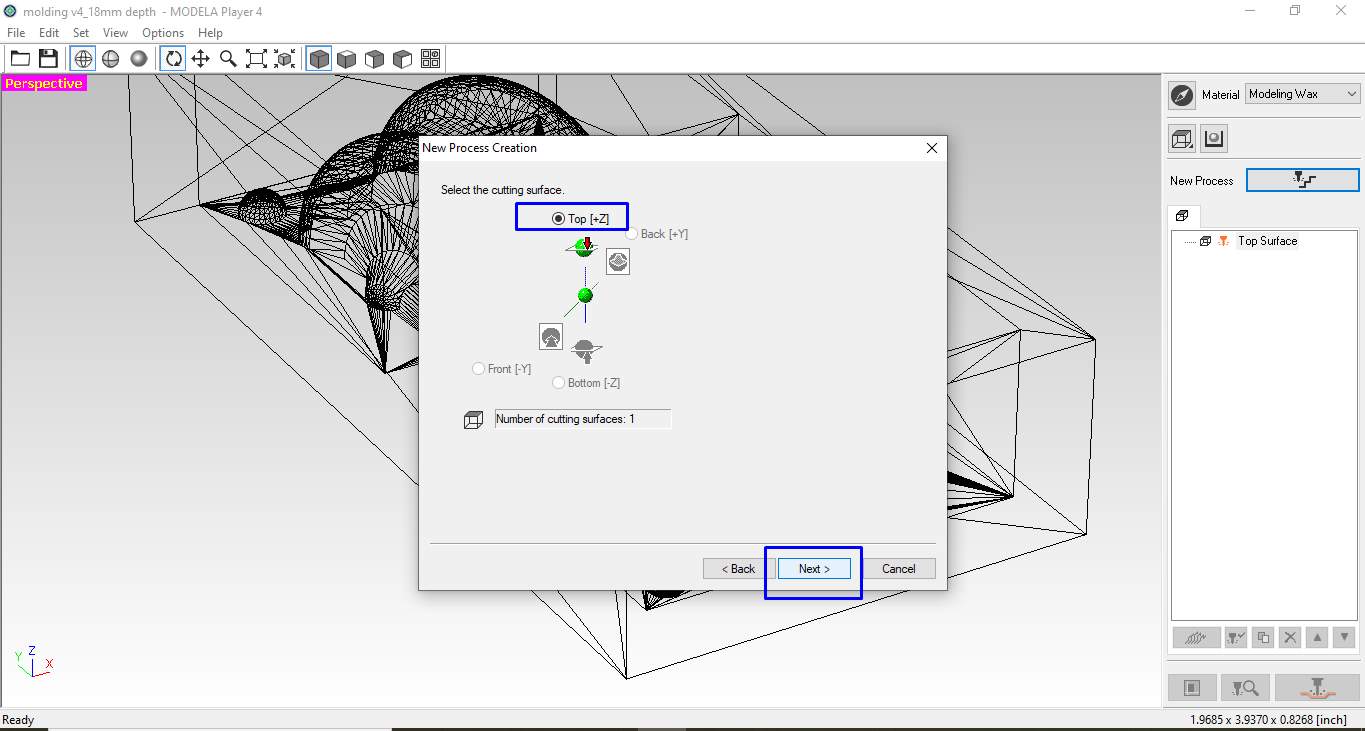
Select cutting surface.
Step8.Then the next step is to set the depth and Area of surfacing.
I modify it as per my requirement by selecting a Specific area for my wax block.
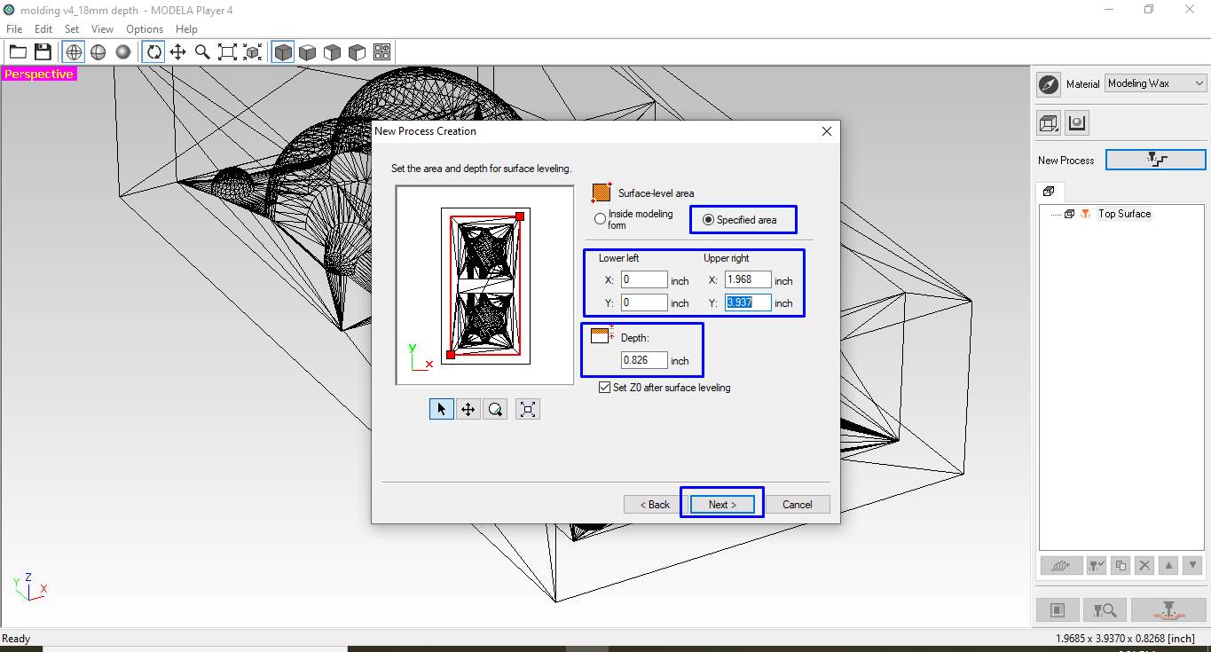
Set area and depth of surfacing process.
The modification I did.
- 1.Upper right X:1.968 inch (50mm)
- 2.Upper right Y:3.937 inch (100mm)
- 3.Depth:0.826 inch (21mm)
Step9. Now in this step, I have to chose the vectors along which the tool move. I chose Y in the state of the X and X-Y options because my primary purpose was just to make a surface plane and also in the Y direction It has traveled a longer 100mm so taking the Y direction will be faster.
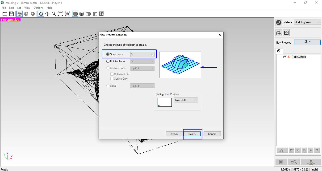
Select type of tool path.
Step10.Now it's time to select the cutting tool. As I have a ⅛ inch flat Endmill. I select the option closer to it which I found 3.15mm Square and keep the settings as default . The challenge in this section was the depth of cut or my mold was larger so I have to make my design scale down according to the depth my tool can travel which I defined in design (18mm).
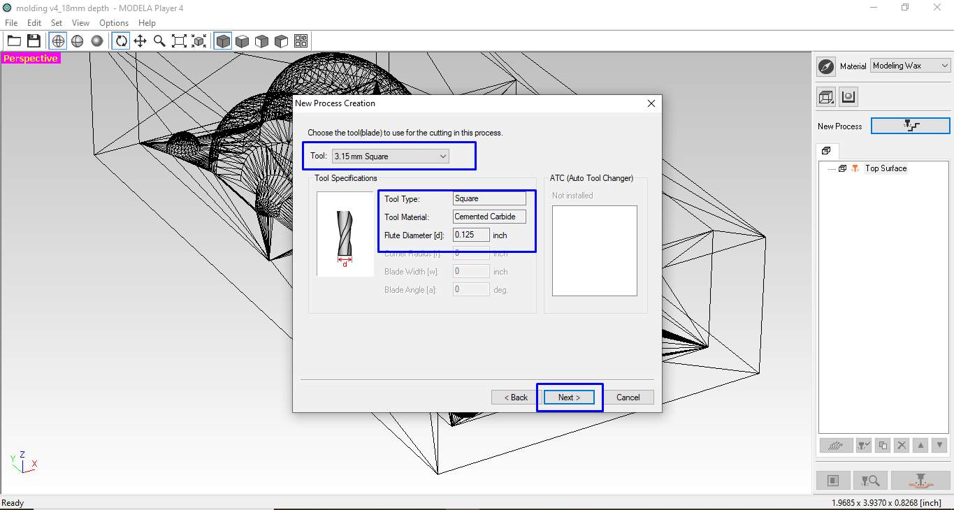
Select cutting tool.
Step 11. This step is where I have to select the cutting parameter. In this step, one can change the cutting amount per tool pass I keep it as it is.
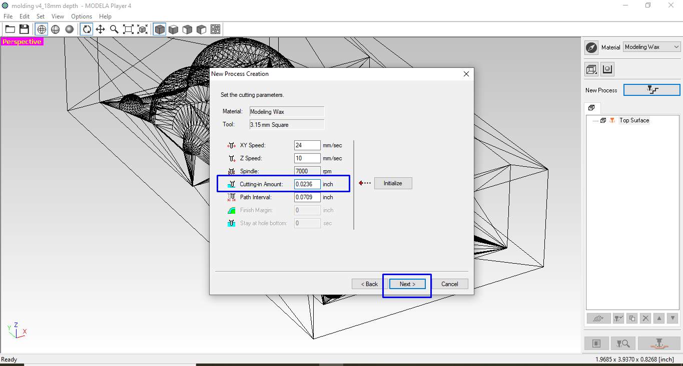
Select cutting parameters.
Step12.Now the tool path is almost created it's time to give its name. Deftly it was already given. I want to generate it on the time so I click on it right now and finish the process.
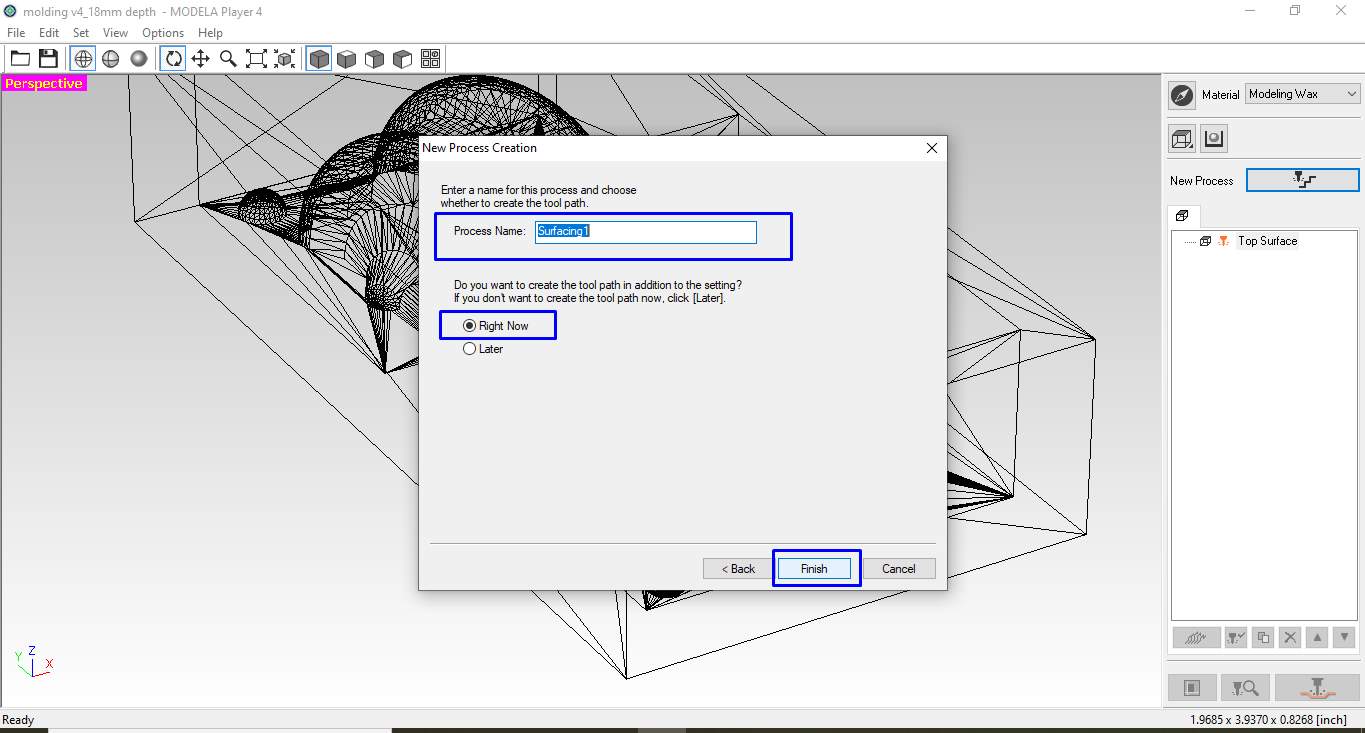
Naming the process.
Step 13. Now I can see the generated tool path graphically. I mention the direction of the tool in the Y axis as you see. A surfacing process file is generated on the left side. I select it and click on the run button at the bottom.
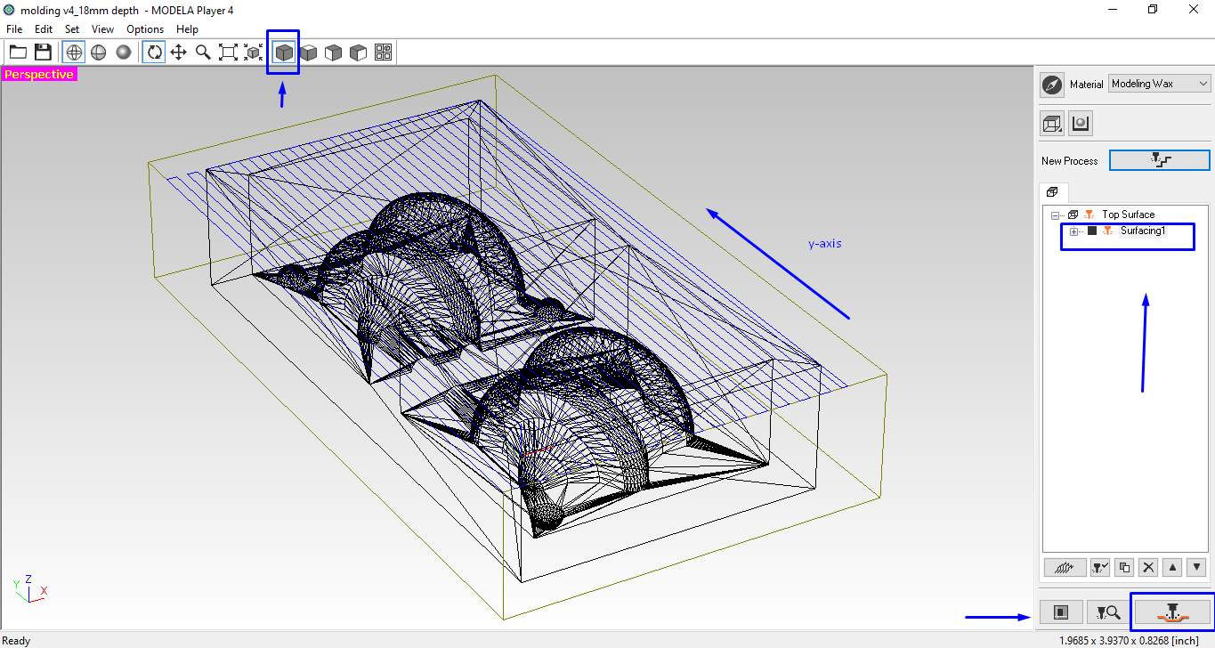
Generated surfacing tool path.
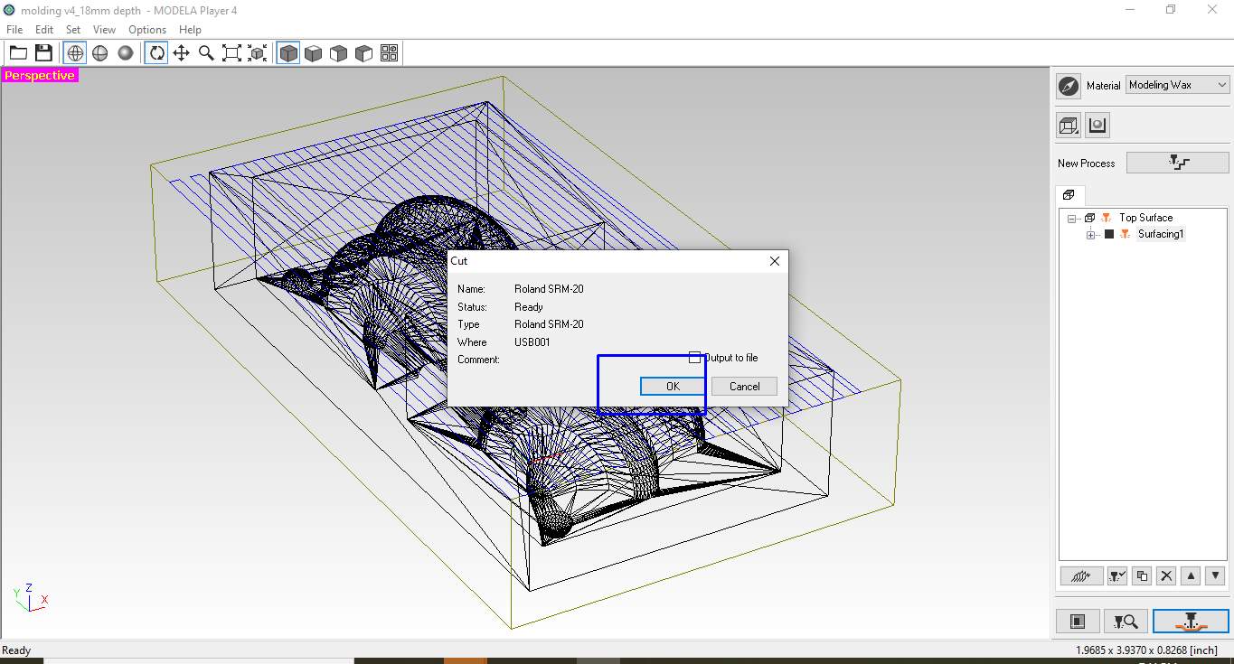
Step14.A window open where you can see the tool path specification I guess I don't take it seriously and click on the button ok button.
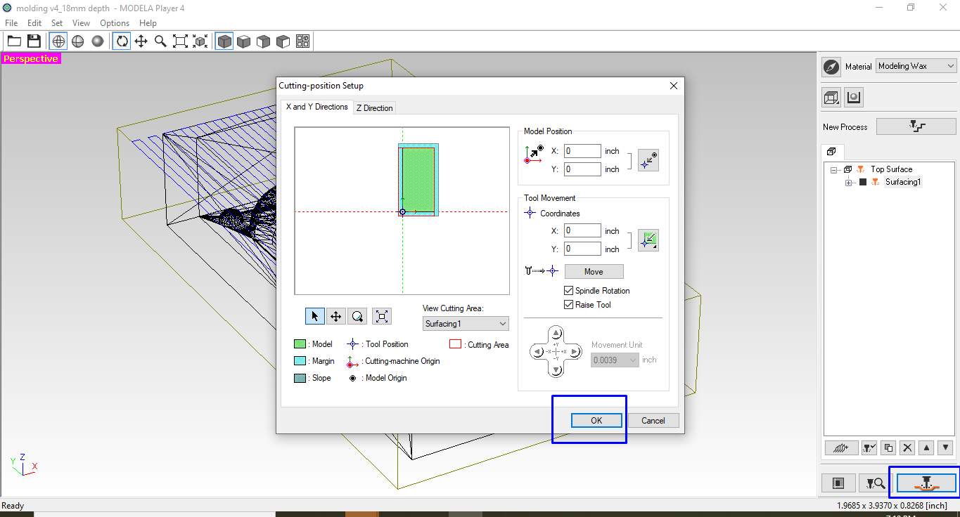
Cutting process setup
Step15.In this step, a window popup asks permission to communicate with the device. I click ok to set communication.
Set communication with device.
Step16.After clicking the ok in the previous step the tool path is ready to run the machine by continuing the process .Before that it is necessary to make the tool on the set origin as per set in toolpath setup . For that, I use V-panal to move the spindle at the corner of the wax block.
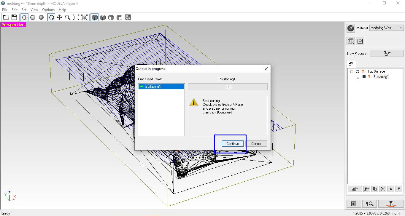
preparing for cutting operations.
Step17.press ok to start the surfacing.
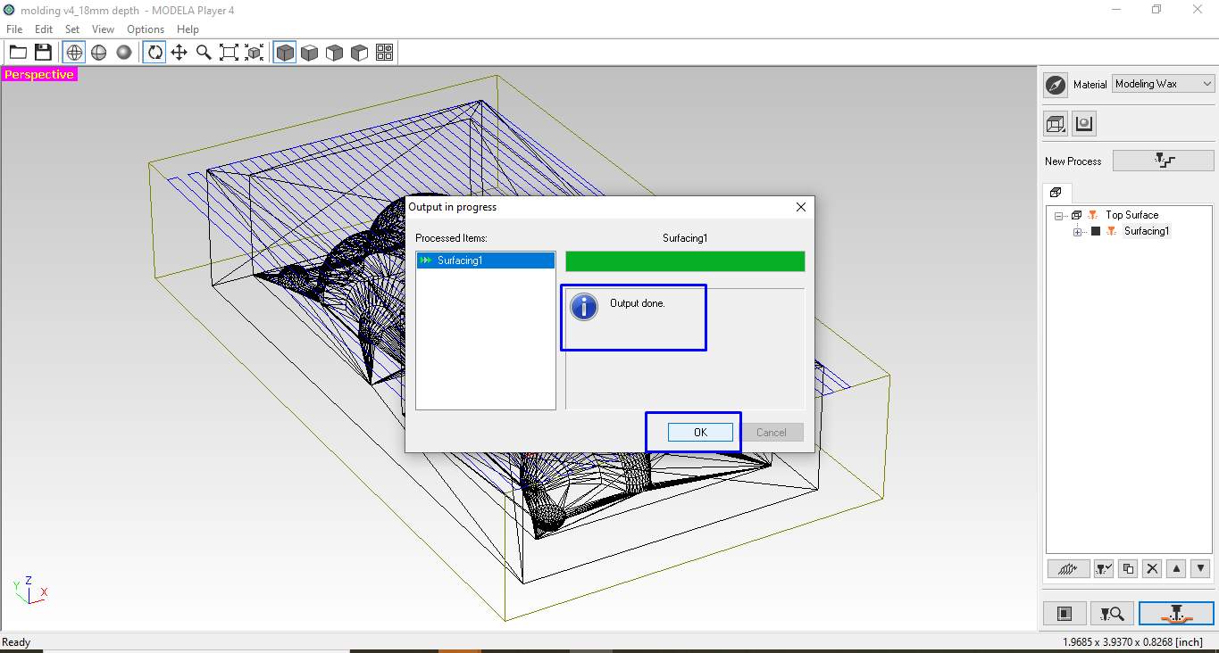
Start Cutting.
This is the finished surfacing on the wax block I am using.
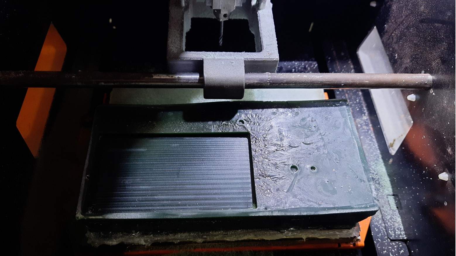
Surfacing on wax.
Step18.Similarly, I give 2nd cut to make mold in its shape .which is a rough cut.The rough cut is given before the finish cut to remove the maximizing material on the machining job and its main objective is to make the object in its shape not necessarily exact, to make a fast machining operation.
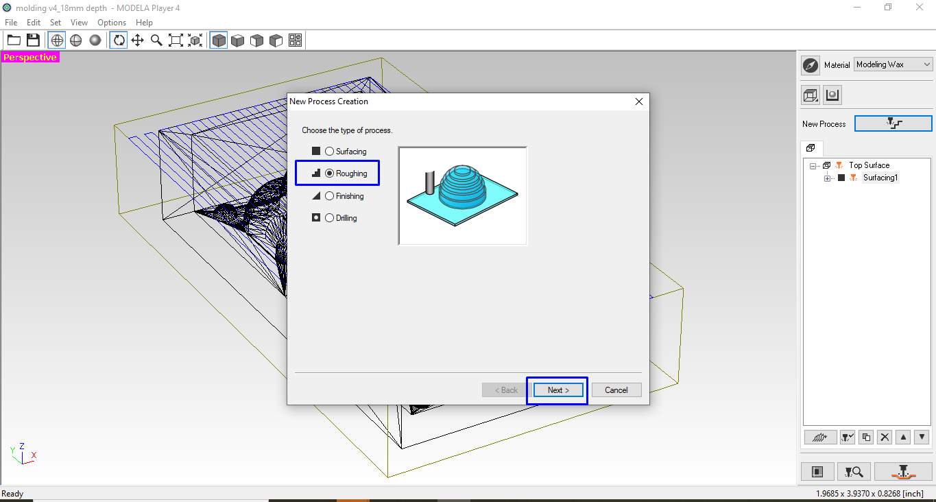
Sellect Rough process.
To create a rough toolpath. I click on the new process and click on rough to create a new Processing Path. I follow the same procedure and the same parameters as I am using the same flat Endmill bit for rough-cut too.
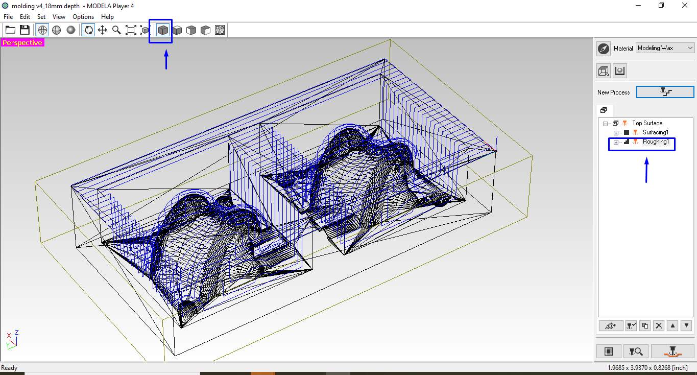
Generated Rough tool path.
Don't forget to make the tool z-axis origin set on the newly finished surface by using the gravity method using the V-panal setting. I keep the X-Y origin as it is. Because I have defined it already in my tool path.
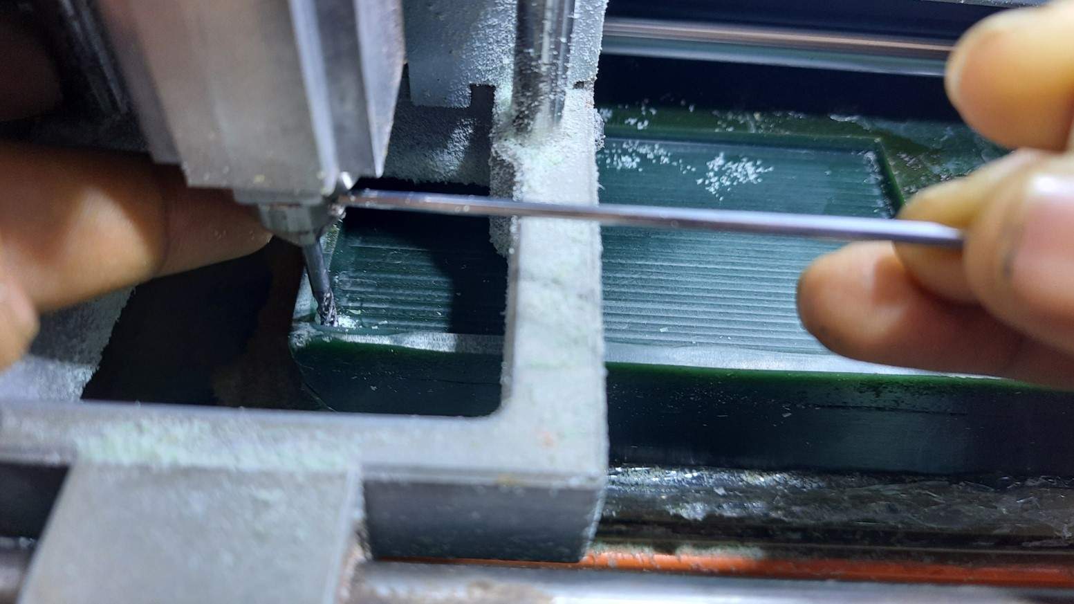
Gravity tool befor giving rough cut.
This is the finished machine rough cut using a 3mm flat square endmill bit.
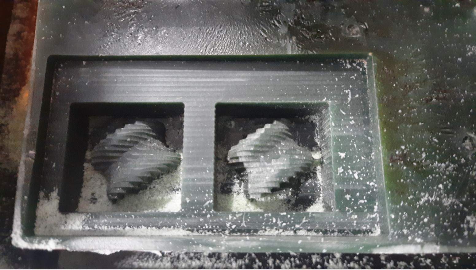
Rough milling on wax.
Step19.At the last ,I give 3rd cut that is finish cut .Objective of finish pass is to improve surface finish, dimensional accuracy and tolerance.It take much more time tan all the process .
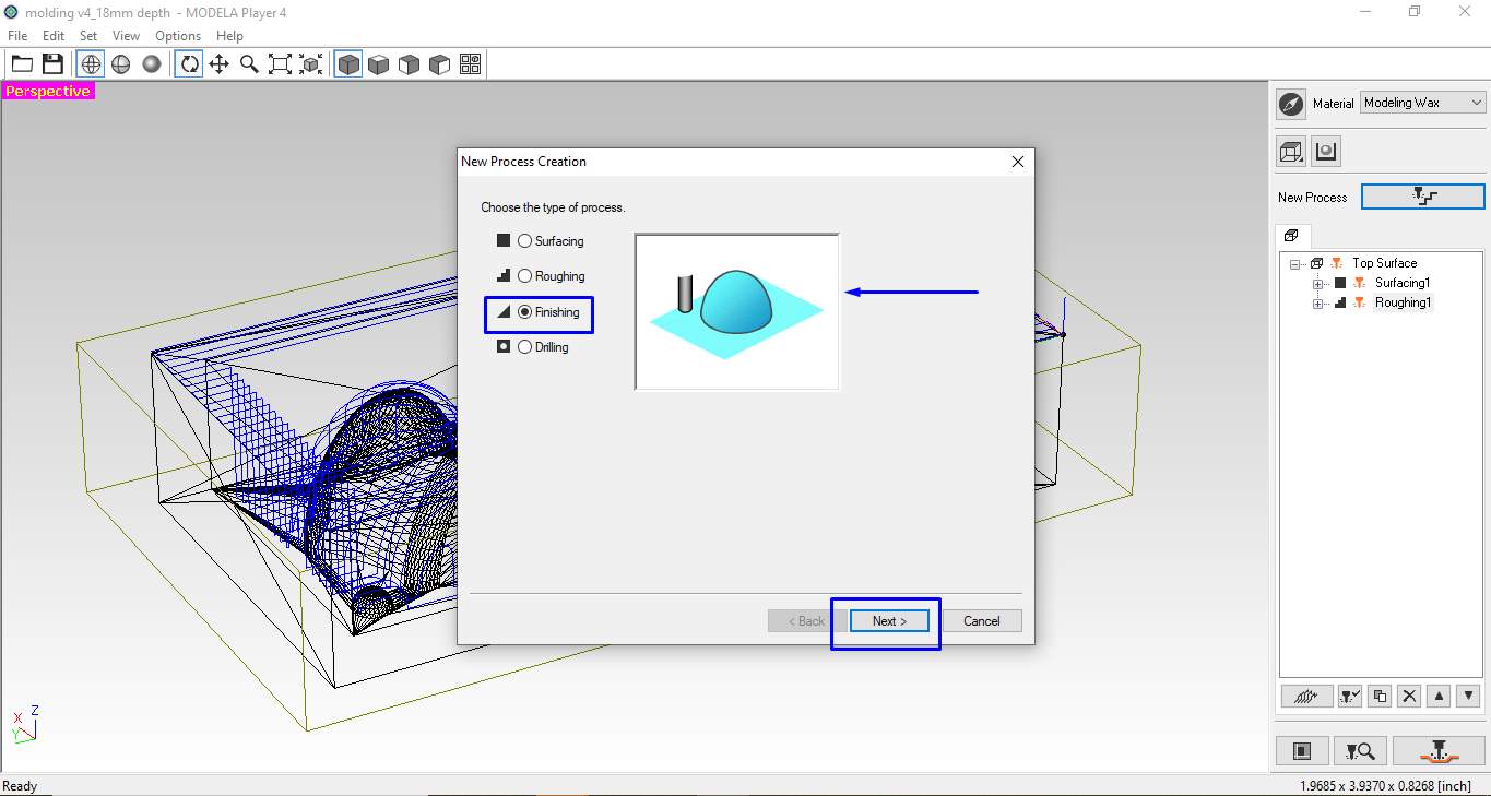
Select Finishing process.
For making the finish cut I fallow the Same process as per done for above processes.
Note that for finish cut I use the same origin setup as in Rough cut there is no need of shifting the Z-axis.
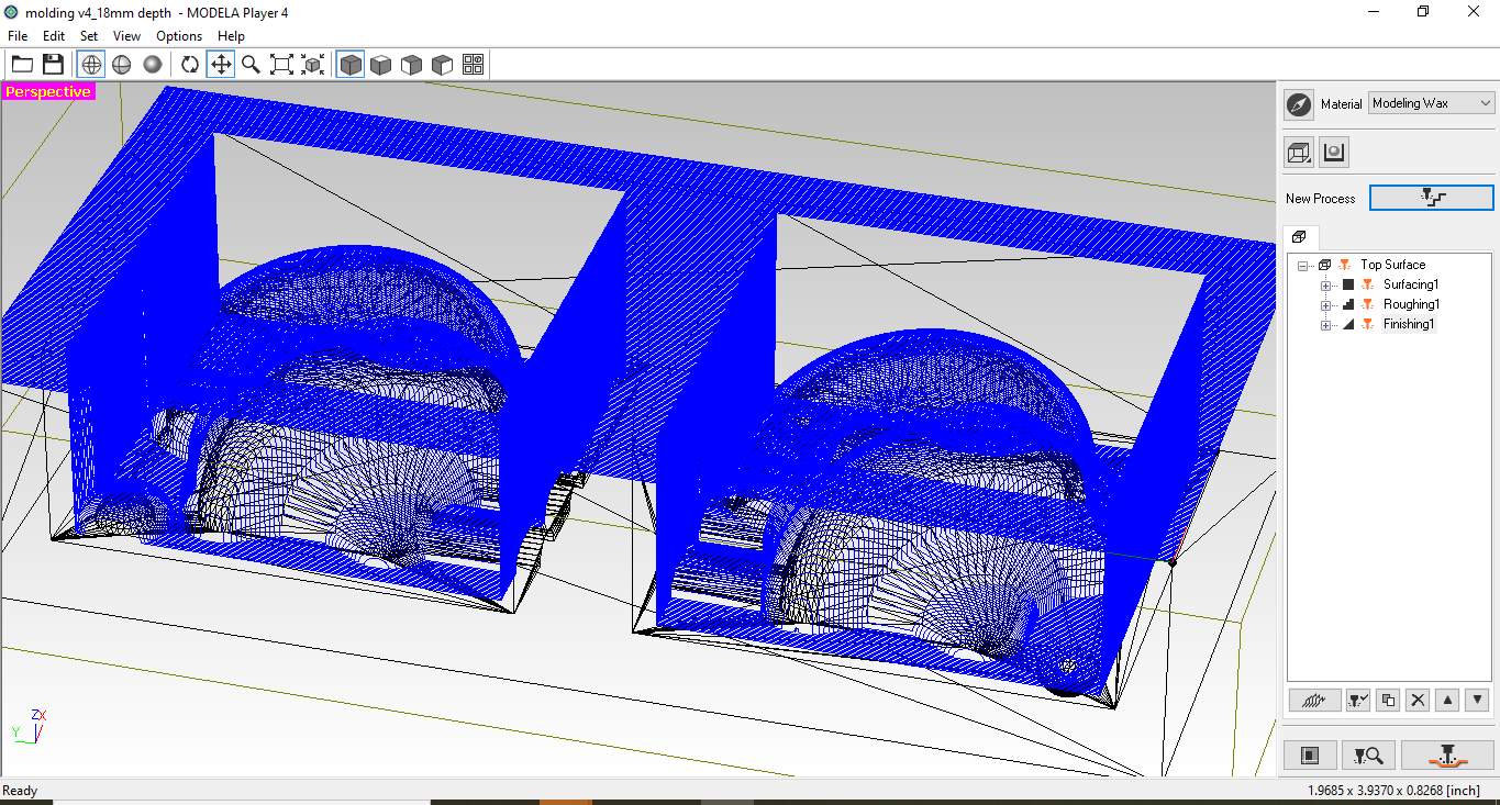
Generated Finish toolpath.
This is the final fully machined negitive mold .I need to clean It .in order to use it for casting a positive mold.
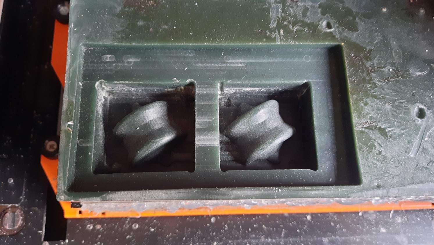
Final finish cut on wax.
I remove all the excess chips and dust on the mold using a brush and clean it with water and here you can see the mold is ready for casting.
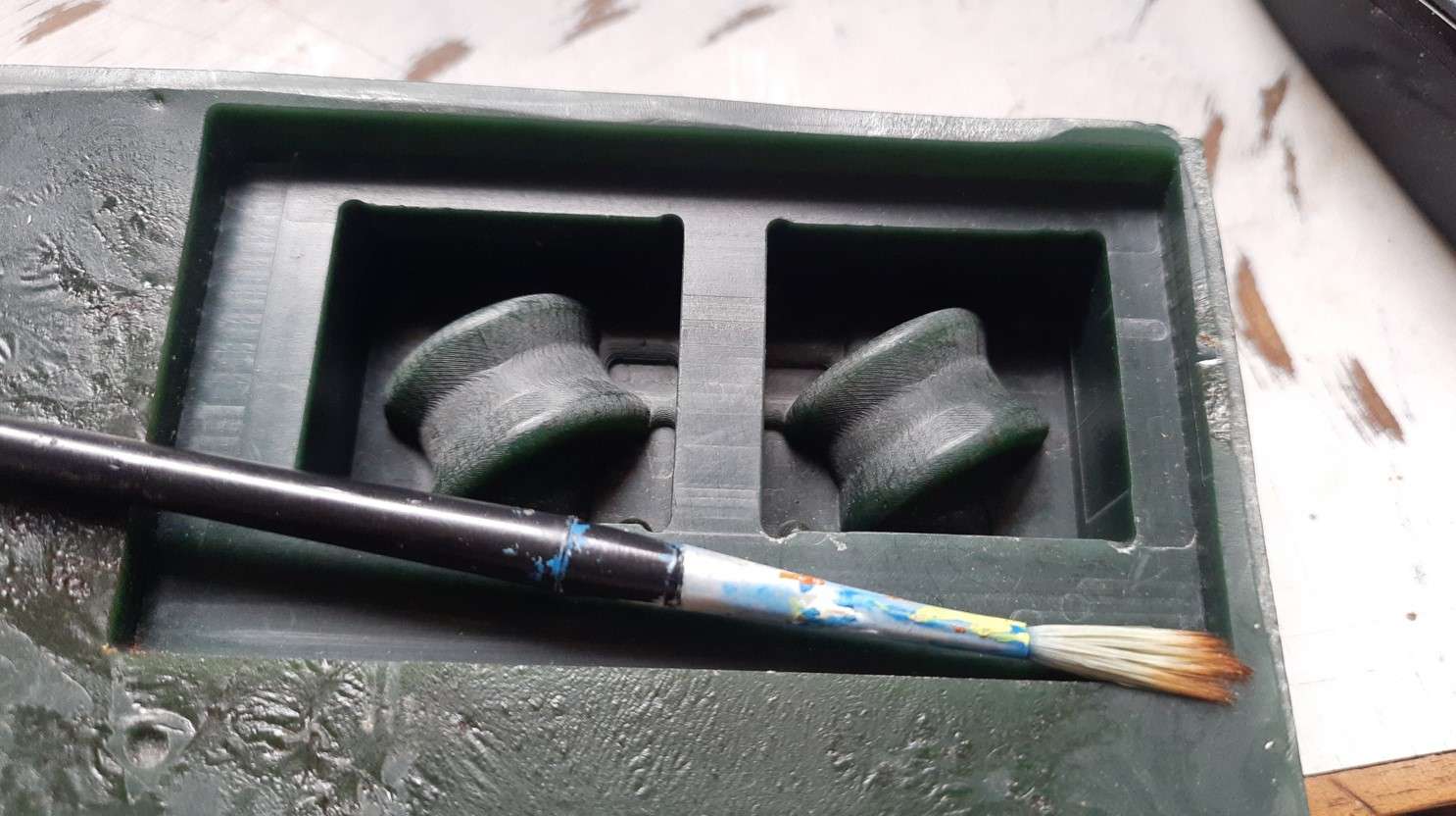
Hexa-spericon negative Mold .
Making Positive mold:
Finding volume of Positive mold:
Positive mold is the mold we use for casting the object .In fab academy we use mainly silicon as a material to make it. for making a positive mold . I need to calculate the amount of silicon I require to make the mold.I don't know how to calculate it in fusion 360.rather I haven't tried and I use the simplest path to measure. I pour the water in a negative mold and calculate the volume of water per negative mold required to fill it. which I found around 45ml.for making such molds I will require 45+45=90ml of silicon solution.
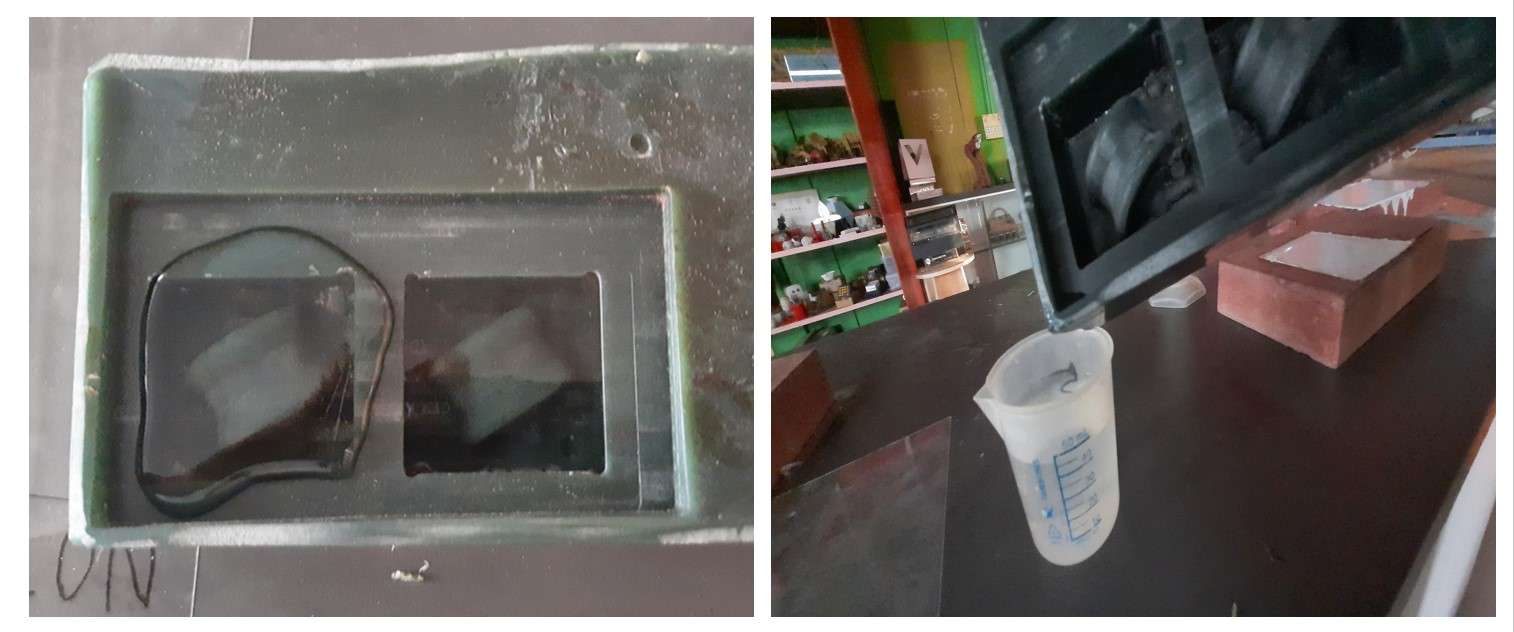
measering infill volum using water volum.
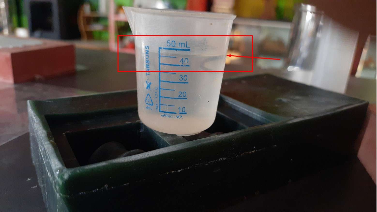
Measering infill volum using water.
For deciding the amount of silicon (Part A and Part B ratio) I use this Excel sheet.which I redesign referring the Excel sheet created by Kishor sir .
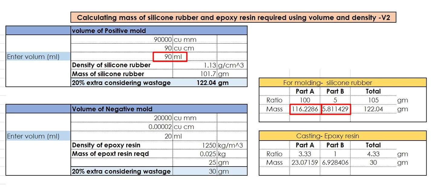
Silicon propertion calculater .
By using this proportion I make solution of slicon to make the positive mold .I measure them using a weight measuring machine in our lab and mix it in above ratio .Try to avoid the bubbles in it.
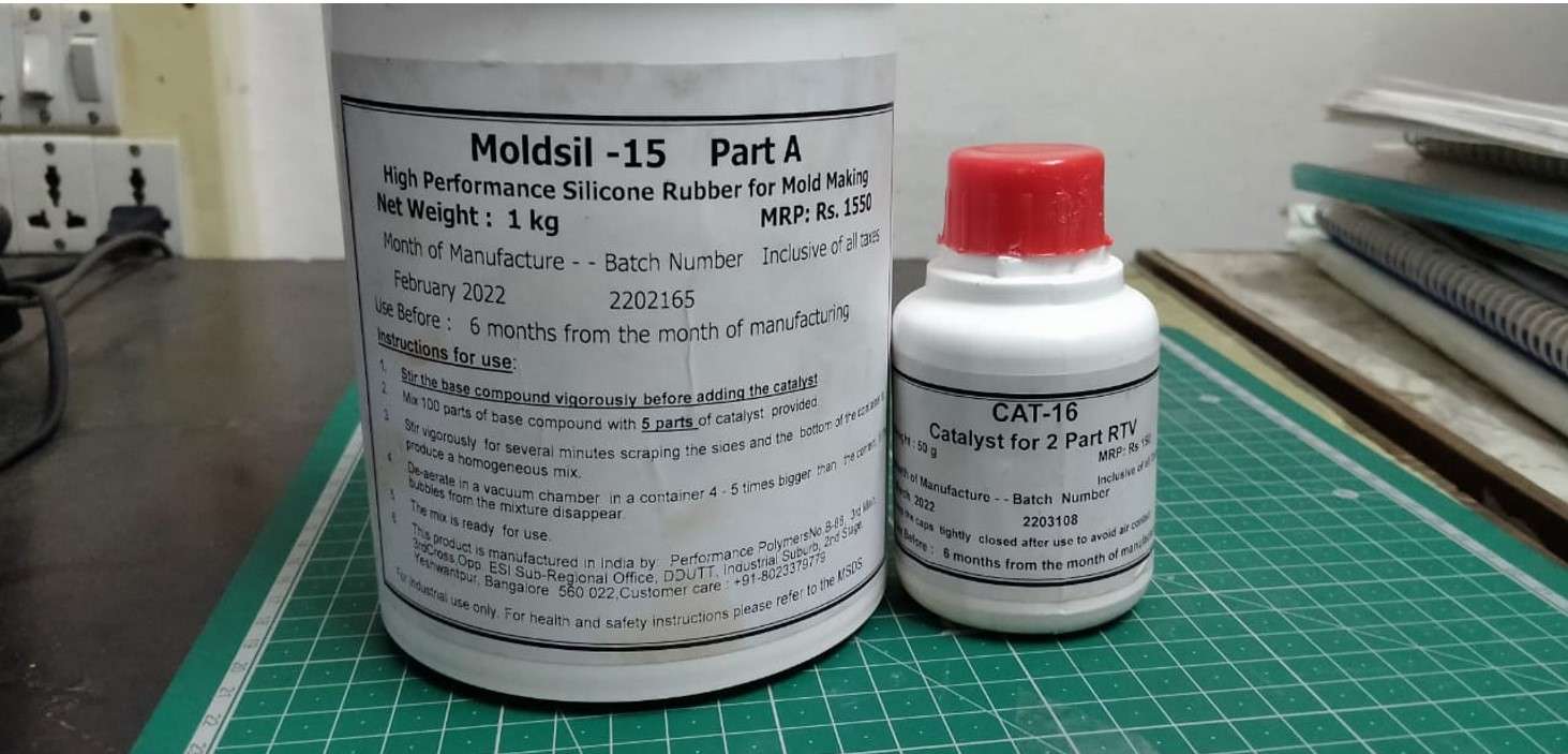
silicon .
Then I fill the negative mold with this silicon and leave it to settle down.
making Positive silicon molds.
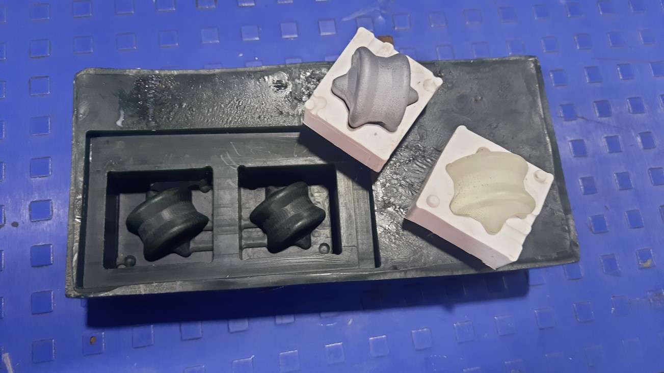
These are the nicely made Positive mold of Hexa-spherion I got .In my first attempt itself.
silicon molds.
Casting Hexa-sepeicon:
Here I come very close to making my cast Hexa Spericons .I use Epoxy resins as a casting material .
Epoxy resin .
I follow the same method to measure the volume of positive which i did with the wax mold.now for mesering Casted part volume I make use of silicon positive mold and use water to find the infill volume init.
Epoxy resin propertion calculater.
After making the Epoxy solution in refer to calculated ratio. I also added some amount of silver oil paint color in my casting solution to make it color full.

making Epoxy resin solution.
I hold the mold parts in between the clamp and also add tep on them to avoid
leakage.I take all the precautions while pouring the solution.
Note that Epoxy resin left stain back if it remains on flower
.
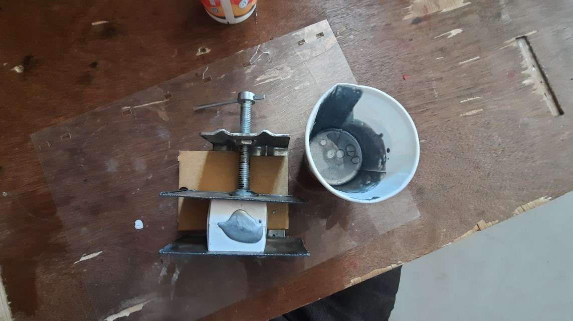
Casting of Hexa-spericon.
Error in casting Hexa spericon:
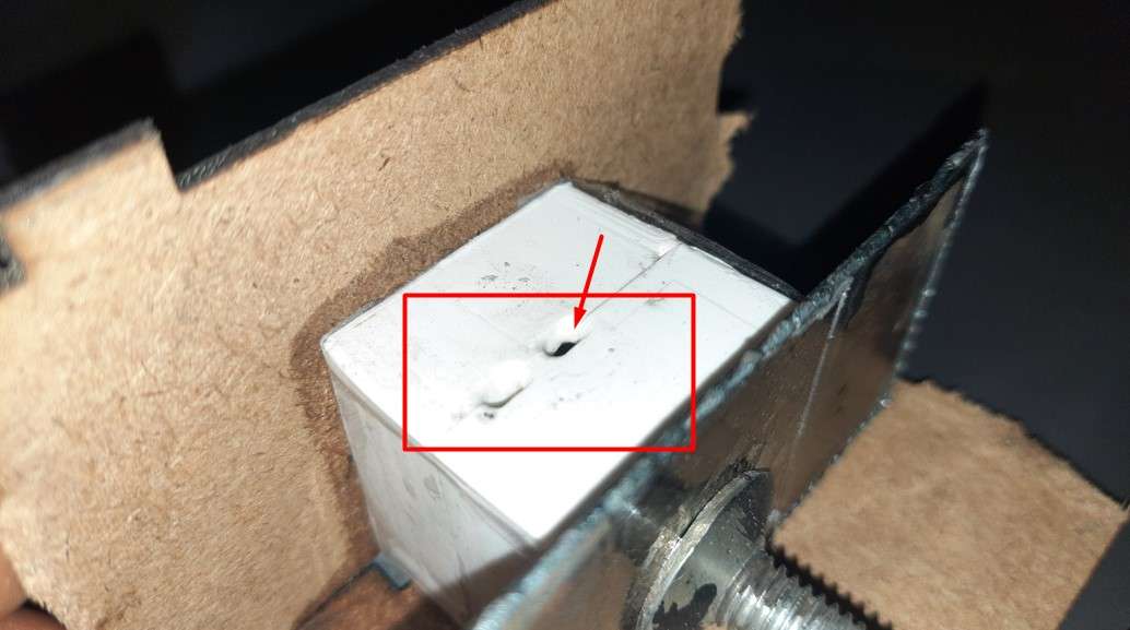
I got a bubble In my casted part.I fallowed all the majour tips while casting like not to catch the bubble in casting while pouring the solutionin silicon mold and also take care while Mixing the solution in such a way to not catch a bubble. Also I fill the mold very gently to avoid any kind of bubbling.Eventhough it happen.And it happened at the inlet of fold from where we pour the solution.as shown in image below.
bubble In casted part.
2st attamp of casting Hexa spericon:
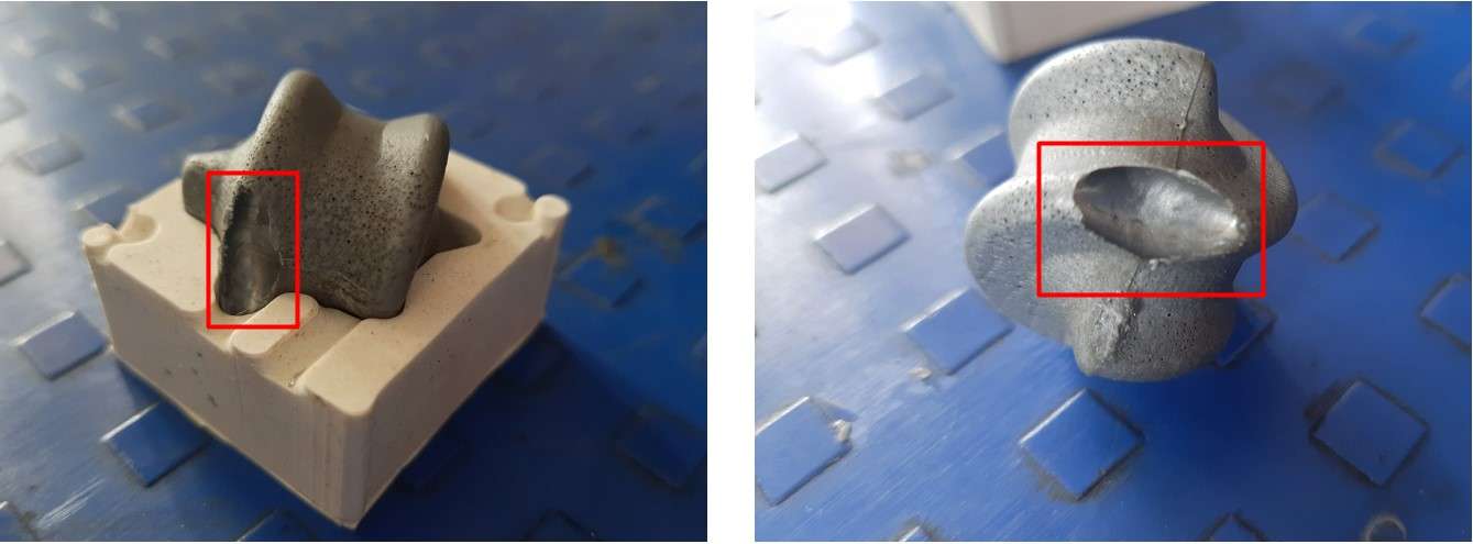
At this attempt I decided not to add the silver oil paint and do as I did in my 1st trial .but this time I make a close look on the mold.I observe that after a certain hours (~6-8) the Epoxy resin got shrink down making the cavity at the inlet pour cup empty .It might because sprue (inlet pipe)of my mold design is too short . or another reason might be licking but I use a tep to sill it from the outer side.whatever be the reason. So far for that I decided to fill in once agen and its work.
cavity at the inlet pour due to shrinking Eposy resin.
It works and I end up with geting a nicely casted Hexa spericon.
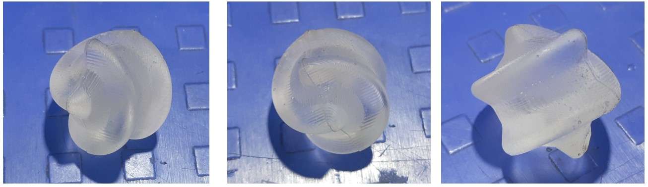
Casted Hexa-spericon.
Heroshorts of this week:
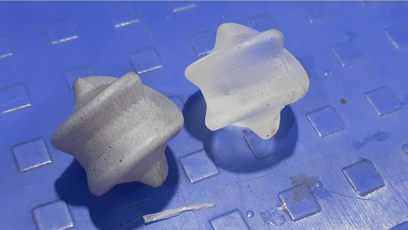
Casted Hexaspericons.
All I make this week in one image