The task list for this week:
- Group assignment:
- Complete your lab’s safety training.
- Test runout, alignment, speeds, feeds, and toolpaths for your machine.
- Document your work to the group work page and reflect on your individual page what you learned.
- Individual assignments.
- Make (design+mill+assemble) something big.
Group assignment:
We don't have CNC router machine in our lab So we all have to travel outside to pune city at COEP lab to complete our this assignment.
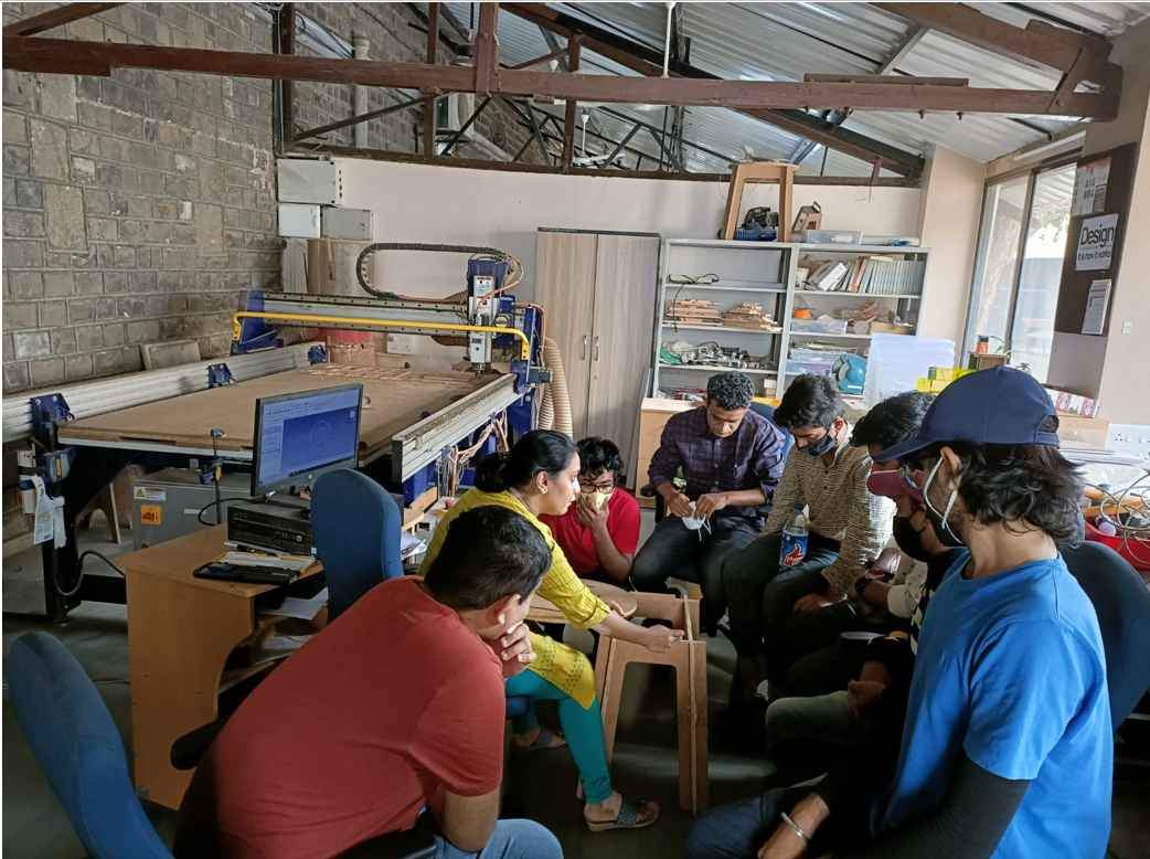
Group assigment discussion at COEP.
.It was fun to travel after long time and visit other lab and meet new people there.
ShopBot CNC Router :
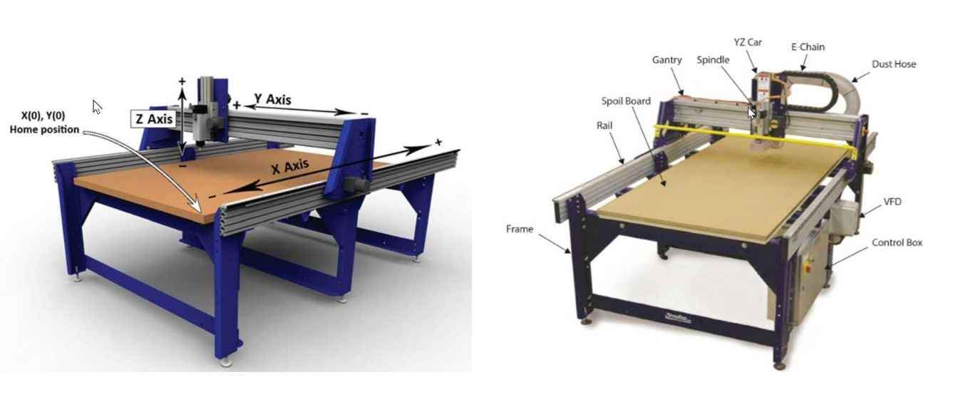
ShopBot CNC Router.
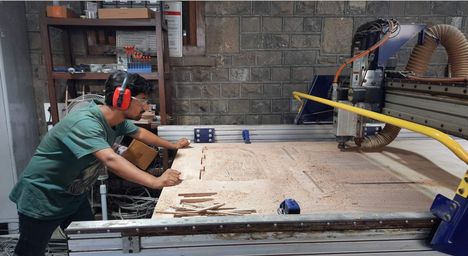
This week we use another amazing CNC machine ShopBot PRS Alpha . The ShopBot PRS Alpha is a CNC routing machine that allows users to cut, drill, carve and machine wood, plastic, aluminium and other materials 3 axes, X, Y, & Z, For this week to make something big we are using this machine to make a soldering Table for our lab.
The specifications of the printer are as follows:
- Table Cutting Dimensions: 69 inches x 96 inches.
- Table Area: 6624 square inches = 46 square feet.
- Table Thickness: ¾” Plywood Bottom Layer, ¾” MDF Top Laye.
Safety Precautions.
a. ShopBot SafetySHALL..
- You SHALL notify SpaceShop staff prior to running any job.
- You SHALL wear ear protection.
- You SHALL wear closed-toe shoes at all times.
- You SHALL wear eye protection when working with tools and processes that involve chemicals, metal shards, wood chips or sawdust.
- You SHALL clean up your space after every job session, and leave 10-15 minutes for cleanup prior to shop closure.
- You SHALL secure badge and any loose items that might get caught in moving machinery.
- You SHALL make small cuts at slow speed otherwise you will risk breaking the cutting tool, and ruining your material.
- You SHALL hold the ShopBot Dongle(contains ESTOP,RESET, START buttons) in your hand, during the entire operation of the ShopBot, for quick access to the ESTOP in case of emergency.
- You SHALL always be ready to react in case an operation fails.
- You SHALL make sure the spindle collet and cover nut are properly secured and not over-tightened.
- You SHALL always use a sacrificial layer under the material you are cutting, so as not to cut into the table below.
- You SHALL ensure the End Mill is fastened securely inside the spindle collet, before starting your operation.
- You SHALL ensure all tools are in good condition before use.
- You SHALL use your sense of sight and sound to keep yourself aware of the operational conditions of the ShopBot for safe use.
SHALL NOT..
- You SHALL NOT leave a machine unattended while in operation.
- You SHALL NOT touch materials and chips being cut since they can be hot.
- You SHALL NOT wear or have any loose objects on your body while operating this machine, including badges, jewelry, loose clothing, and loose long hair.
- You SHALL NOT work alone while in the SpaceShop.
Read more About group assigment .
Individual assignments:
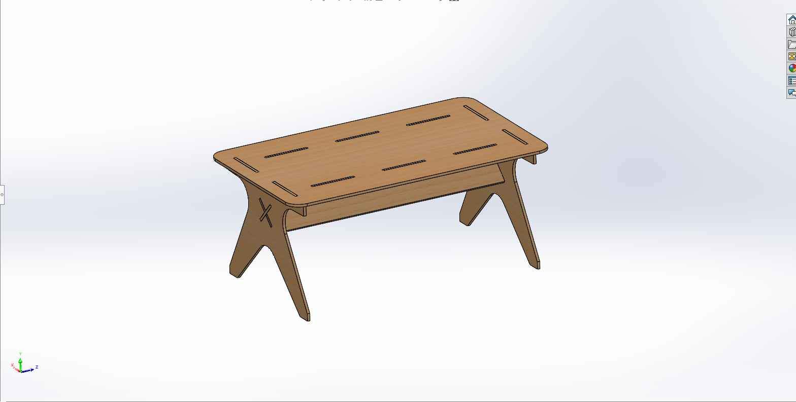
For this week I decided to work on making a Soldering Table for our Fab lab ,As I was thinking to make something which involve in regular use . For making it creative I try to designe it outside the usual regular table design we have in our lab.So I start designing it as following.Designe:
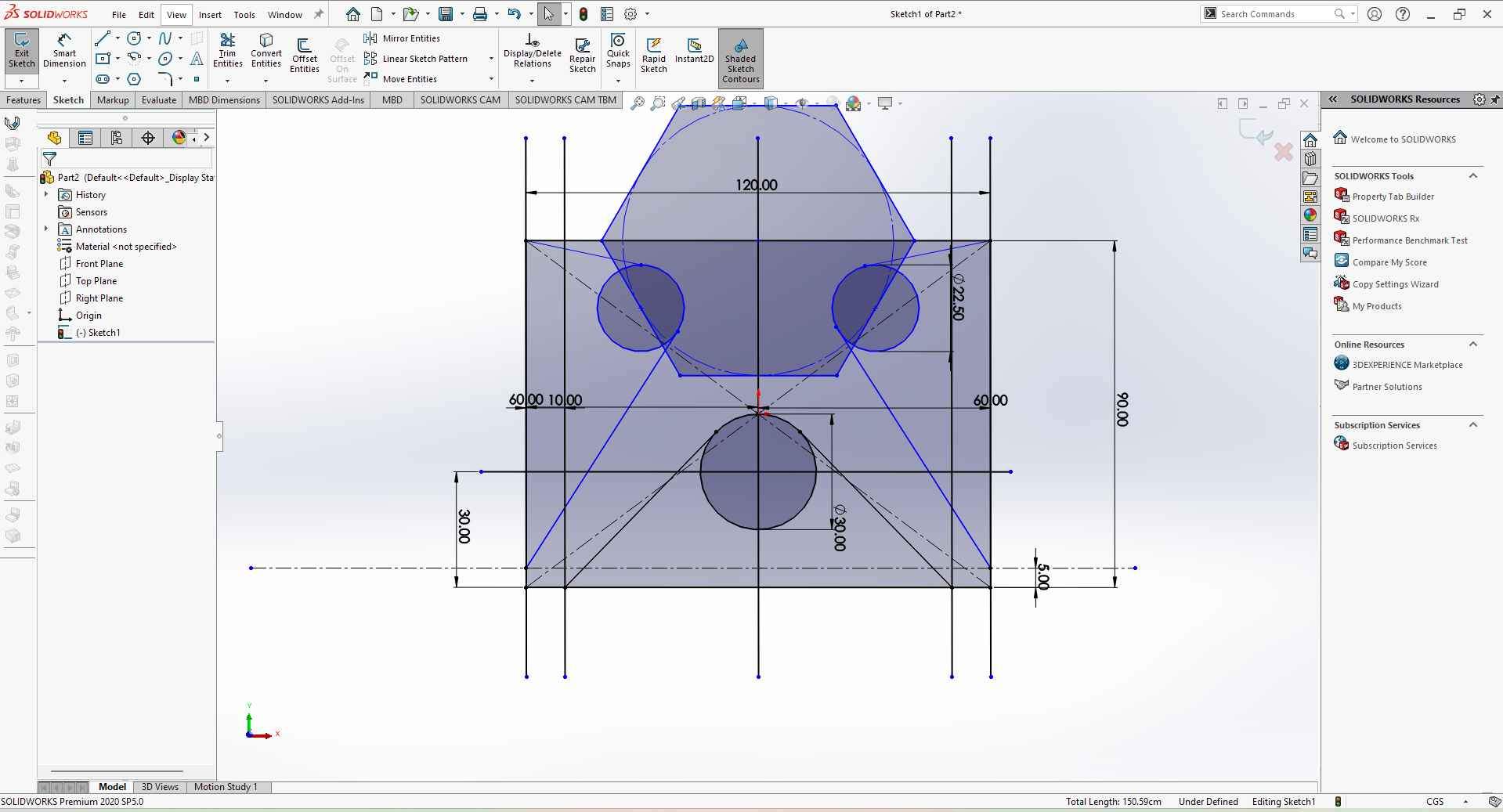
This week I decided to design my table in SolidWorks CAD software .I first try with fusion then I shifted to SolidWorks and stick to it. The design must be Parametric one ,In case I have to change the dimensions it will be an easy task for me during machining .Part Drawing:
This are the parts of Soldering table I design in solid works.
Side Legs SupportI start with drawing simpler designs but then I think to make something good so I try some designs. If you read my laser cutting assignment then you must be familiar with the staring shape I create for a press fit. Inspired by that design I make a Table design which ends like the one you see below.
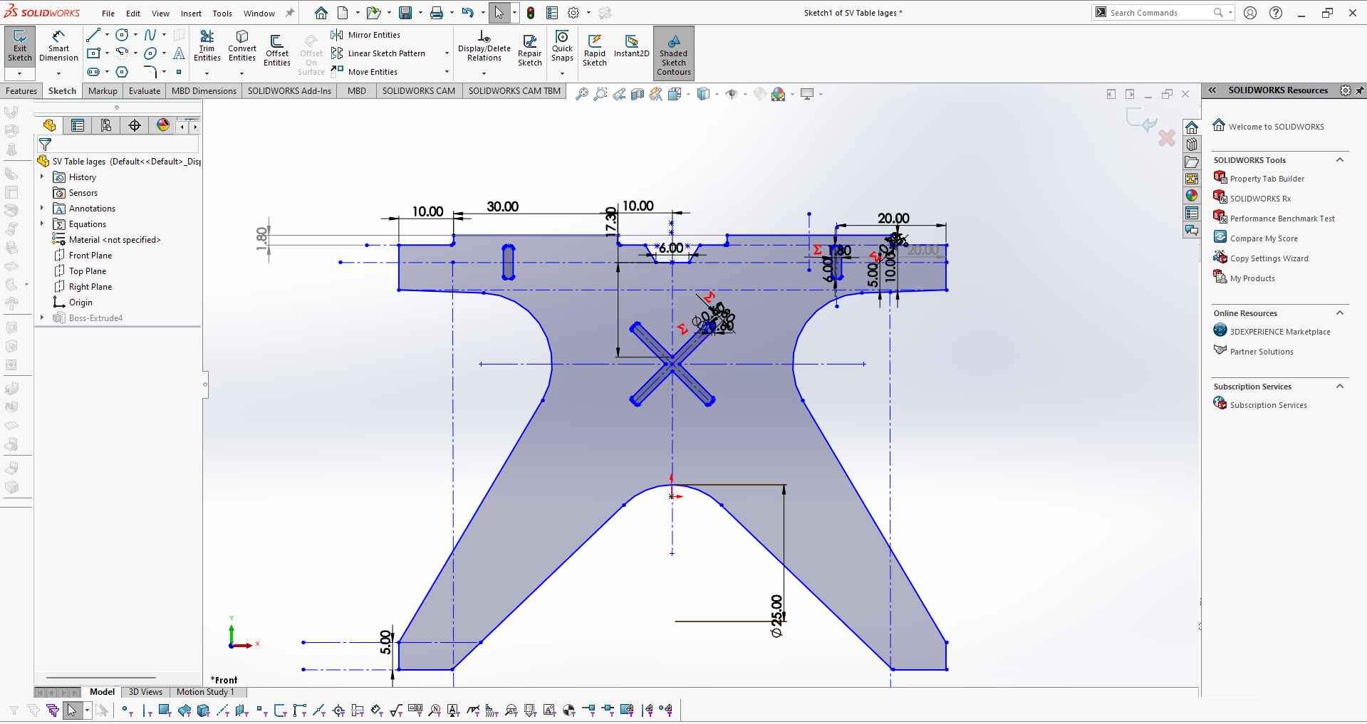
I also added a cross X type pocket to make the CG down and also to make an attachment between two legs plates.
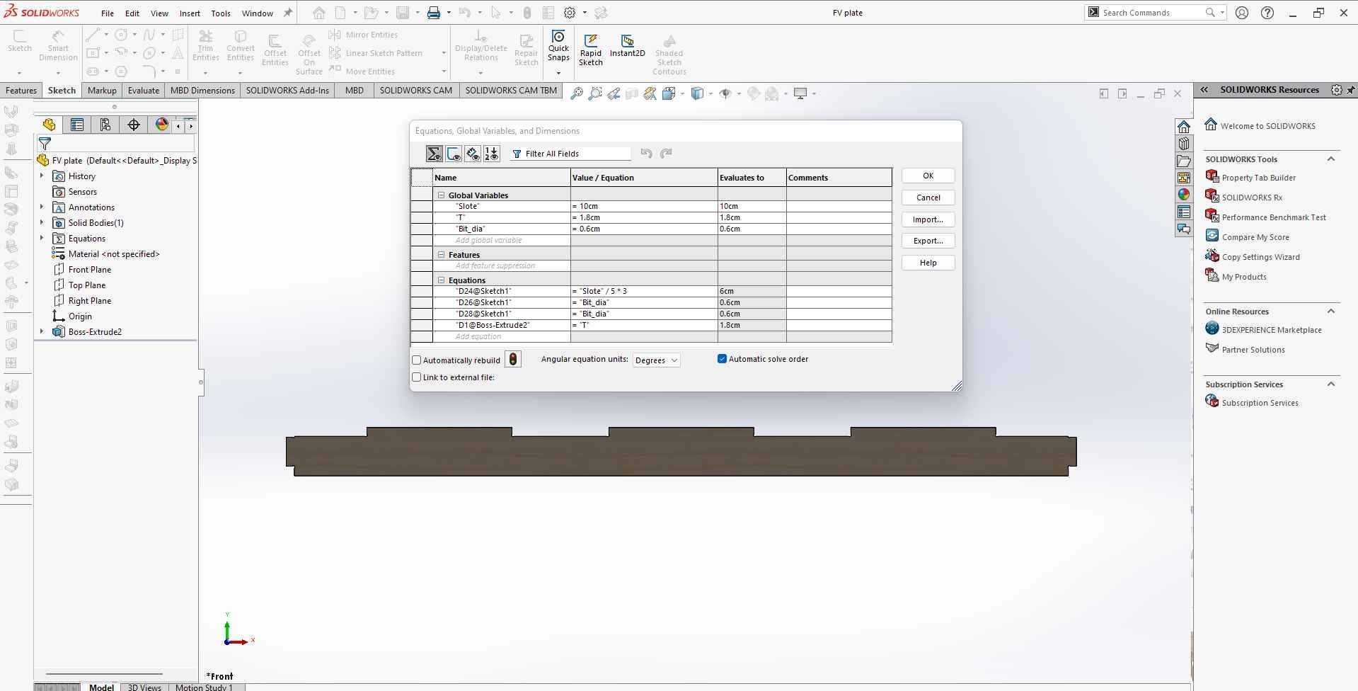
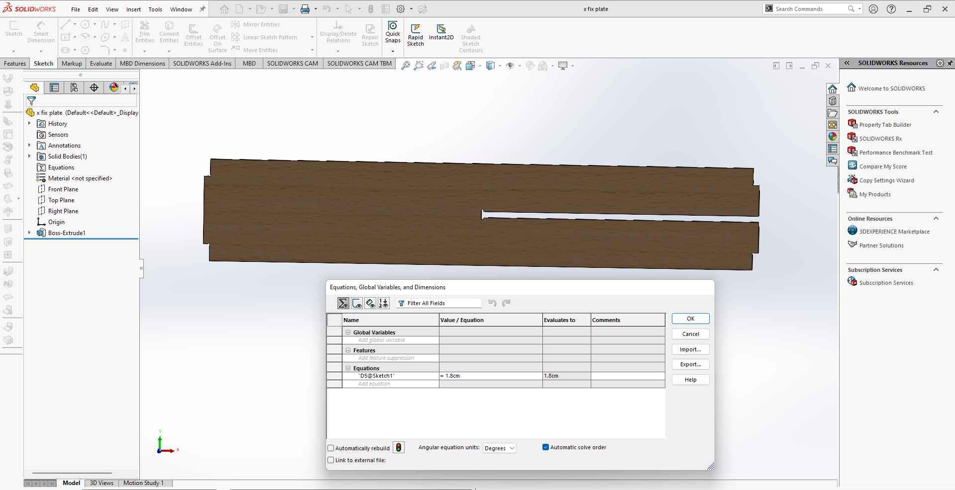
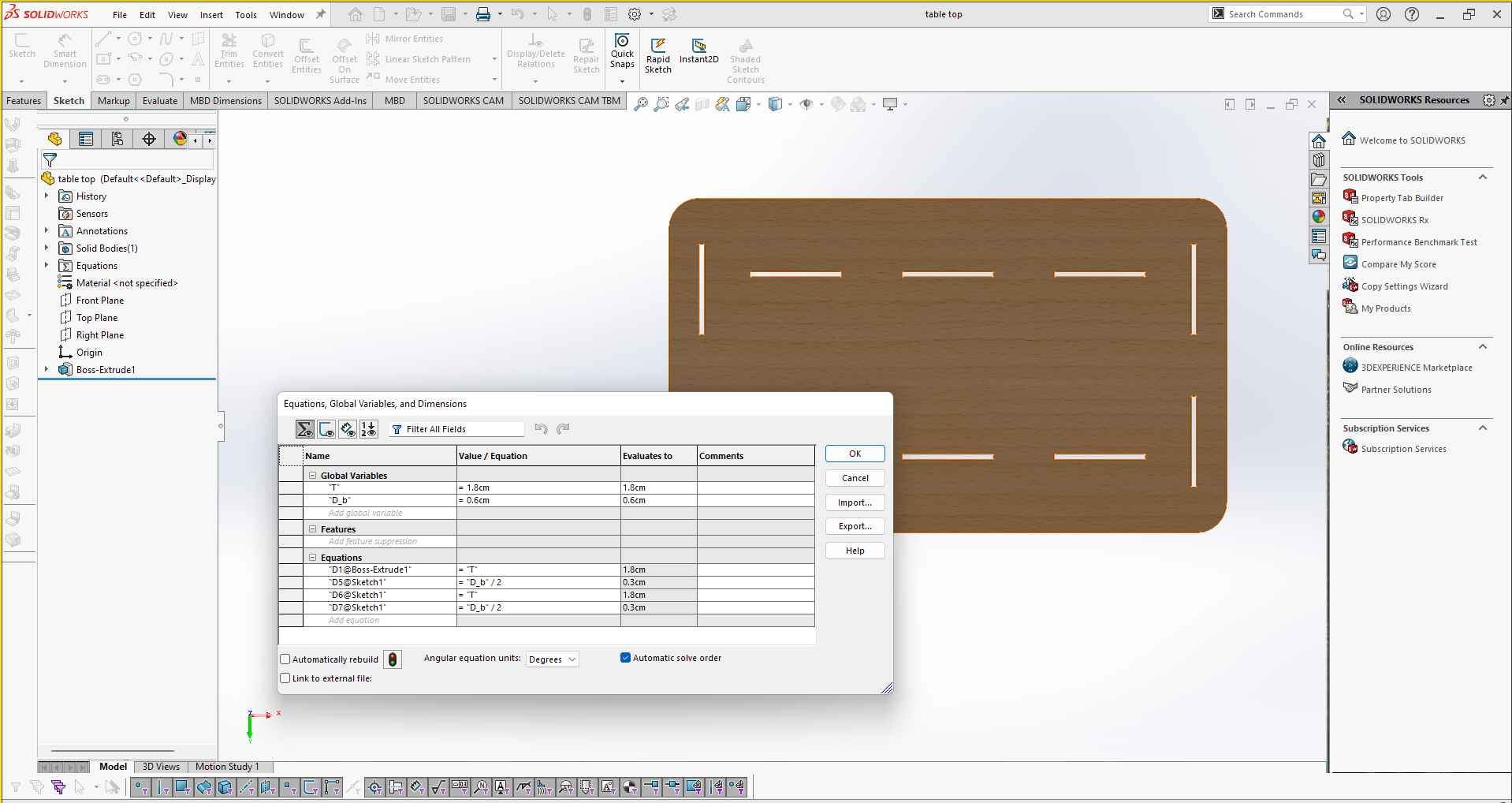
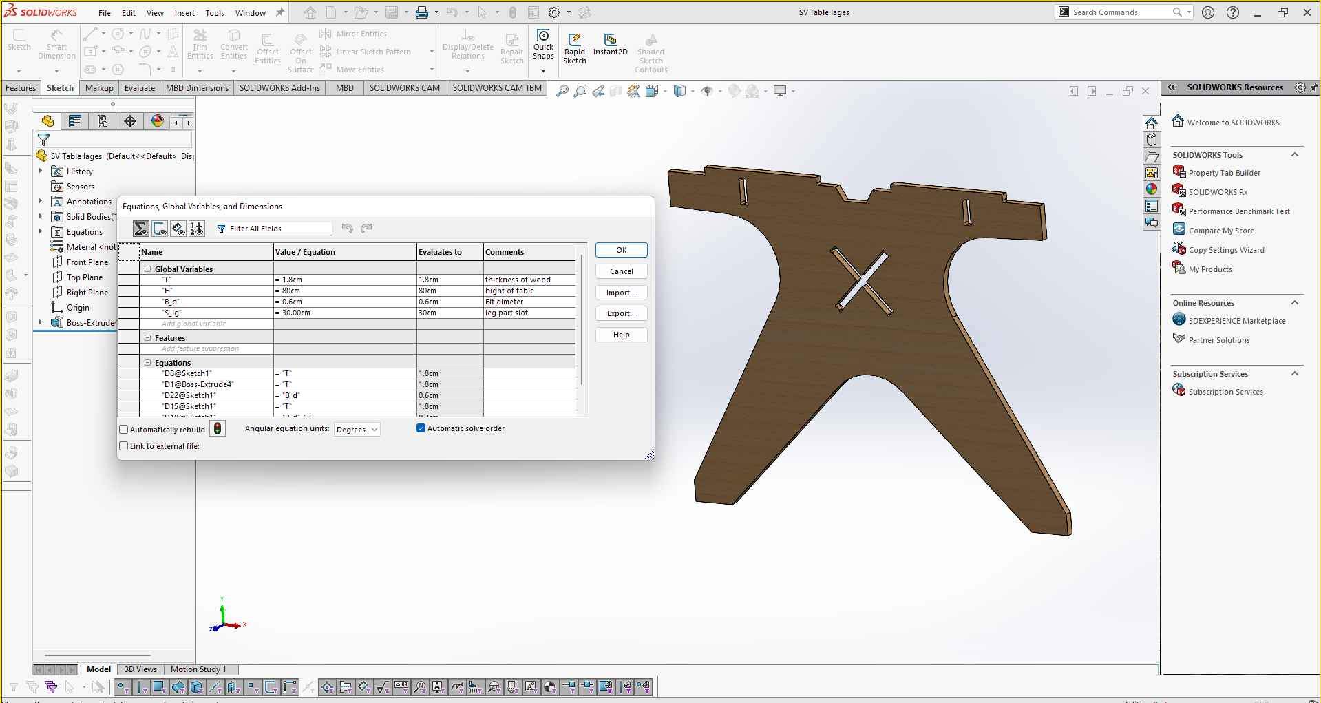
I make all parts in Parametric design because I was damn sure that the size of plywood we are using 16mm is not exact due to manufacturing error or whether plywood sometimes loses its exact shape. So to be ready with change in design If required at the time. I can change the parameters .
These are some common parameters I consider during making my parametric design.
- Thickness of sheet.
- Pocket size.
- Slot size.
- Milling bit dimeter.
I also designed a test part For measuring the thickness and responding to it above parameter for each sheet we are going to use. (we keep 4 sheets in inventory 1200mm*2400mm each )
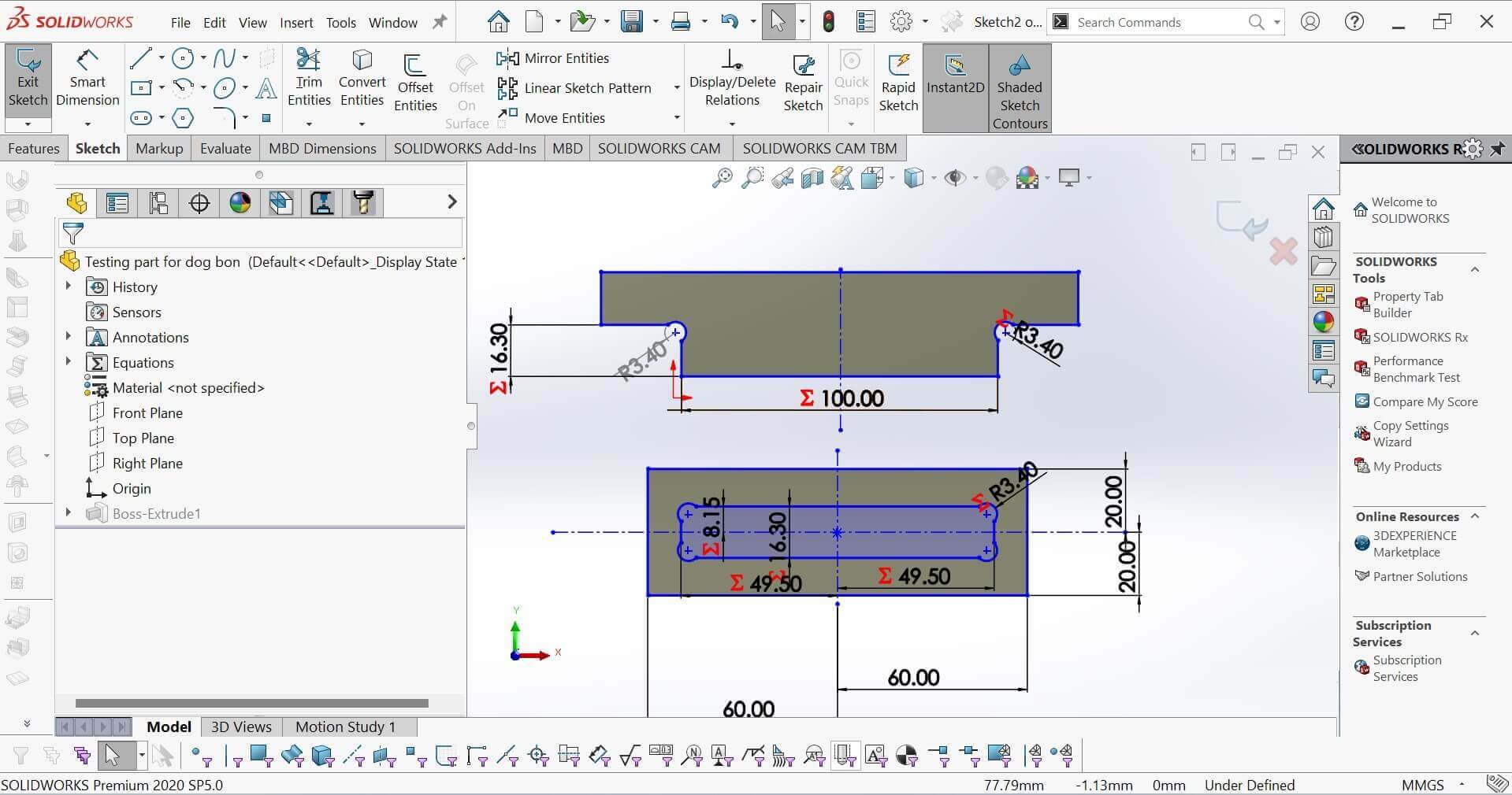
Test part.
Assembly
After making all the parts to ensure they will press fit properly and cross-check the dimensions are ok. I make them assemble in Solid works assembly.
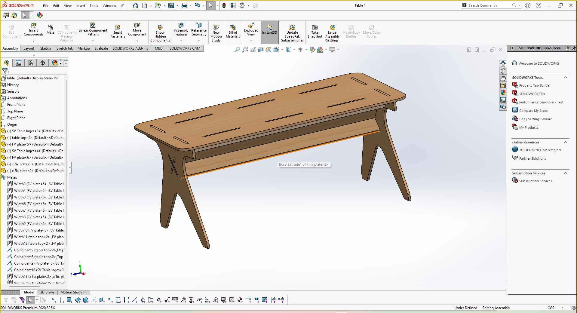
Final Assembly of Table in SolidWorks .
For this week Jaydip is also collaborating with me. He is working with the component rack for fab lab Electrical inventory. So with his help, I also designed the rack To make it mount on the table.
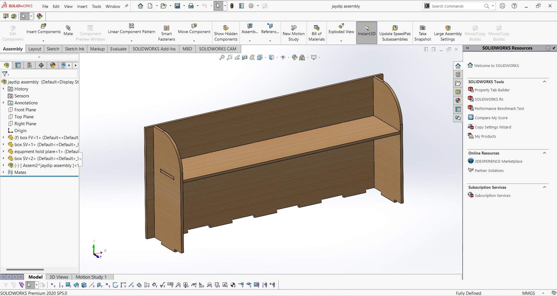
Jaydip's Assembly Table rack.
This is the fully assembled Soldering table ready in the Solidworks assembly environment.
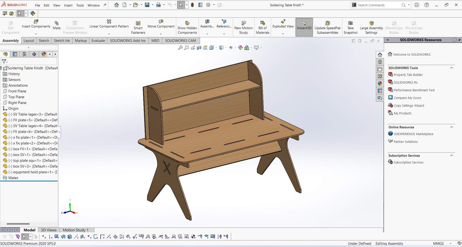
Final Assembly of Table in SolidWorks .
Have a look at a short video I prepare of Solidworks Assembly.
SolidWorks Assembly Video.
Creating Toolpaths.
For generating the tool path for ShopBot I use PartWork. A partWork is a CAM software used for generating G-code files/tool path files for CNC router machines. It required DXF file format to generate it. Below I explain how I use Partworks (Now, VCarve is being used)to pull part DXF files and create a toolpath.
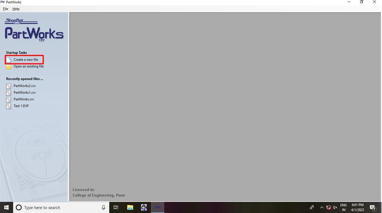
Creat new file in PartWorks.
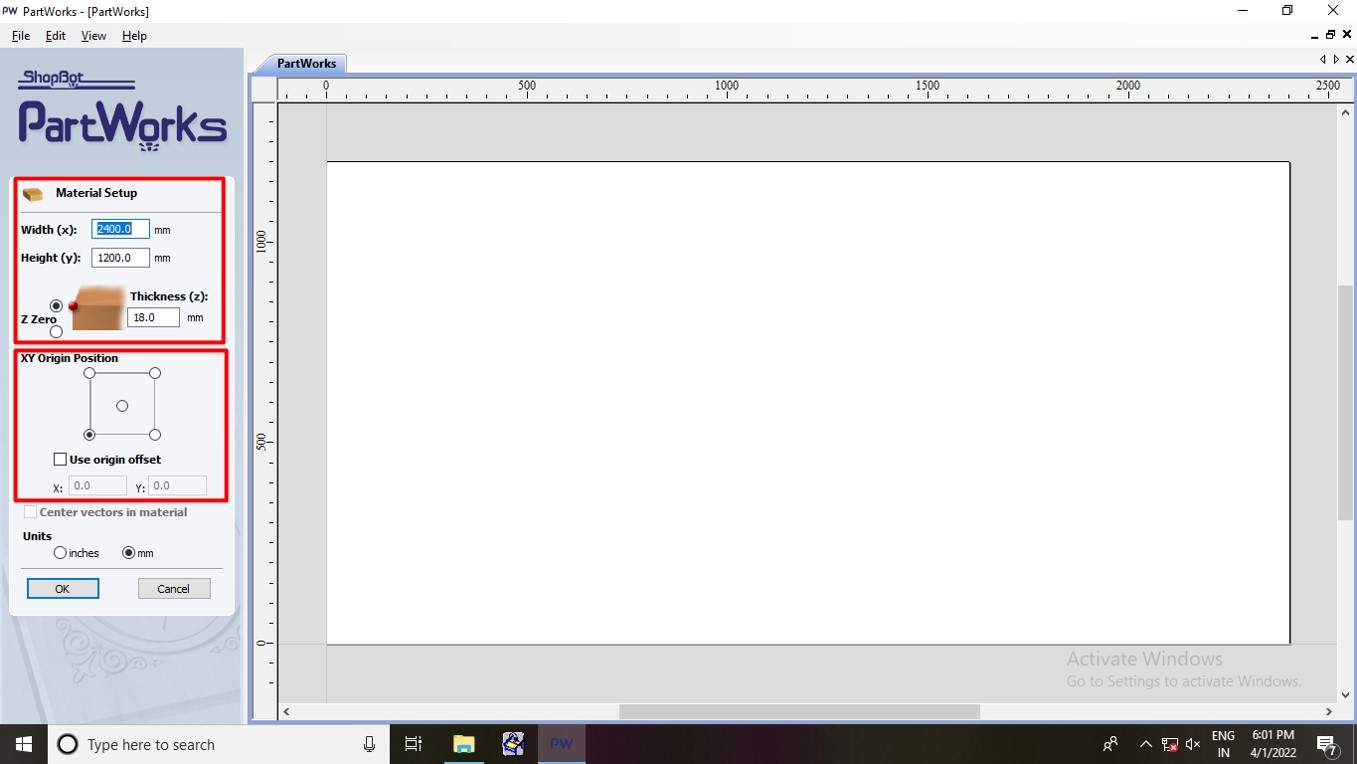
Matterial setup for shpbot.
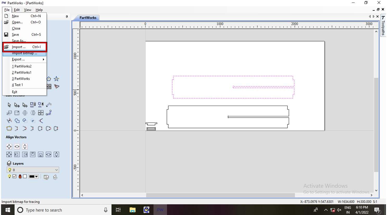
Import dxf files.
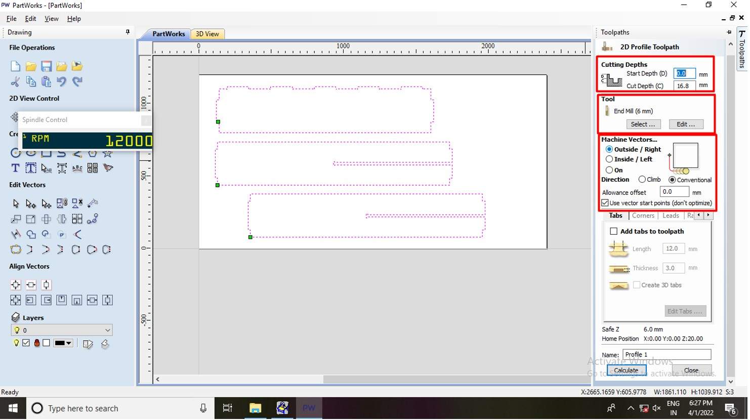
Toolpaths parameters setup.
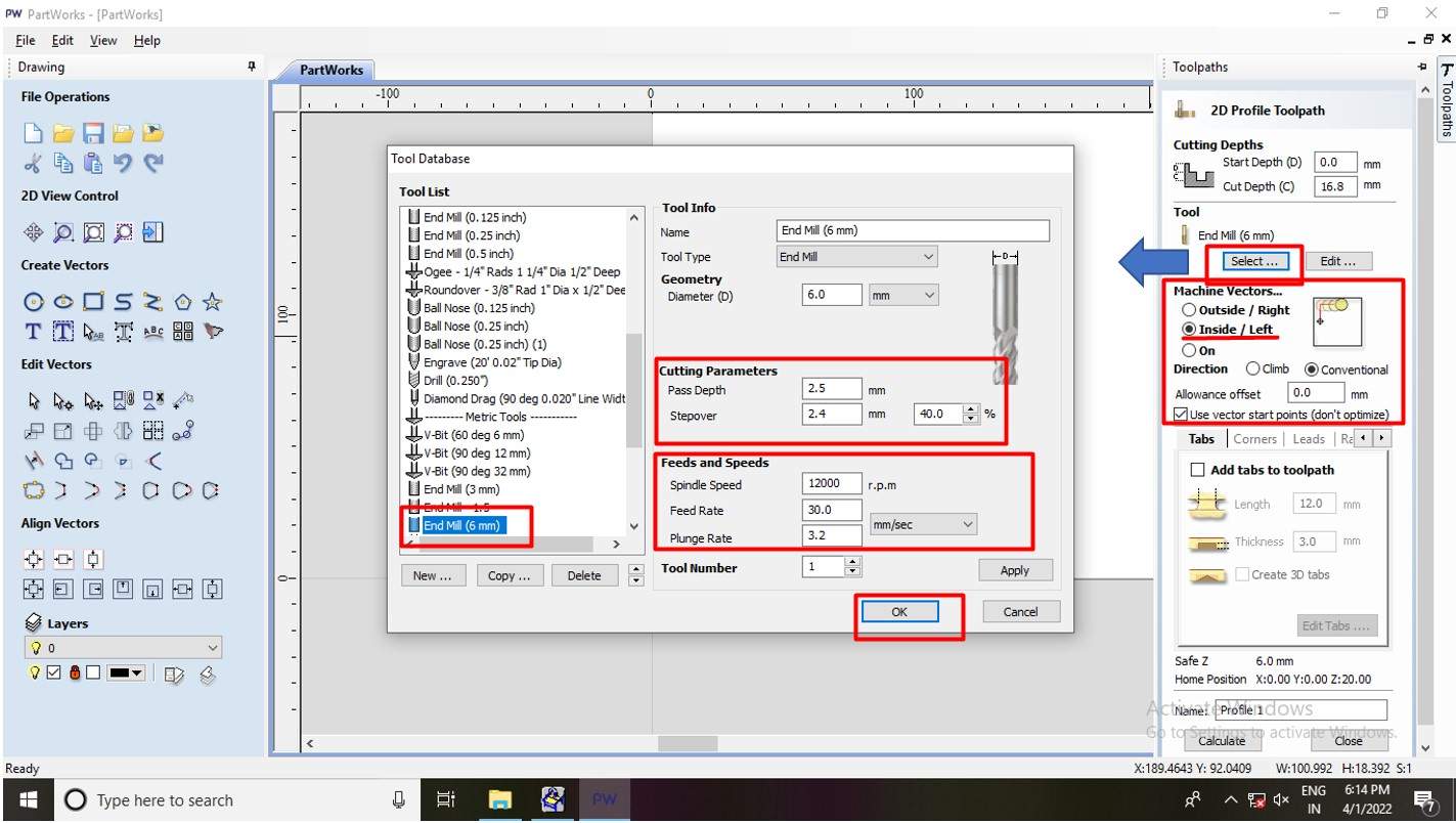
End mill parameters setup.
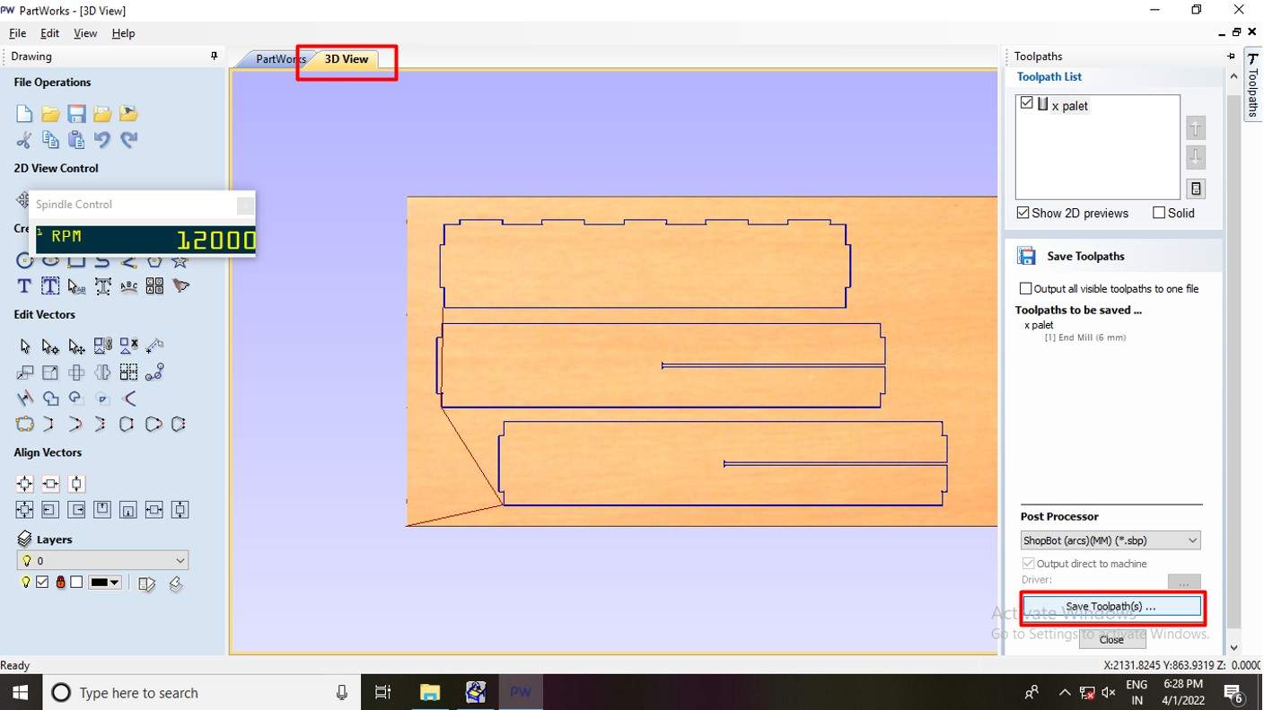
3d view of generated tool Path.
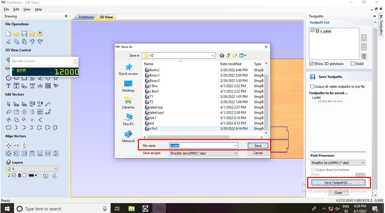
Save generated tool Path.
Set up ShopBot for milling.
Mounting of milling bit.
As I said, I am using a 16mm thickness of plywood. I need to change the milling bit to 6mm in diameter. As you can see I use the spanner to lose the bit from the collet and replace it with a new 6mm milling bit.
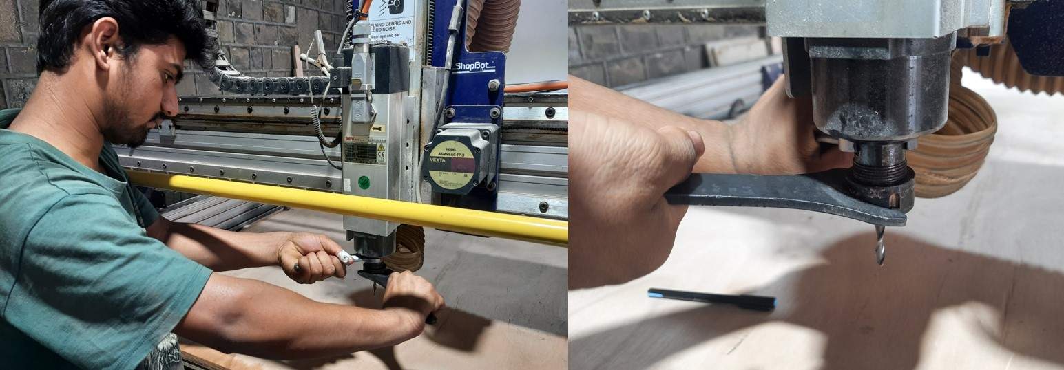
Milling tool mounting.
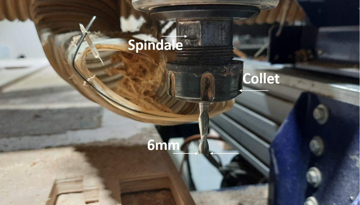
6mm milling tool mounting.
Mounting of the Plywood sheet.
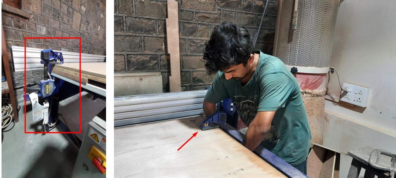
Clamp mounting to hold sheet.
As I told I am using a 2400mm*1200mm*16mm plywood sheet for our table. for mounting plywood sheet on shopbot bed. I use Clamps as you can see in the image. Make sure the clamp must mount in such a way that the end mill tool should not collide with it during the operation. I make sure to make the clamp under 50mm. From the edge of the sheet.
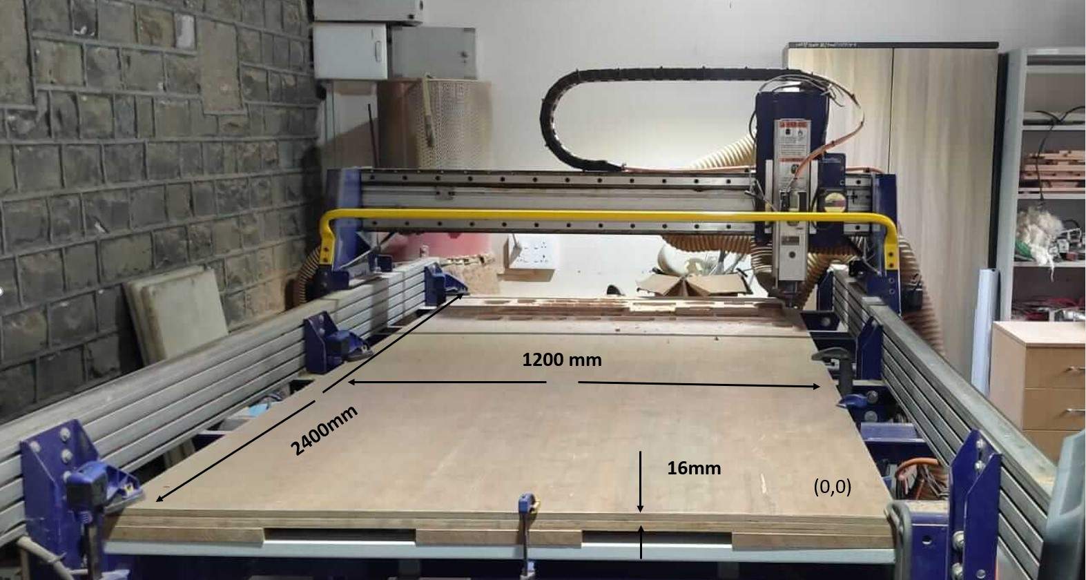
16mm Plywood mounting on Shopbot bed.
Cutting Parts on the shopbot.
To control the Shopbot CNC Shopbot has one software named shopBot Console. It is as easy as a laser cutter.Just you have to become familiar with it. In the following steps, I explain how I lode the generated tool path and set up the CNC ready for cutting.
1. Key to activate Spindle Switch and turn on the machine.
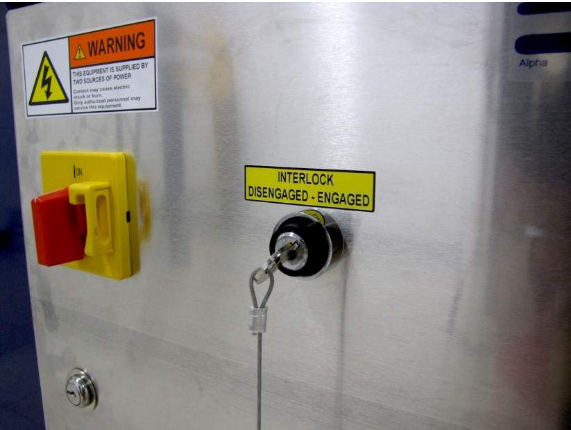
Turn on the man switch.
2. Don't forget to turn On the dust collector.
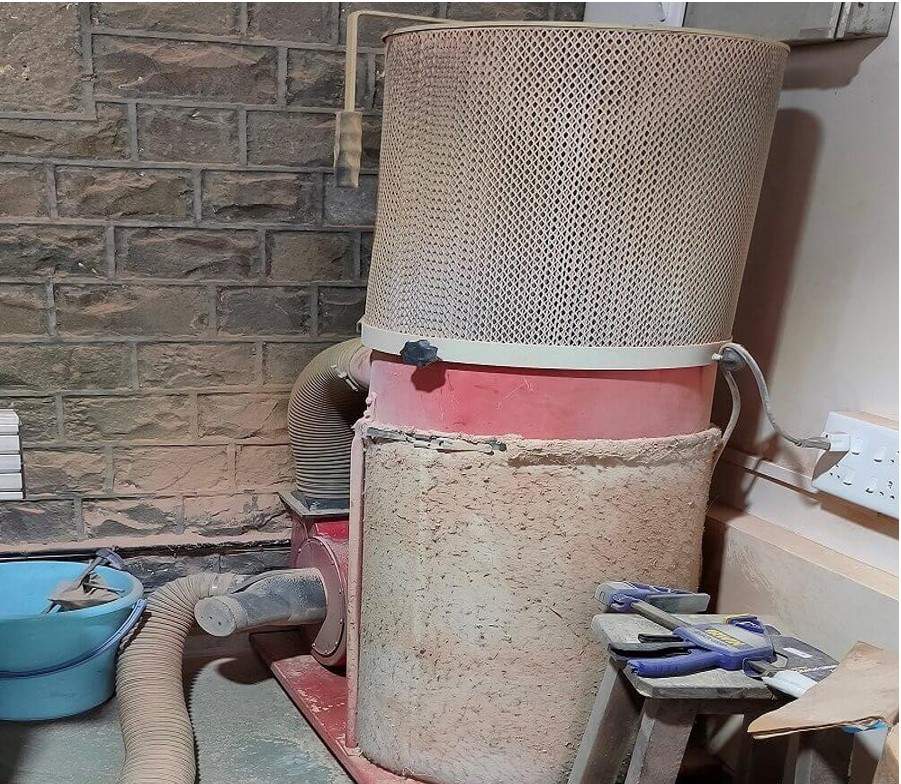
Turn on the Dust collecter.
3.Open the ShopBot Console window.
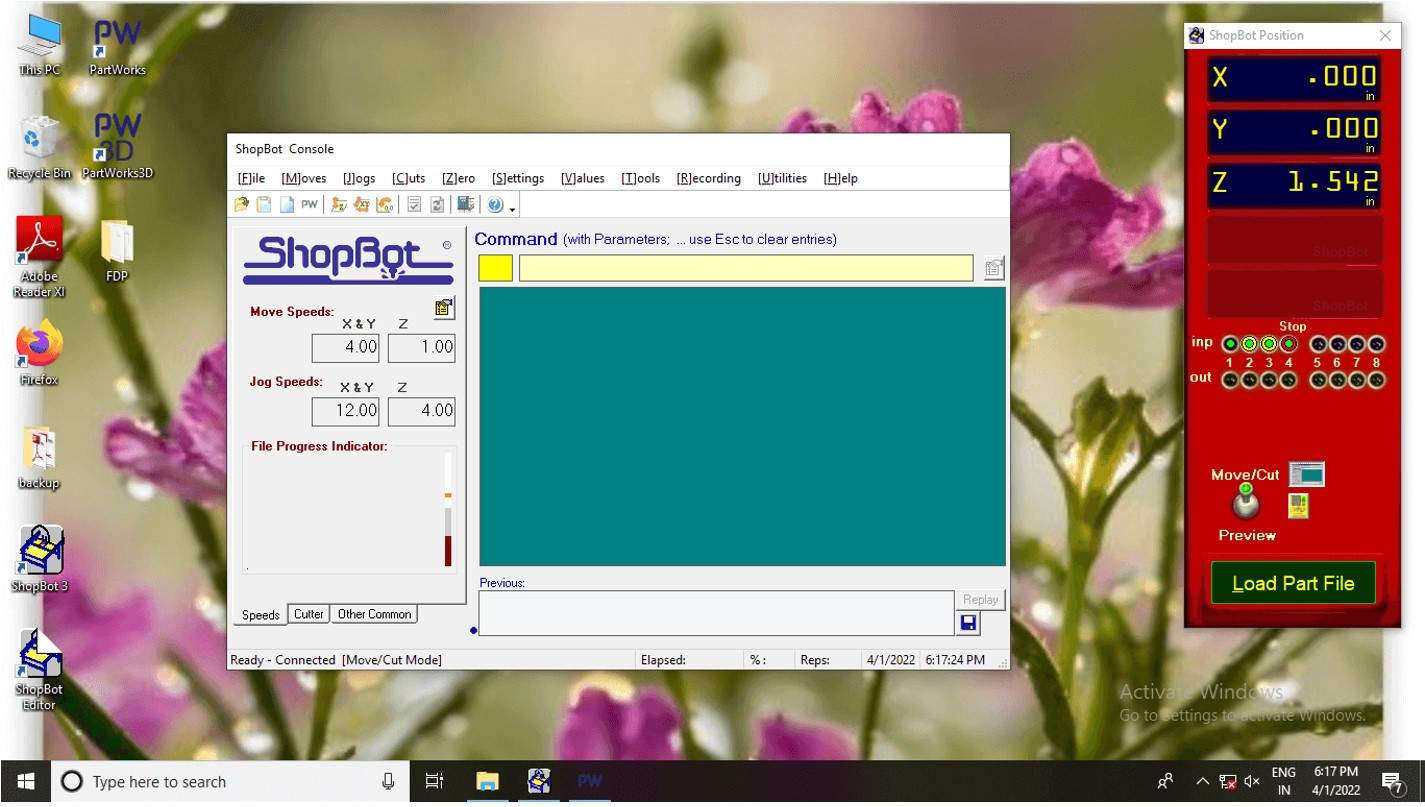
Shopbot console.
3.Click on the key pad symbol to open the keypad window.
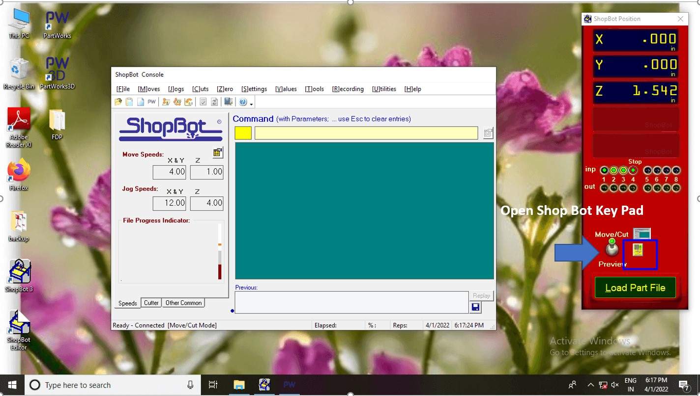
click on keypad .
4. Click on Keypad to Move the end actuator (Spindel )in a suitable position to make the origin. I chose the corner one. I use Arrow keys on keyboard to move x-y and page up and down to Z-axis.
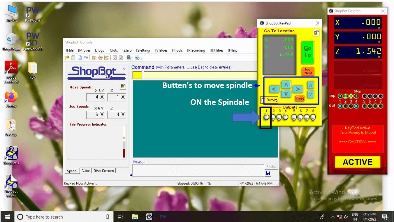
Start Spindle.
5. Turn on the Spindle by clicking on the 1st lever button. Start the spindle by pressing the manual start button.(if you find any error during the process on the machine not turning off please check if the End Switch is ON).
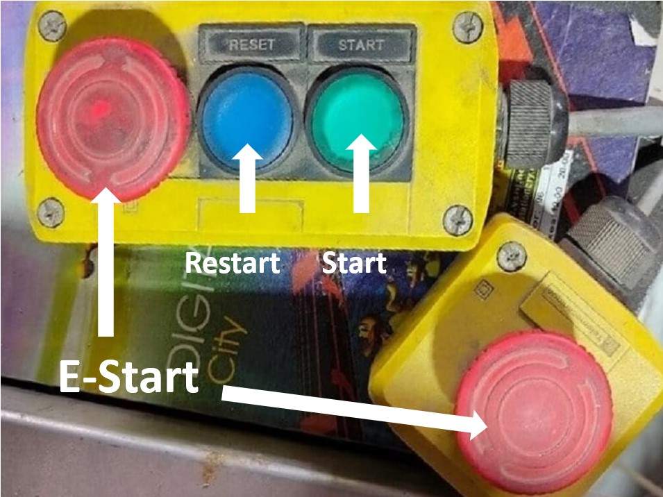
Manual Switches.
6. Now make the position of the spindle (milling Bit )on a sheet in such a way that it just touches the surface of the sheet. and turn off the spindle by pressing the same lever button.
7. Lode the PartWorks file by clicking on the Load Part file button from.
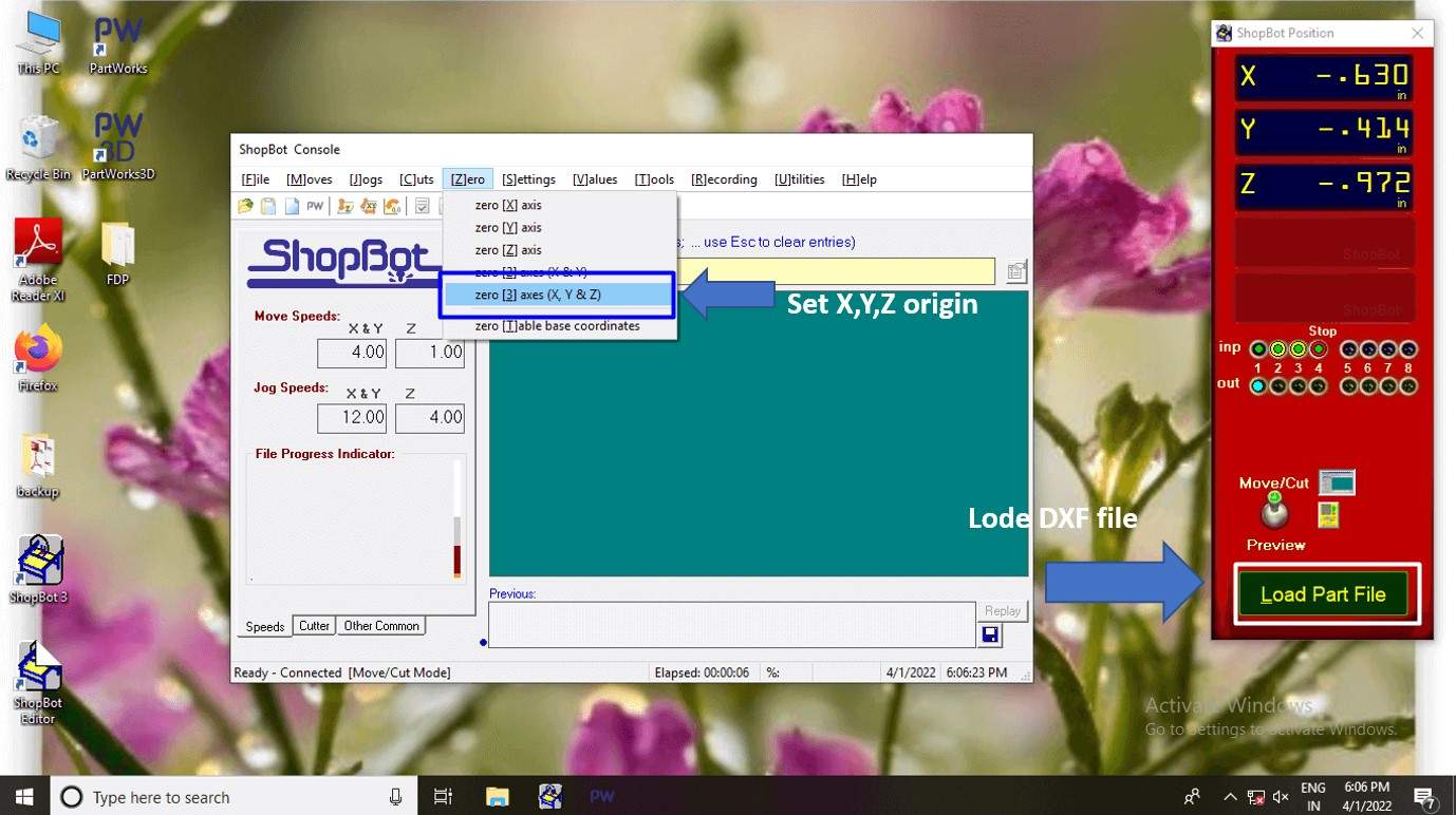
Set origin and lode the toolpath.
8. A sheet of confirmation will be appear as shown below. click on start button and the CNC will start cutting the sheet.
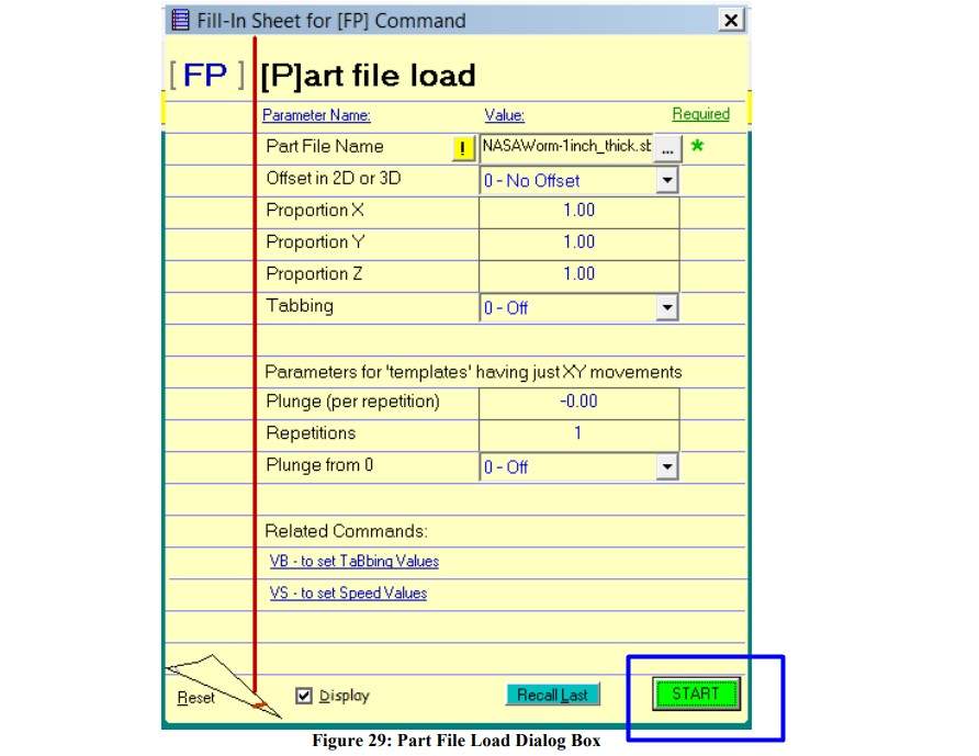
click ok yo run shopbot.
Shopbot milling process.
Dog Bone.
How to make Dog bone.
A very important part of this wood press fit design is a Dog bon.as we know CNC router can make any complex design but they fail with sharp squar corners because the rounded tool shape.which creat the problem in press fitting between two parts.though you can make this corner sharp 90 degree using a square file .but then whats the use of CNC shopBot machine.So heres come a Dogbon.Dogbon creates a circular arc that is outside of the edges. The point of intersection for both edges is actually the mid-point of the arc.
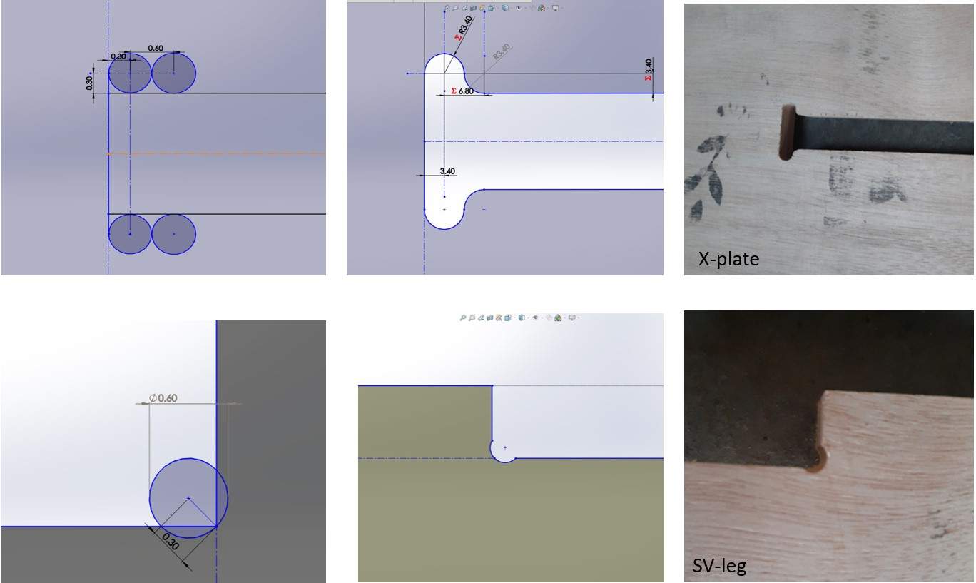
Some Dog bons in design.
This are some of the Dogbon fillet I use in my design.
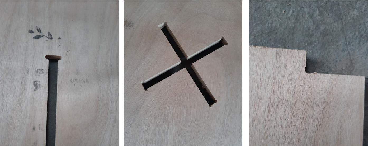
Dog bons after machining.
Some Errors while machining.
I got 2 error in this week .The first error was because of wrong tool pass by restarting the shopbod .the machin started moving in slightly opset direction.
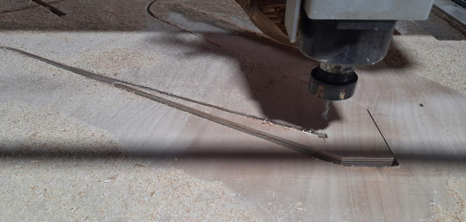
Errors while machining.
And the 2nd one was because unnessery vibration of cuted pice.at the last path of cnc cutting most of the part got fully cutted already .becouse of some vibration the part got dislocated,resulting unwanted cuts.
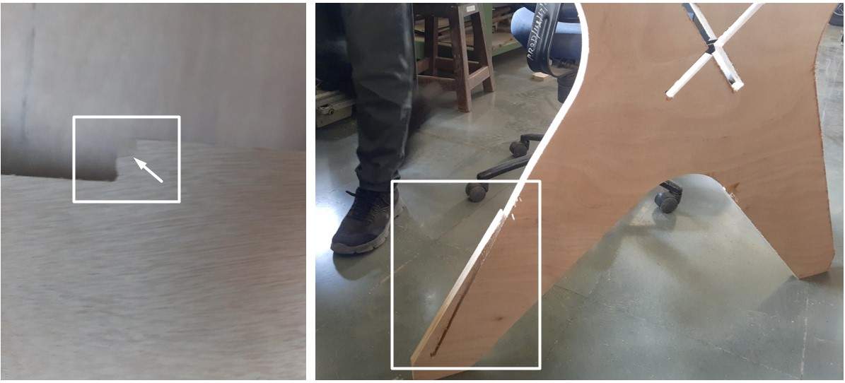
Errors while machining.
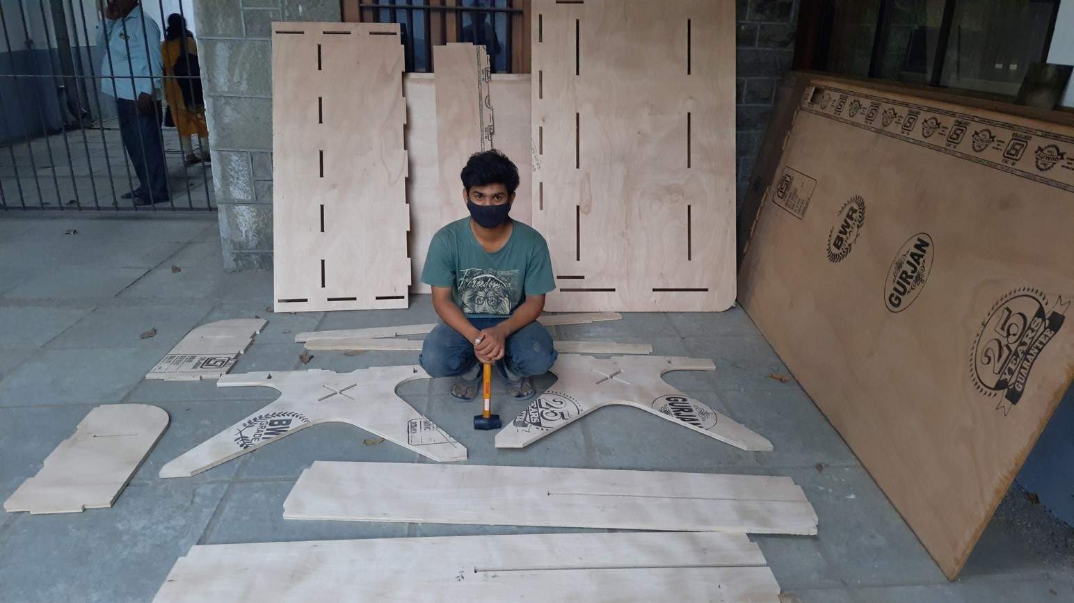
Soldering table Assembly.
Yippee ….Exciting moment this is me setting in between the Fab Soldering table component ready to assemble.
.
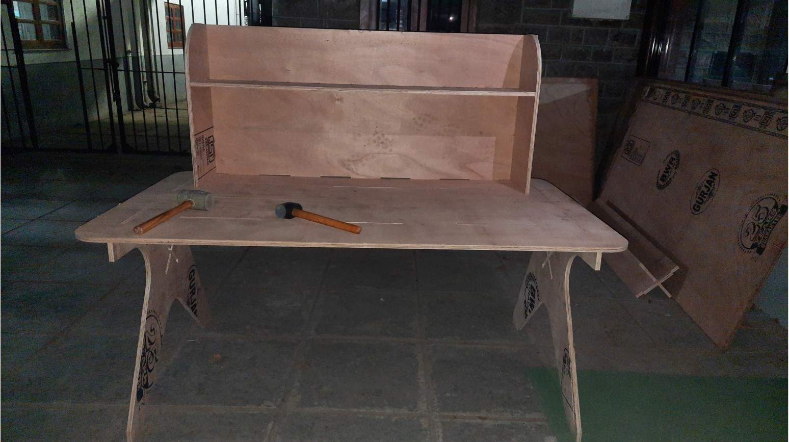
Have a look at this video where I and Jaydip are assembling the Fab Soldering table together.
As you can see all parts assemble perfectly except the x-cross plate support. It requires some filing. So we decided to assemble it later as we bring the Table to our place.
Hero short:
Testing strength of fab soldering table.
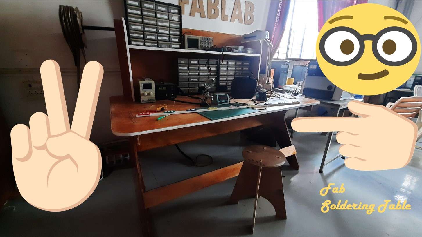
final assembled at our fab lab.