The task list for this week:
- Group assignment:
- characterize your laser cutter's focus, power, speed, rate, kerf, and joint clearance.
- Document your work to the group work page and reflect on your individual page what you learned
- Individual assignments.
- Design, laser-cut, and document a parametric press-fit construction kit, which can be assembled in multiple ways. Account for the laser cutter kerf.
- cut something on the vinyl cutter.
Computer-Controlled Cutting:
Computer Controlled Machine is used to cut material from stock pieces using computerised controls and mechanical tools. We must cut the 2D design using various cutting equipment in this assignment. For this week's assignment, several cutting instruments such as a knife, a lesser cutter, a plasma cutter, and a vinyl cutter were employed. We must use this cutting procedure on materials such as cardboard, acralic, MDF, foame, plywood, and paper.
What is Laser cutting:
LASER cutter is a 2.5 D CNC machine use for subractive manufacturing process .It use high wattage LASER as a end tool which cuts the 2D form of structure .In our lab we have a C02 base 60 watt LASER cutting machine .
Leser cutting machine in FABLAB at Vigyan Ashram:
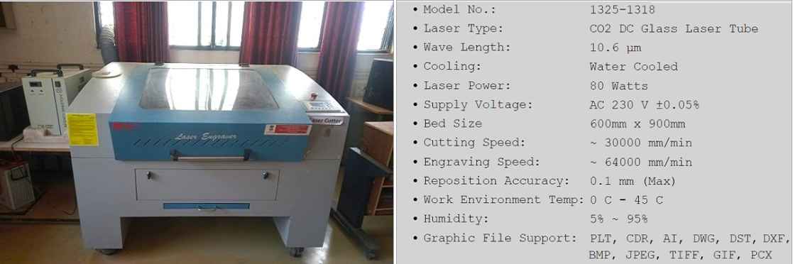
LASER cutting machin in our Lab .
For more information about this laser cutter, please visit this page: SIL CO2 Laser Cutter.
Group assignment:
This was our first group assigment ,where we all have to study various parameters of cutting mashine. such as focus, power, speed, rate, kerf, and joint clearance .This collected data is helpful for each of us in our individual work with our CNC lasercutter. Some of activites I did in group are as follow:My contribution:
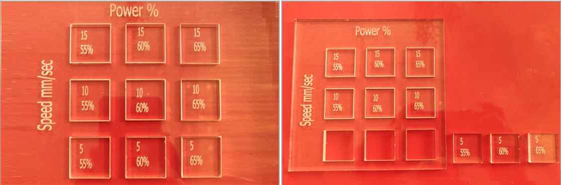
Best power and speed combination for effective cutting:
For knowing the best power and cutting speed.me and devesh chouse Acrilyc sheet for study mechaning.we took 4.4 mm sheet and design a combination of set of square cut on cnc LASER cutter with varing power and speed to check how material response to different power and speed and examine which combination works effectively.
LASER cutting machin in our Lab .
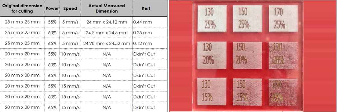
Conclusion: We then calculated the optimum speed and power settings for 4.4 mm thick acrylic sheet. The left most image below show that the machine was not able to cut through the sheets at a speed of 10 mm/s even at a power of 65%. If we had increased the power above 65%, the acrylic sheet would have started melting. Looking at the results, we concluded that for a 4.4 mm acrylic sheet, if we want to cut with a speed of 5 mm/s, we will need to use 55% - 65% of the power. After that, we also calculated kerf values. The right most image below shows the engraving done on acrylic sheet. We were able to engrave with very good quality for the same acrylic sheet at a setting of 25% power and speed of 130 - 150 mm/s.
Kerf width calculation:
Here we took the same Acrilyc sheet to work on. I found not a single machined part cut at exect thickness as expected also the cutting tolerance varies base on speed and power.to calculate kerf width we collect the data of each cut portion and subract the machined portion measurement witht actual designed one. Following is the data base on ehich we calcullate the kerf width :
Conclusion: following is the table of result for 4.4 mm Acrilic sheet.
.
Check here to read more about our group assigment.
Individual assignments:
parametric modelling :
I know CAD design but this portion of designing was very new to me.Parametric modeling is the method of Modeling in which we using parameters in design . The benefit of parametric modeling is that anyone can edit the parameters any time by just changing parameters and if there is constrait or relation this parameters then whole model can be modify with just modifying one or few parameters. Design will adjust itself accordingly on basics of change in parameters hence no need to design it again.
Ideation :
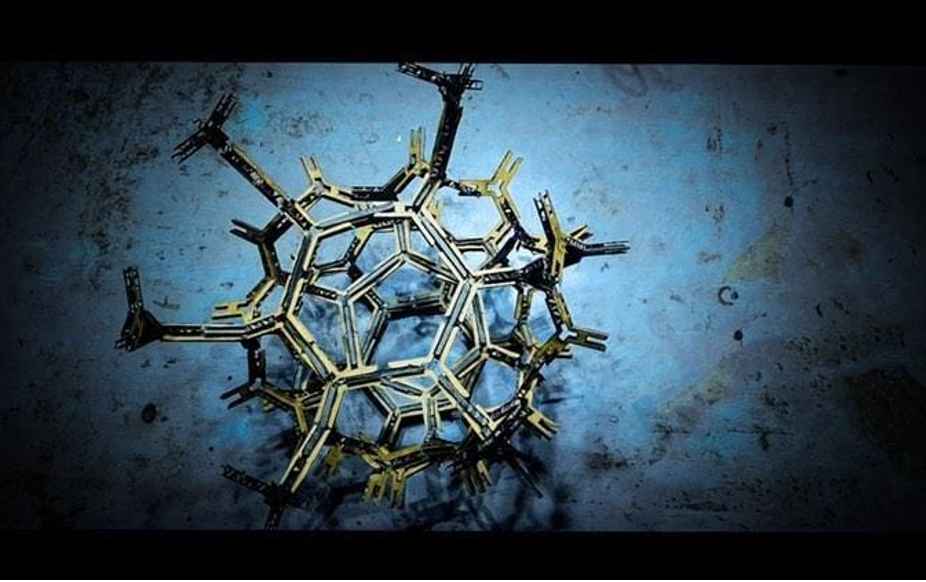
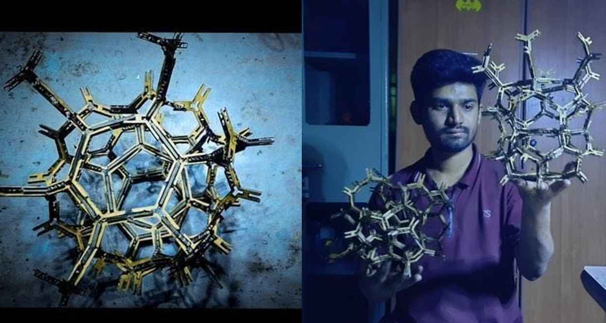
So for my parametric design, I search several 2D designs from google but Dont like them all. Finely I got something in my lab which I decide to modify further.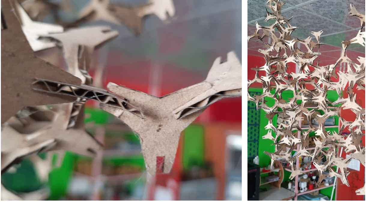
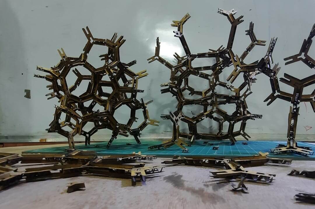
Dendride like structure.
So for further updating this structure, I try to make some slots between the original structure and press-fit it in one more other way hoping it will make something beautiful at the end. I also want to try making the outer connecting branches parametric so that I can change there no. to make a similar structure with more branches.Parametric modelling in SolidWorks :
I use Initially solid works for designing my parametric model. For opening a parametric sheet in Solidworks first got to Tool in the menu bar then in the tool, you will find Equation.
Steps :go to Tool>Equation >parametric sheet .
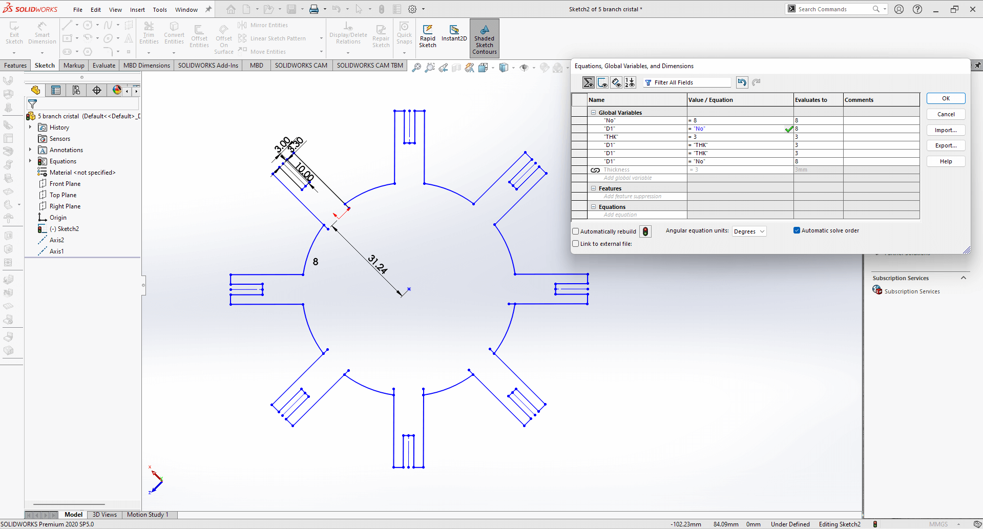
Solid Works parameter design
I tried a little bit in SolidWorks . but then one of our instructors Rohan taught us Parametric design in Fusion which I fill comfertable with as compared to Solid work's parametric design So I decided to shift to fusion 360.
Parametric modelling in Fusion 360 :
Then I move towards fusion 360. So I started working on fusion from this moment I have explored it a little bit but not that much as compared to Solidworks . But as I say in the tutorial I become a little bit more confident about fusion parametric.
To open parametric in Fusion.
Steps: go to Modify>Change parametric sheet.
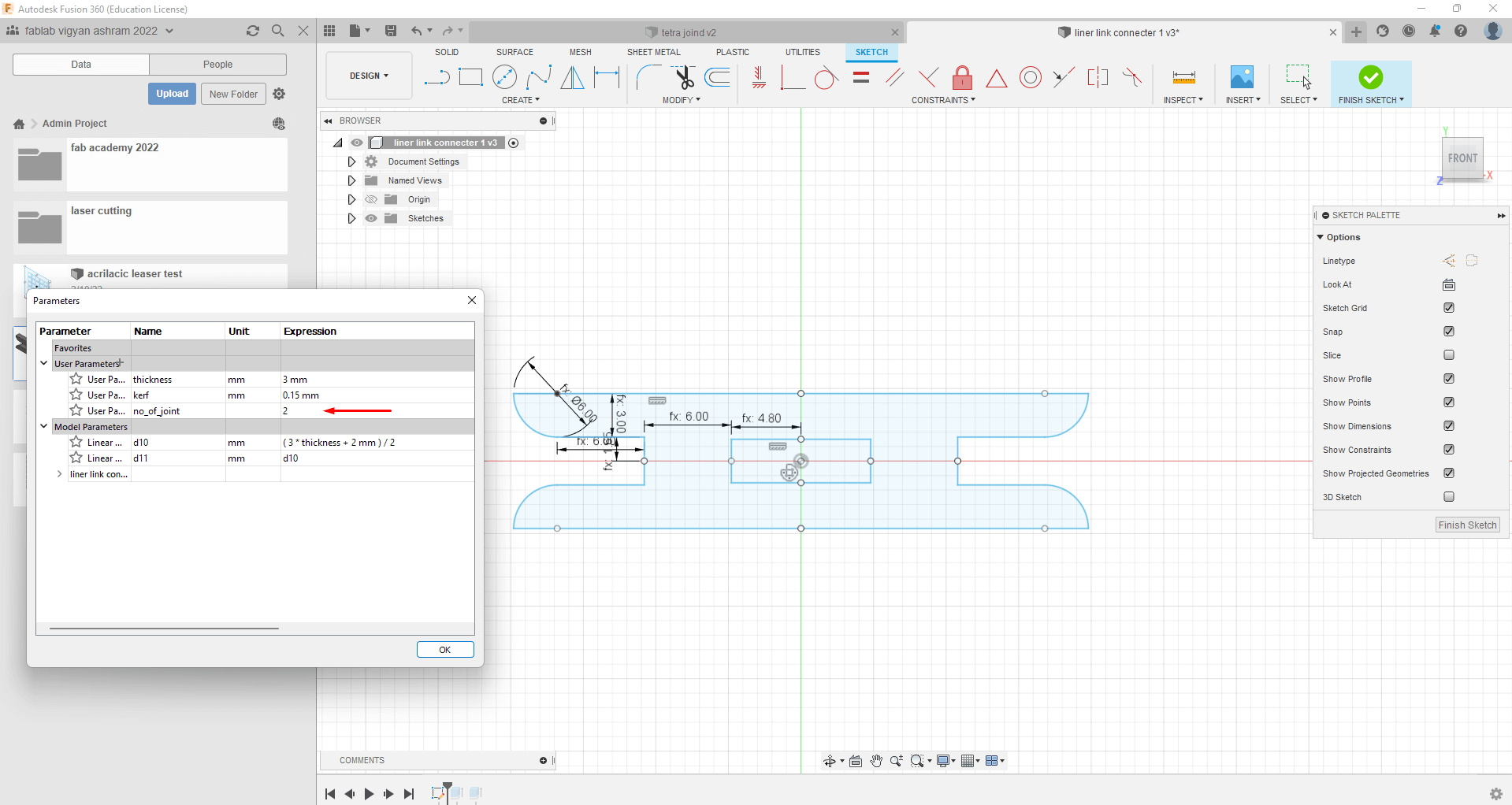
Design with parameter -No of joints -2
I try to make my parametric design for the parametric construction kit elements.Which was base on 3 parameters.
- Thickness of sheet -Define for the material thickness in my case I was using 3 mm card bord.
- Kerf -Kerf value for the mattericl which is going to cut in my case it was 0.15mm
- No of joints-It was for the no. of joind the press fit kit element have.
I try to make fillet as shown In the design to make it easy to assemble.
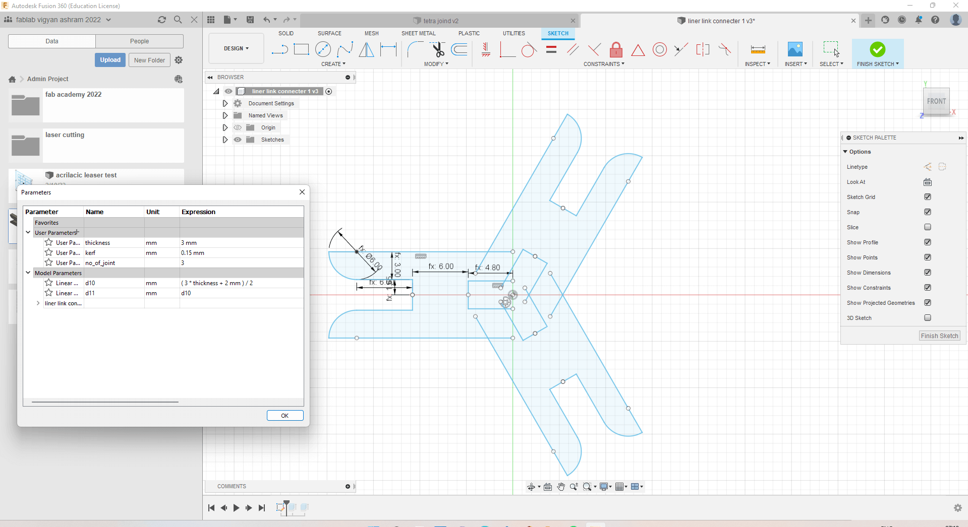
Design with parameter -No of joints -3
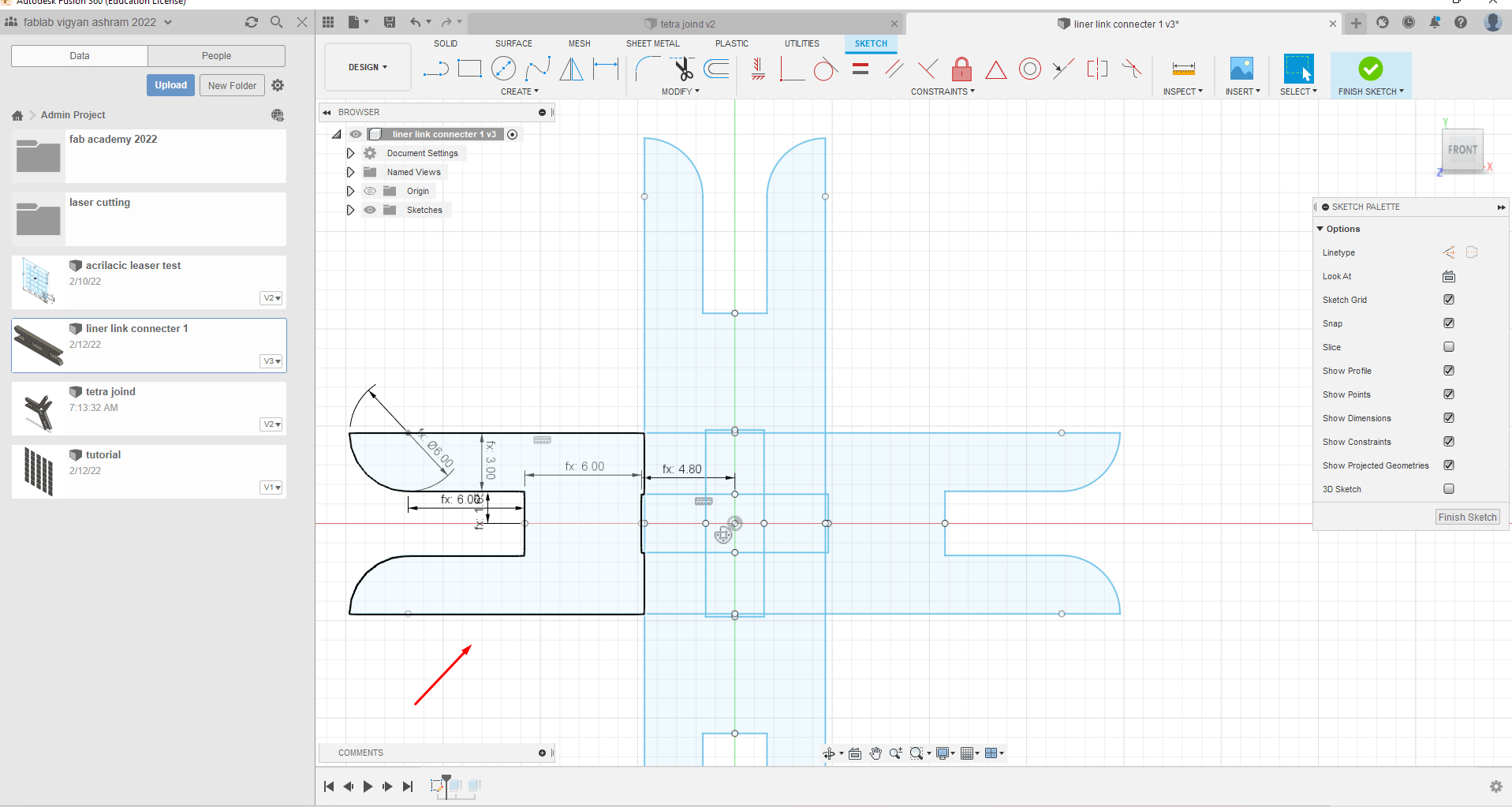
Design with parameter -No of joints -4
Stop point-I triend to make it for as many as point I want to cover .but I failed to make one up to 3 I tried to increas distance between center to over come the problem.After spending some time I decided to move and go for next task.
Save as DXF file:
As you can see this skech is not a total loop .It contain many lines in syde the loop .If I export this skeches in DXF the internal cuts will damage the press fit .So as a solution I first project the body edges as skech and then Save thas skech as a DXF file .I did it for 2 joint and 3-joint press fit respectively.
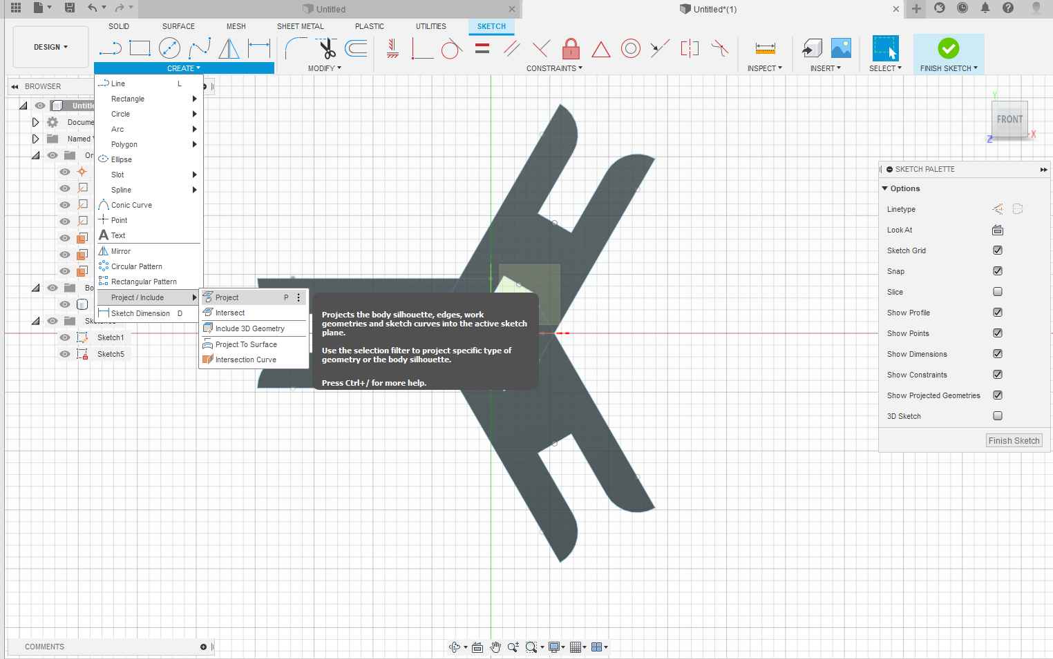
Projection In fusion 360.
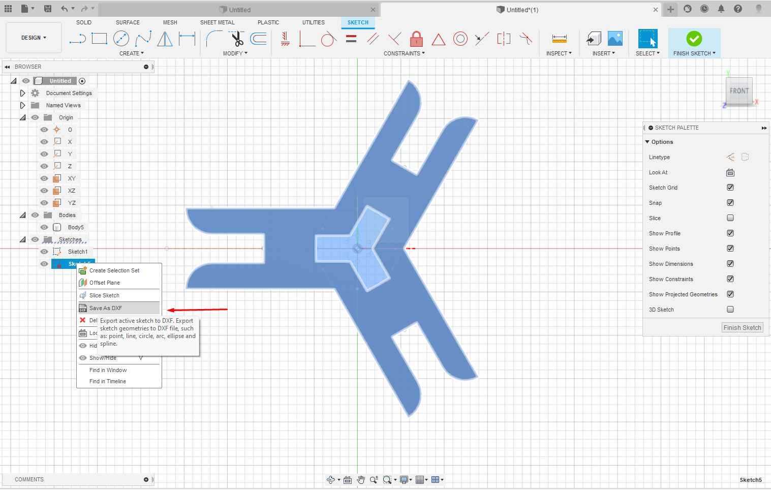
Saveing DXF file in fusion 360.
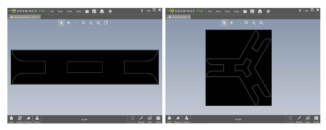
DXF files for 3 joint and 2 joints press fit.
Cutting the press fit Kit:
For making my press fit kit I use 3 mm cardboard sheet and cut it on 60 watt CO2 LASER cutter in our fab lab.
RDworks V8:
For Sending my press-fit design to the LASER cutter I use RDworks which is a free application to easily perform LASER cutting. It is very handy to use I just go to Files > Import and import the DXF files I save from fusion 360 then I use.
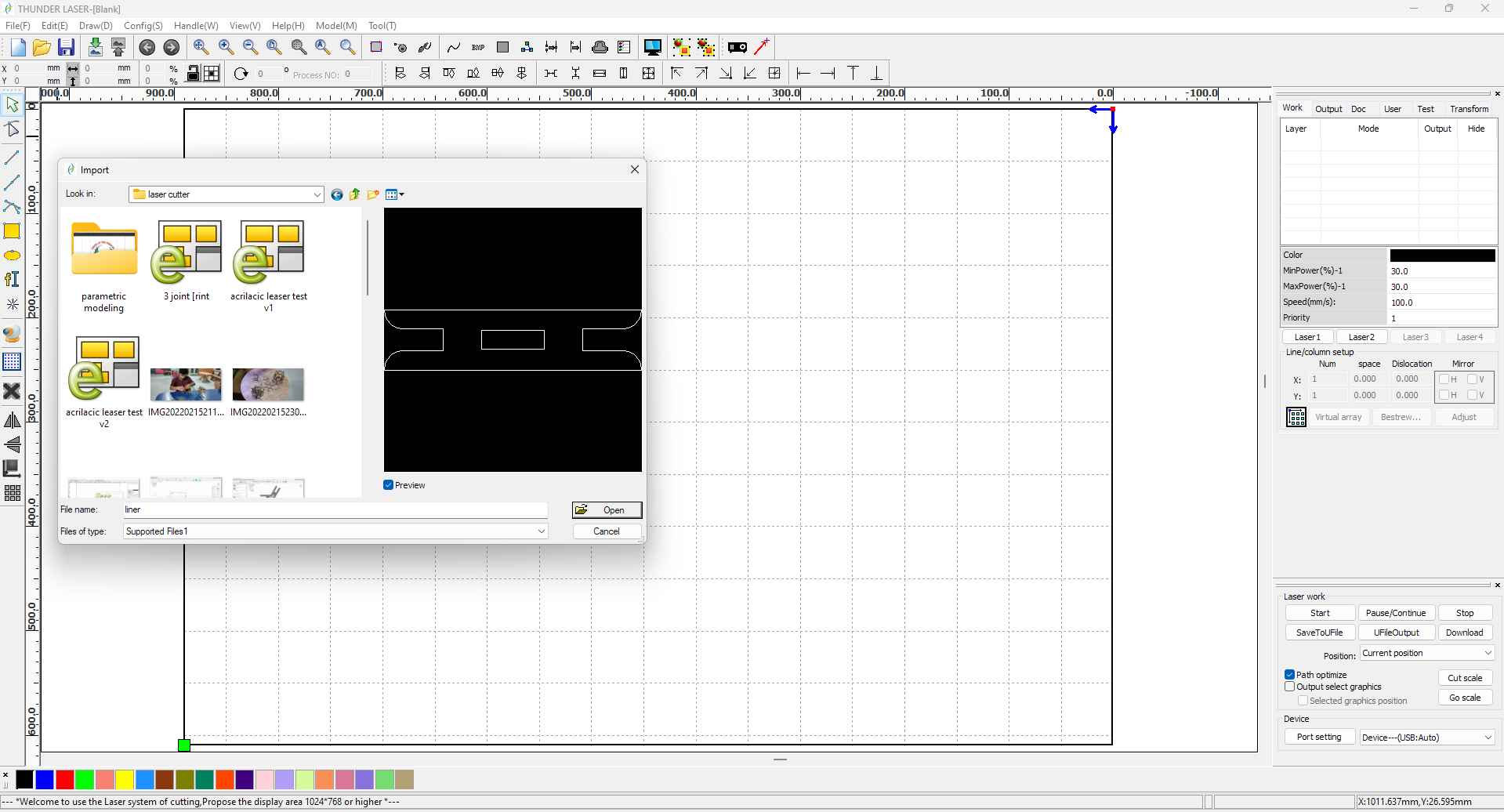
I multiply the cutting parts using the copy and Array command and send the file to LASER cutter firmware by clicking on the download button.
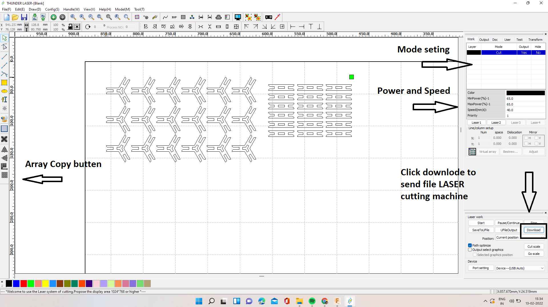
final cutting arrangement for press kit.
Values that I ModifyOrigin Roland SRM-20 milling machine in module.
- Mode - CUt
- MinPower- 65
- MaxPower- 65
- Speed- 40
- Priority- 1
Seting the LASER cutter:
For the LASER set-up, I follow all the necessary steps as I mention earlier in the LASER cutter section.
From starting power supply to turning on exos fan. Make sure the LASER must be off while not in a running condition also not forgot to start the compressor while running the LASER cutter.
I arrange the 3 mm card bord sheet on the bed of LASER Cutter .and open the file in LCD control Panal of LASER cutter. TO set origin of design on cardbord.I use the following arro buttens to move the end Actuator that is laser .on a suitable point having enuff space for my cut.I also chek the area required for my cutting by pressing frame button on control panal .After clearing all this steps I start the LASER cutting operation (ON the exost and close the safety cover on LASER cutting machne.)
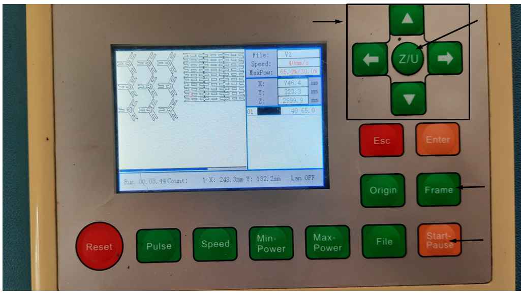
LASER machin control Panal.
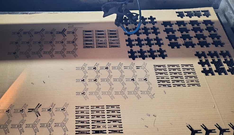
Cutting ready designe .
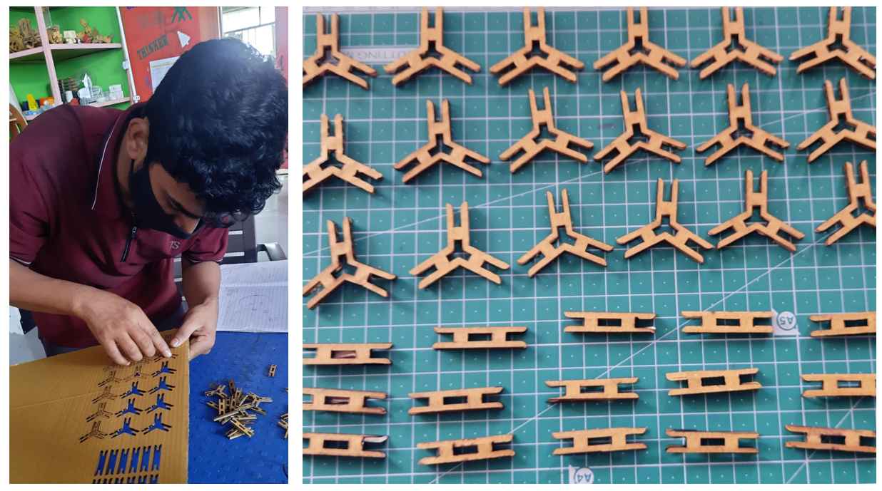
Seperating the press fit elements.
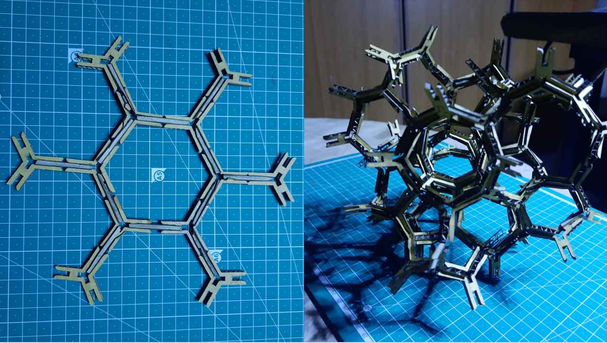
Assembeling the kit.
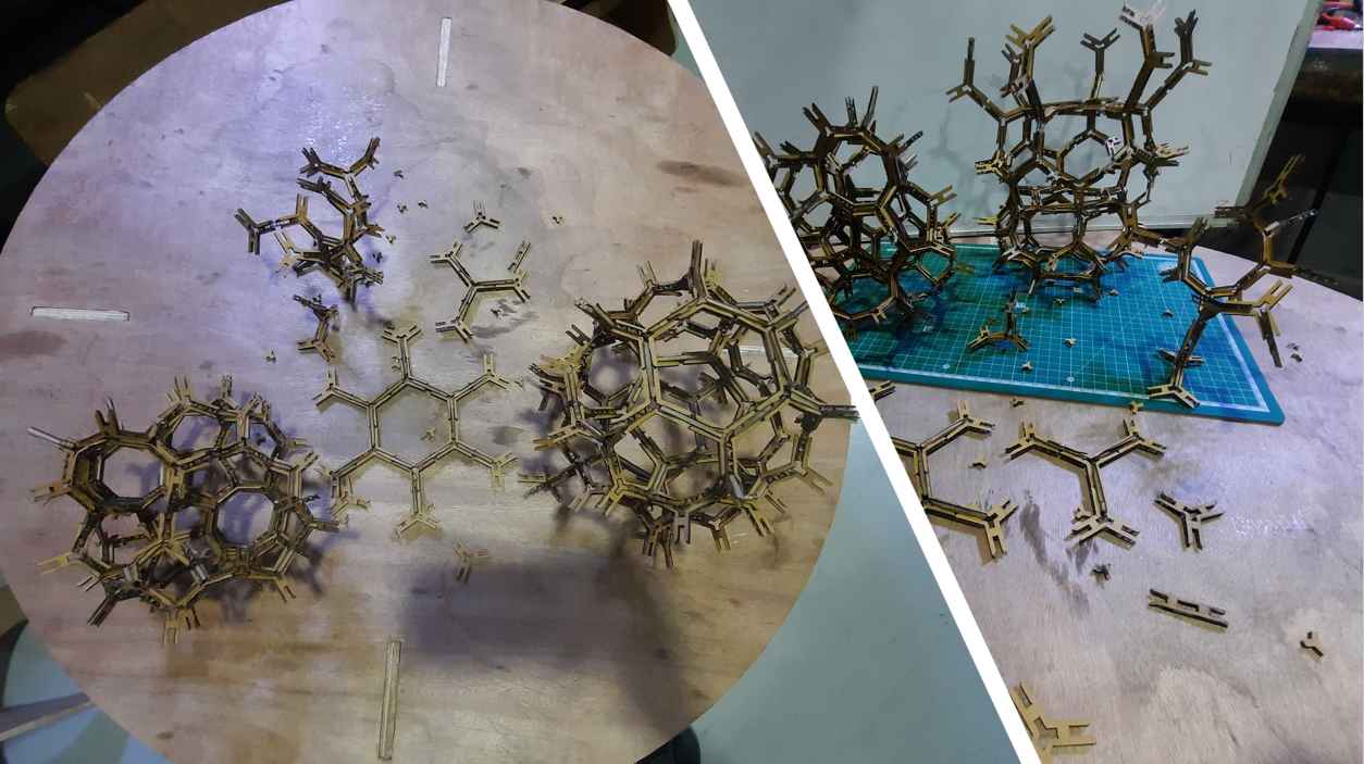
I make the kit but I was confuse what to make out of it .So I call my 2 more friends to help me making something out of it. we make various structure like aeroplan animals prees towers etc using this press fit.
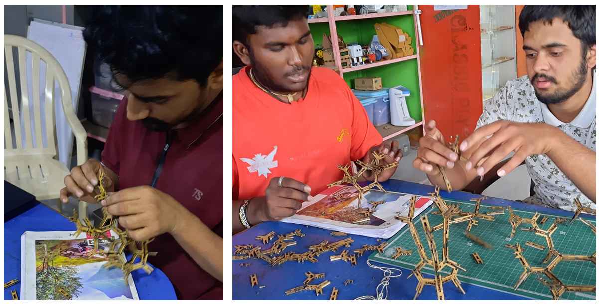
Assembeling the press fit Kit.
Hero shorts.
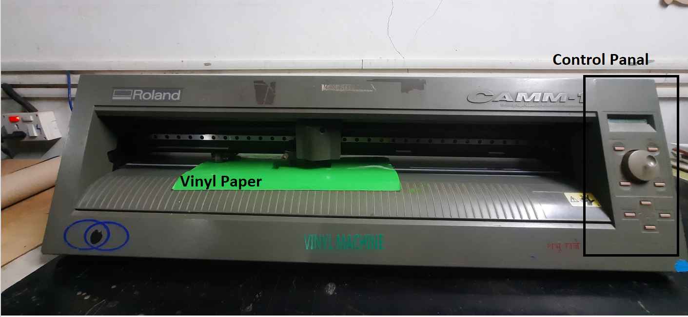
Paper Cutting machine:
The 2nd maching I use in this week is vinyl cutter.we have Roland GX - 24
vinial cutter available in our lab.I use this machine to uct stickers for me
FOr that I pick the ROG design log and cut it on a vinile paper .
For guid how setup and cut on vinyl paper I fallow this
tutorial
.
Values that I Modify
vinylcutter Force and Speed setting
- Force:- 130gf
- Speed:- 1cm/sec
make sure to select the correct setings and adjust the rollers on wighr bor limit.Also place the Paper on IR sensours on vinial cutting surface.
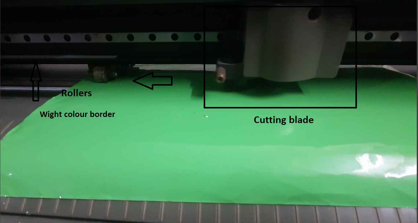
The following are the specifications of the Vinyle cutter available in our FABLAB:-
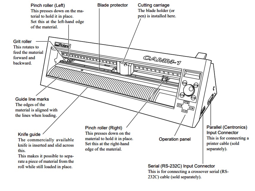
Vinyl cutterspecifications
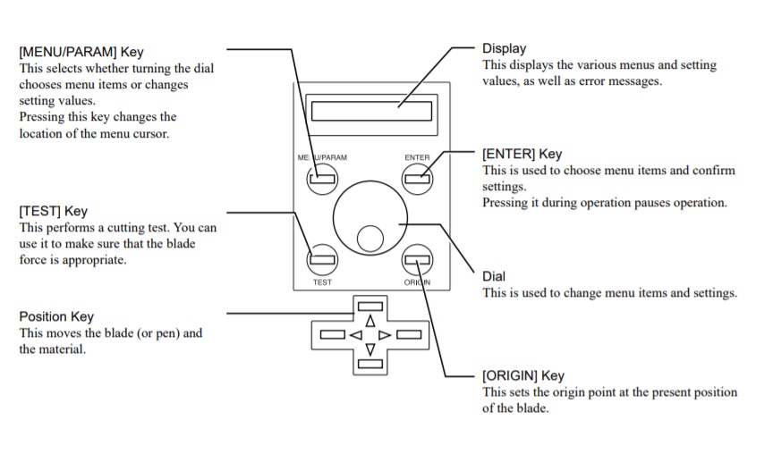
Vinyl cutter control panal specifications.
Logo Design:
I dessided to make a ROG (republic of gamers) log for my Laptop (Asus Tuf A15) For that I edit the Image in Inkscape And Export it in PNG formate .I also design my name on Inscape for making the logo.
Open Mods CE:
This time I use Modes which is a open source software .I use this software to creat RML file and communicate with Roland GX - 24 by seting serial connection using a USB caple.While connecting them I have to change the COM port name according to my machin .here is how I did it.
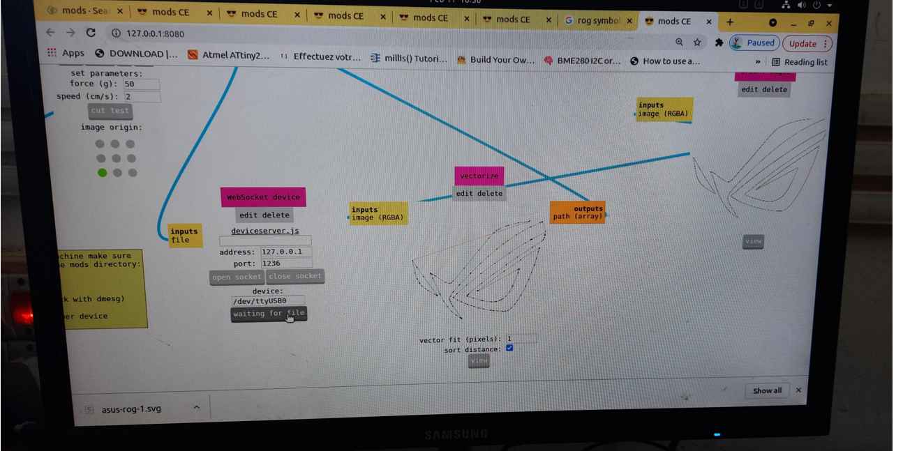
generating file for vinyl cutting.
Appling the stickers:
After cutting the logo I stick it to the back side on some masking tape and then gently apply this masking tape on my mobile cover to stick it and remove the masking tape to give a nice finish left sticker on mobile cover.
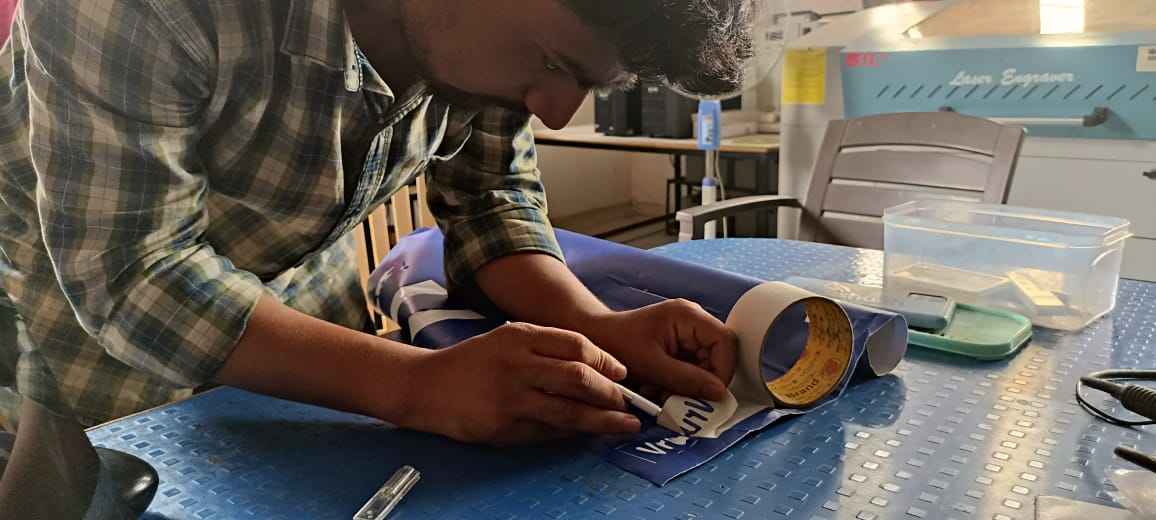
taking stiker on masking tape.
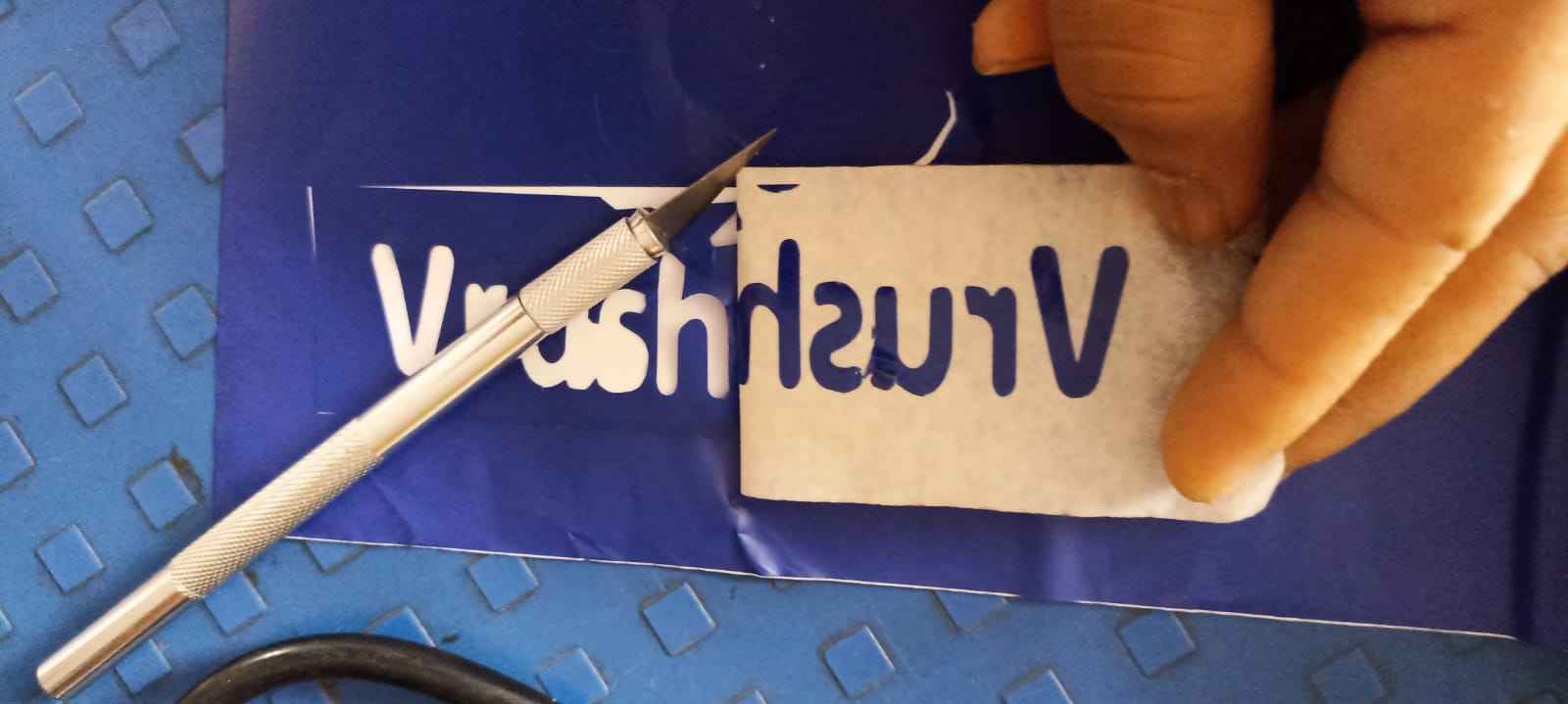
steker on masking tape.
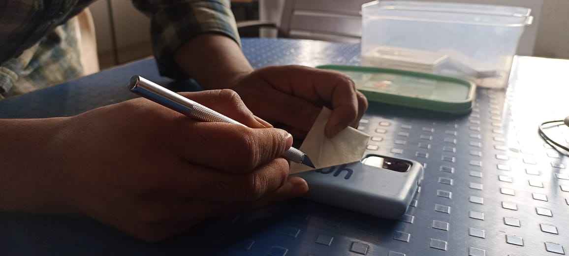
Appling skiker on mobile cover.
Final hero shorts:
This is the final hero shorts of how I stick the stickers on my mobile cover .
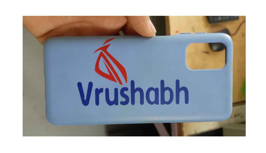
my mobile cover with new look.