The task list for this week:
- Group assignment:
- Compare as many tool options as possible.
- Individual assignments.
- Write an application that interfaces a user with an input and/or output device that you made.
Group assignment:
In this week's group assignment. We learned about various Interface and Application Programming that including understanding different tools for developing applications and interface programming. We also learned how to use these tools, their features and their purposes. We also try to make some applications using application tools like MIT app Inventor, Processing, etc.
Individual assignments:
MIT App Inventor:
What is App Inventor?
I saw it for the first time using my younger sister 3 years ago. At that time I was only aware of making Mobile applications with the help of android studio. But this was amazing for beginners to get a feel of making an application. The App Inventor project began at Google in 2007 when Prof. Hal Abelson of MIT went on sabbatical at Google Labs. The project leads were inspired by increased interest in educational blocks programming languages. App Inventor lets you develop applications for Android phones using a web browser and either the connected phone or emulator. The App Inventor servers store your work and help you keep track of your projects.its amazing 😀
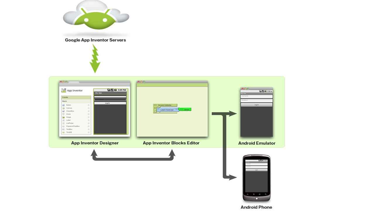
How it works.
To reab more about MIT app inventors visit their Page by clicking here.

App Designing:
App development Is a two-stage work. One has to do front-end programming for creating UI (user interface) and back-end programming to run the application the way it has to. In the MIT app inventor programming environment, They make it very simple by creating a very easy graphical interface both for the Designing section(front end )and Block coding section(Back end). I start with the front end of the designing section that I refer to this document on their website which helps me in designing an app.
1. To start with the Mit app I first visit on there website and clock on creating app button. To start to build the application.
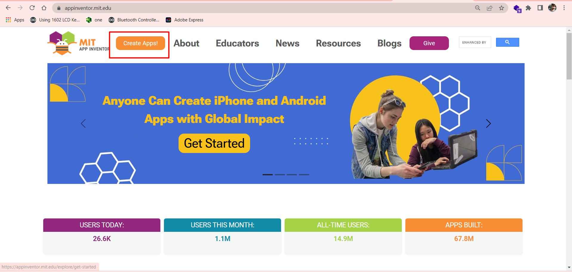
MIT app inventer home page.
2. After that I create the new project by clicking Start new project and giving a name to my Project.
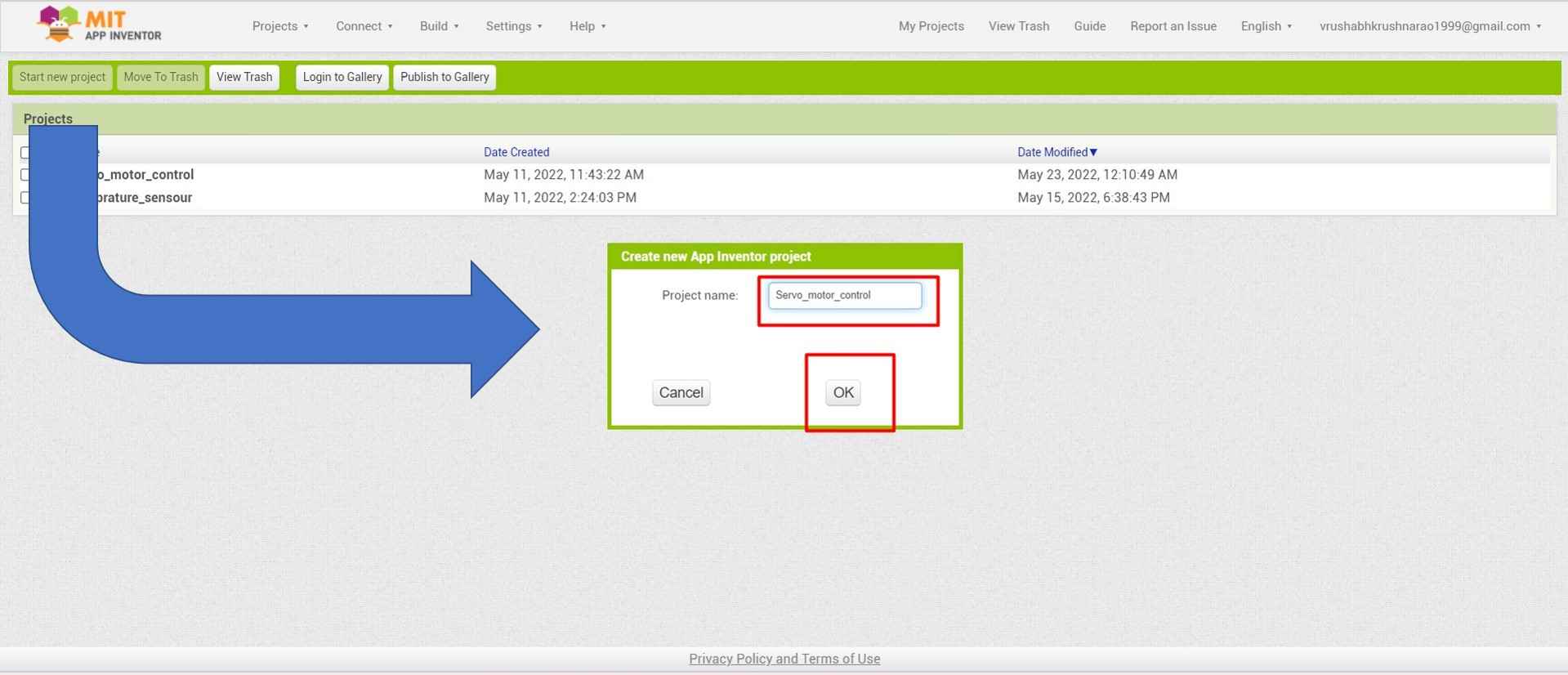
Creating new project.
Front-end Design:
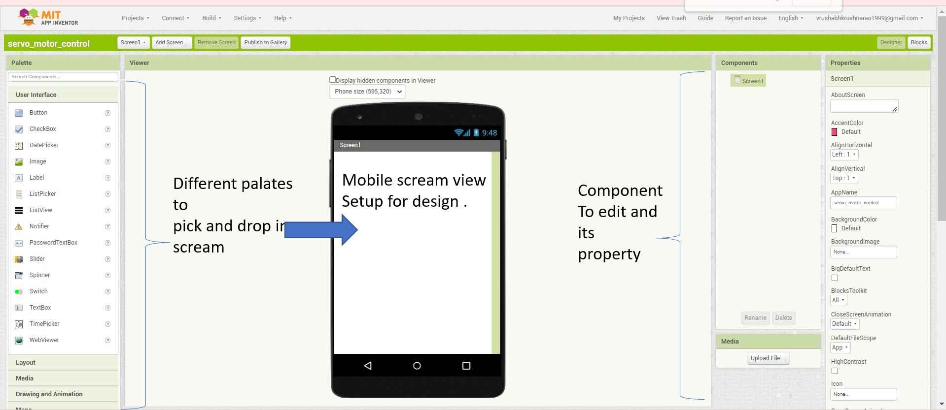
3. Here is a new fresh app development environment window open. It has 4 sections Palet where I found all the components I need to build my front end. Click here to read more here.
.
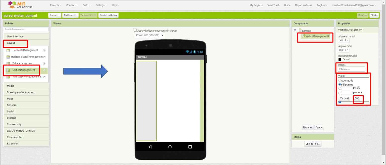
4. I start with the layout. I pick the vertical layout and scale up it fully to the entire screen as you can see in the picture.
.
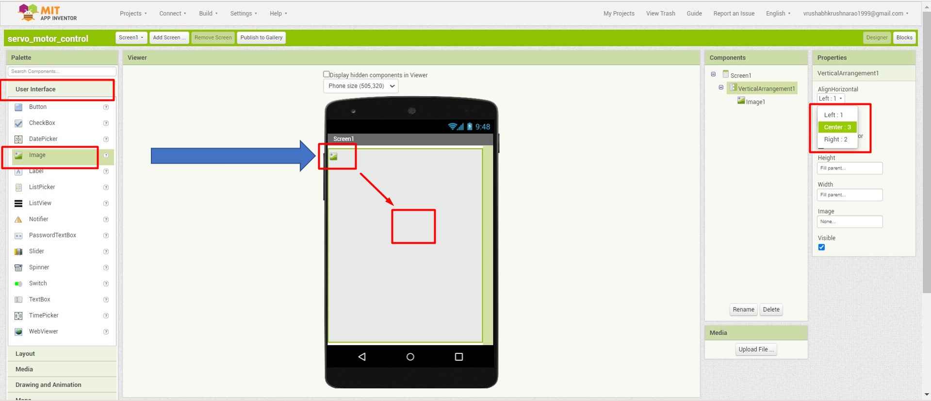
5. Then I drag and drop an image palate from User Interface. and make it At the centre of the screen through the properties tab.
.
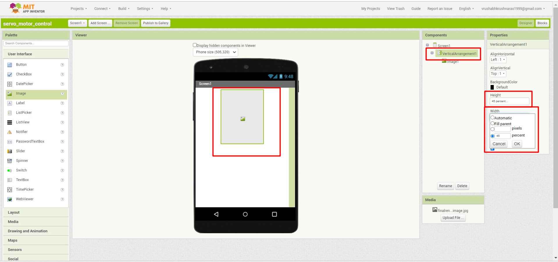
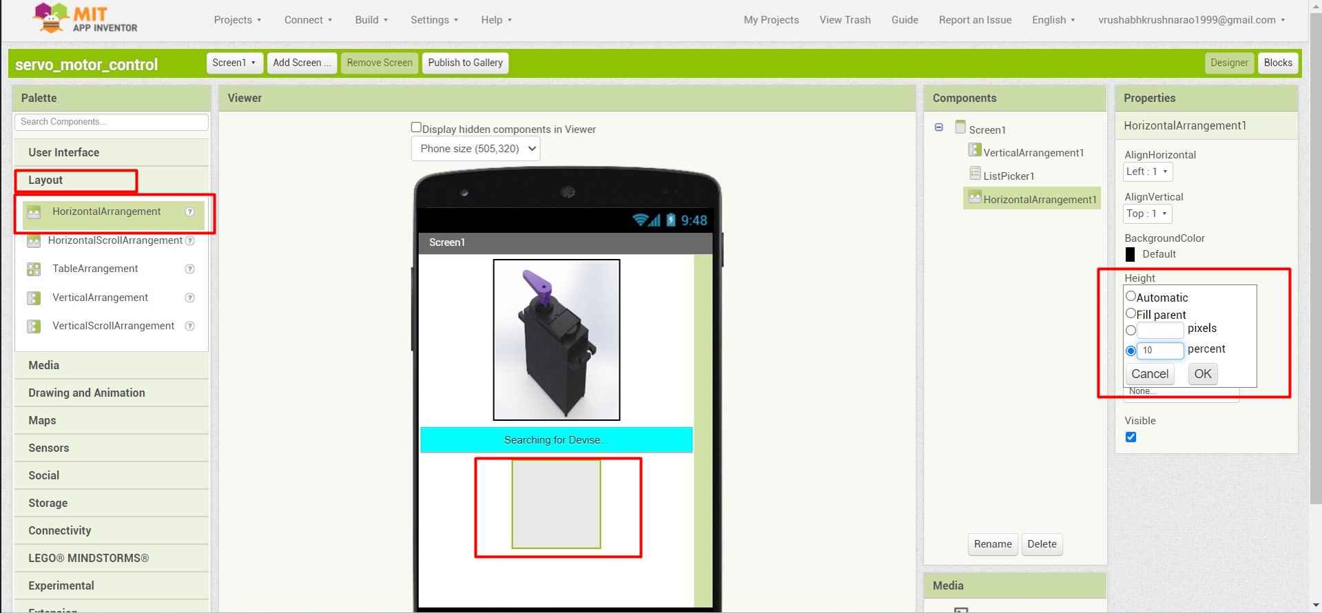
6. I define the Image size by defining the layout of the image as shown.
.
7. And then Upload a rendered image of a servo motor from my last assignments.
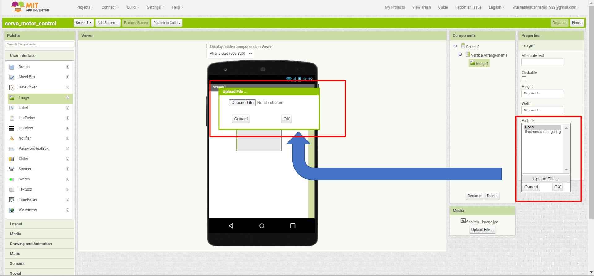
.
8. Then for listing the Bluetooth devices. I add a list picker and resize it with a width of 10% suitable for to screen.
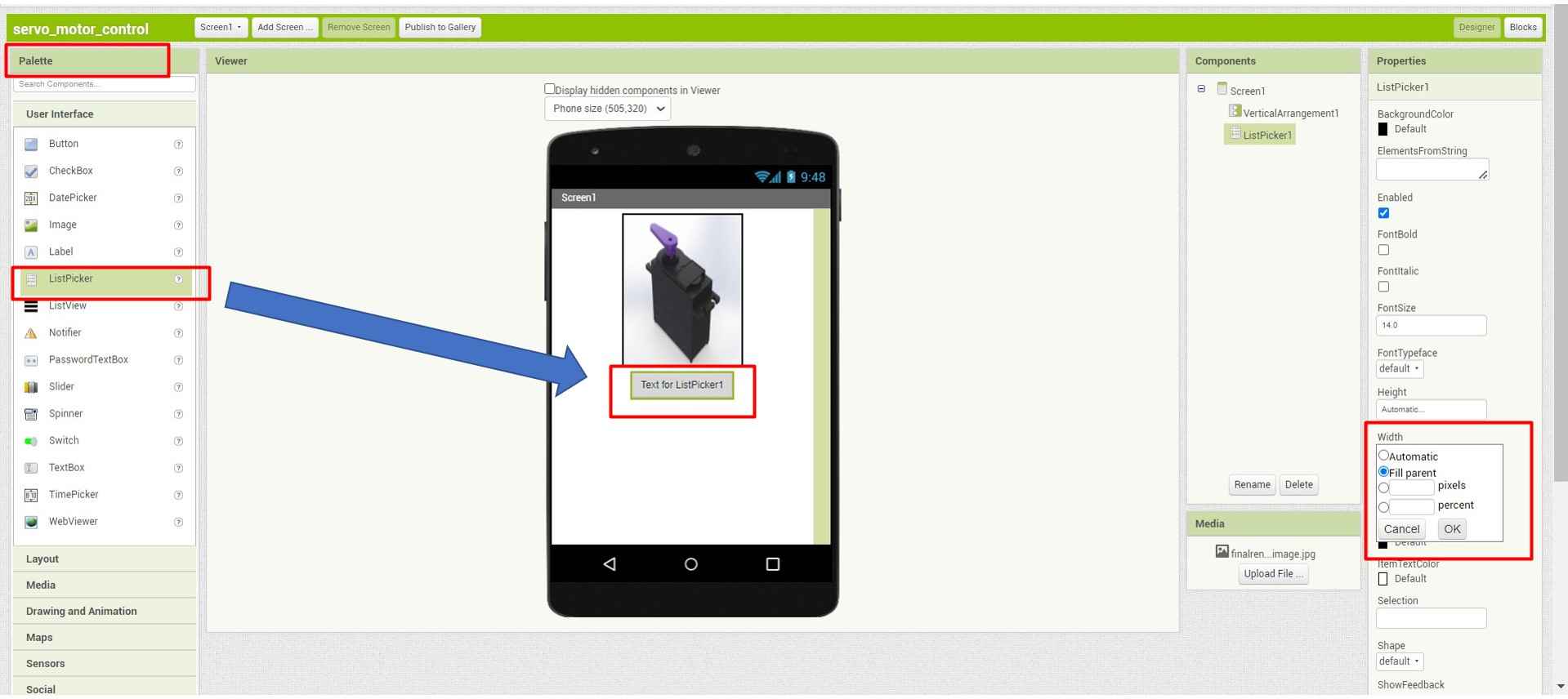
.
9. I named it Searching for a new device. So that users can easily Identify its functionality of finding the device.
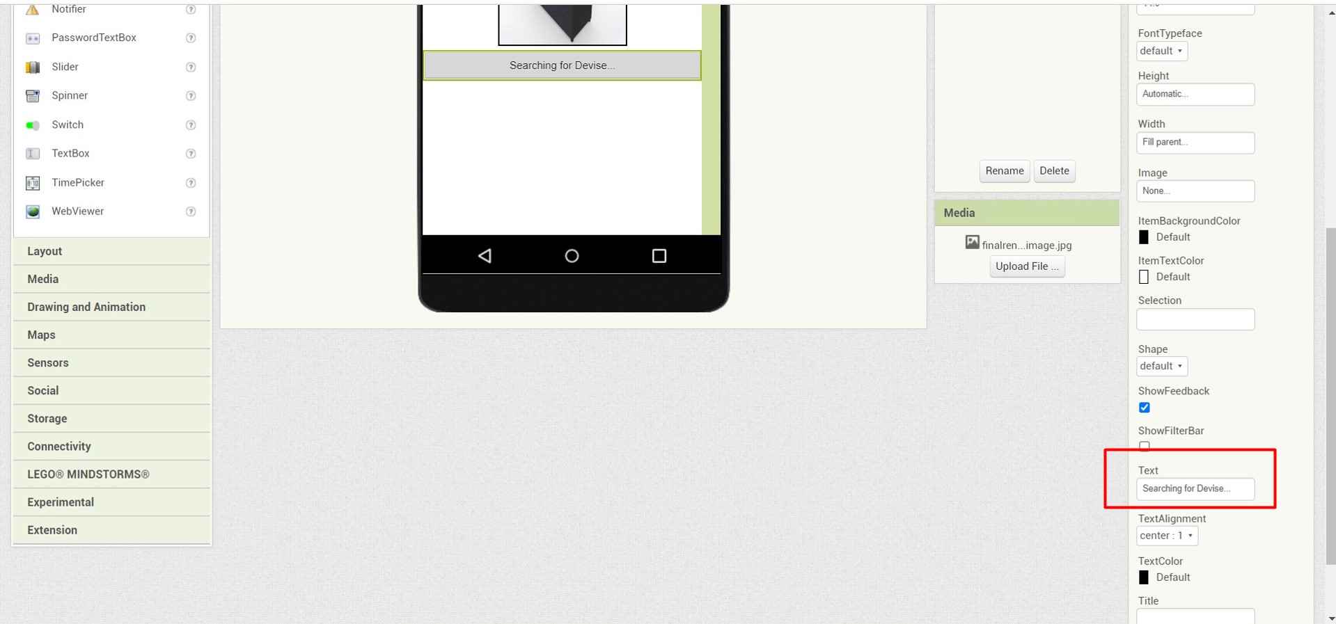
.
10. Then I use to give it a nice looking colour through Background colour in the properties tab.
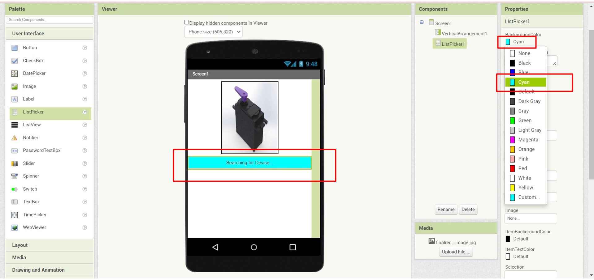
.
11. Then I use a horizontal arrangement to leave some space after the slider.
.
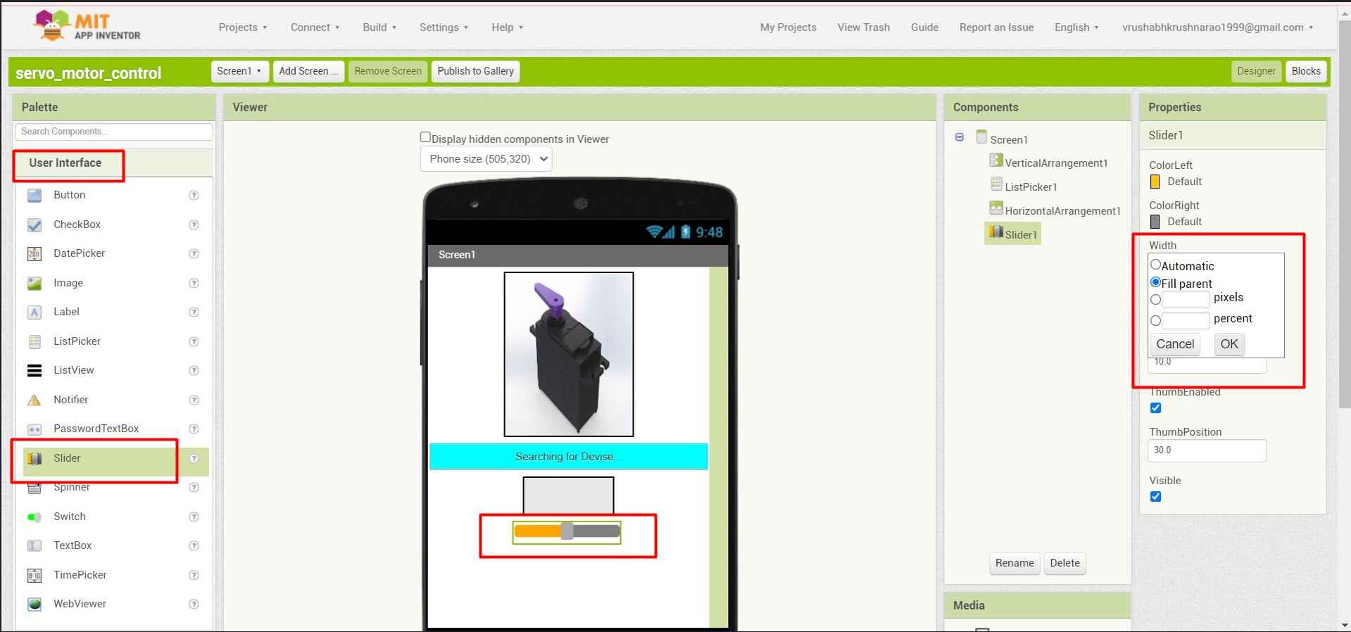
12. For controlling the Servo motor through Interface I pick up a Sliding component and make it its full length to make a nice UX(User experience) design.
.
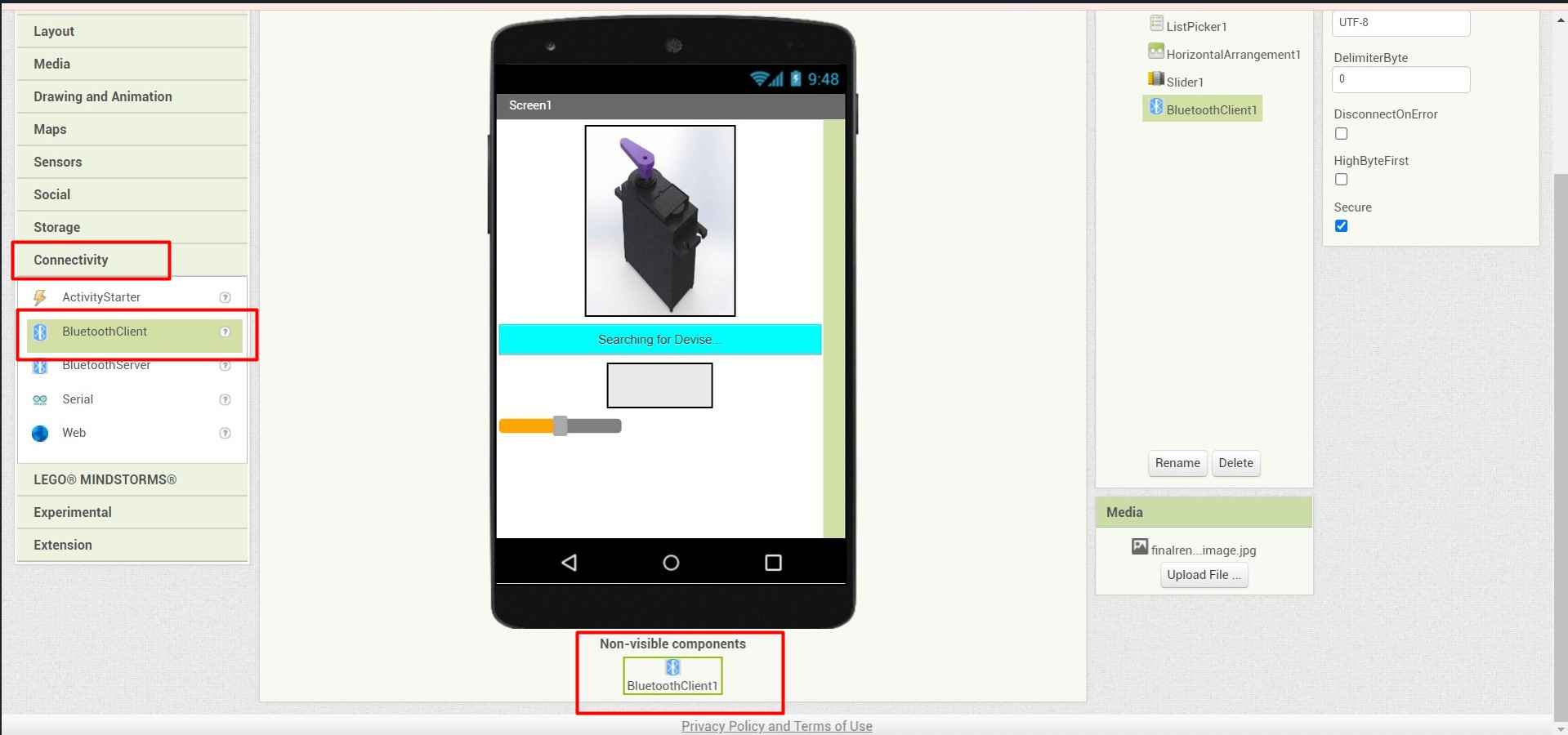
13. To make connection with other devices through this Interface I added a Bluetooth component to the design.
.
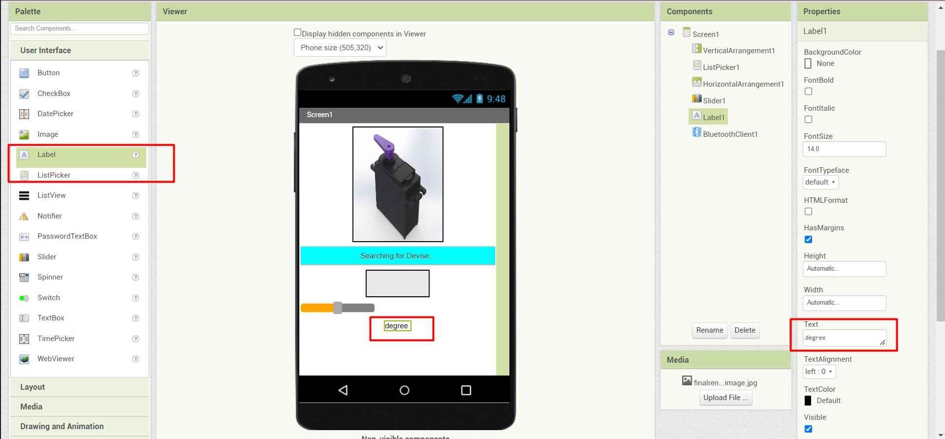
14. To provide the current angle of revolution of the Servo motor shaft. I provide a Lable tab just below the slider and name its degree. Because it will show the no. of degree the servo will revolve.
.
15. Then I provide another HorizontalArrangement at the very bottom of the screen to provide the Space for buttons.
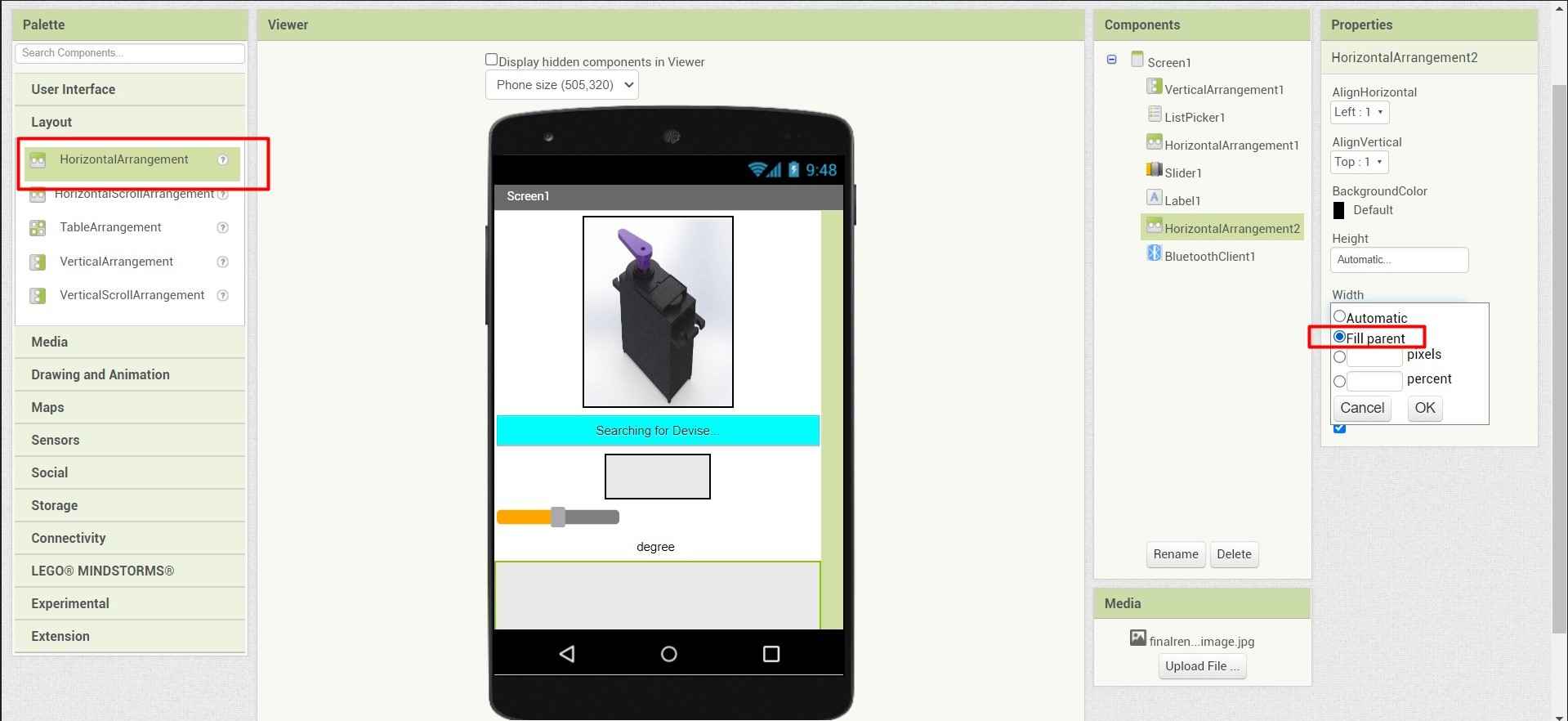
.
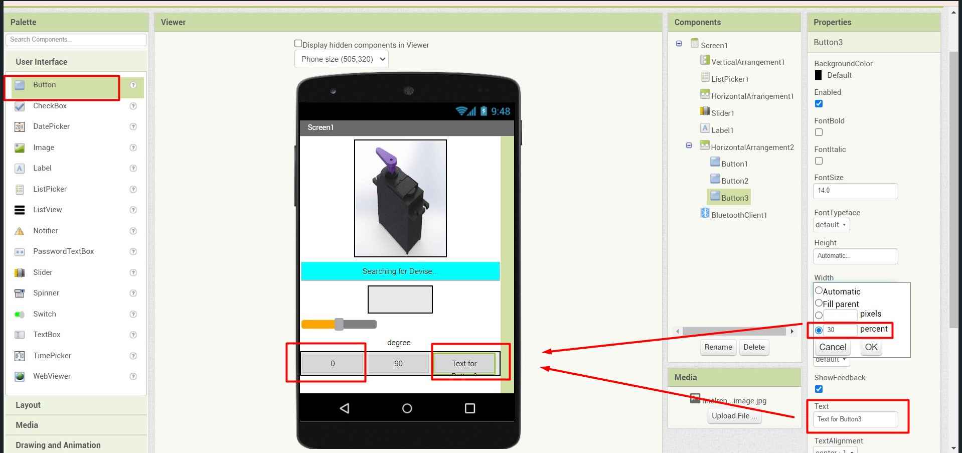
16. I decided to add 3 buttons for moving servo at 0 degrees 90 degrees and 180 degrees respectively. I also use the property section to make them in place by resizing their size and also providing the buttons and their nomenclator respectively.
.
17.I rename the buttons .
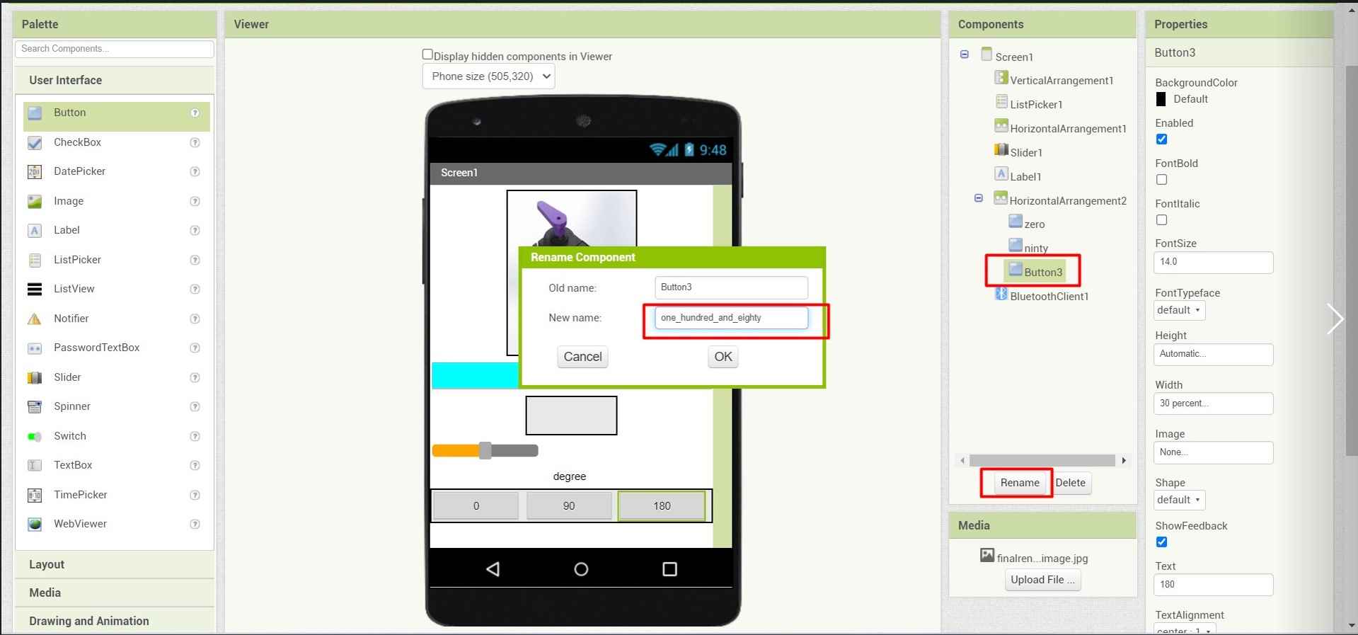
.
18.I also provide colours in them for easy identification.
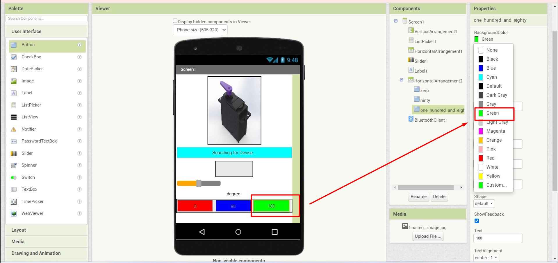
.
And here I endup with my front-end design.
Back-end Block Coding:
For designing the back end for the above UI .MIT media app provides the blocks language platform. where Built-in blocks are available regardless of which components are in the project. In addition to these language blocks, each component in the project has its own set of blocks specific to its own events, methods, and properties. To know more about Built-In Blocks in MIT app inventor Blocks Editor click here.
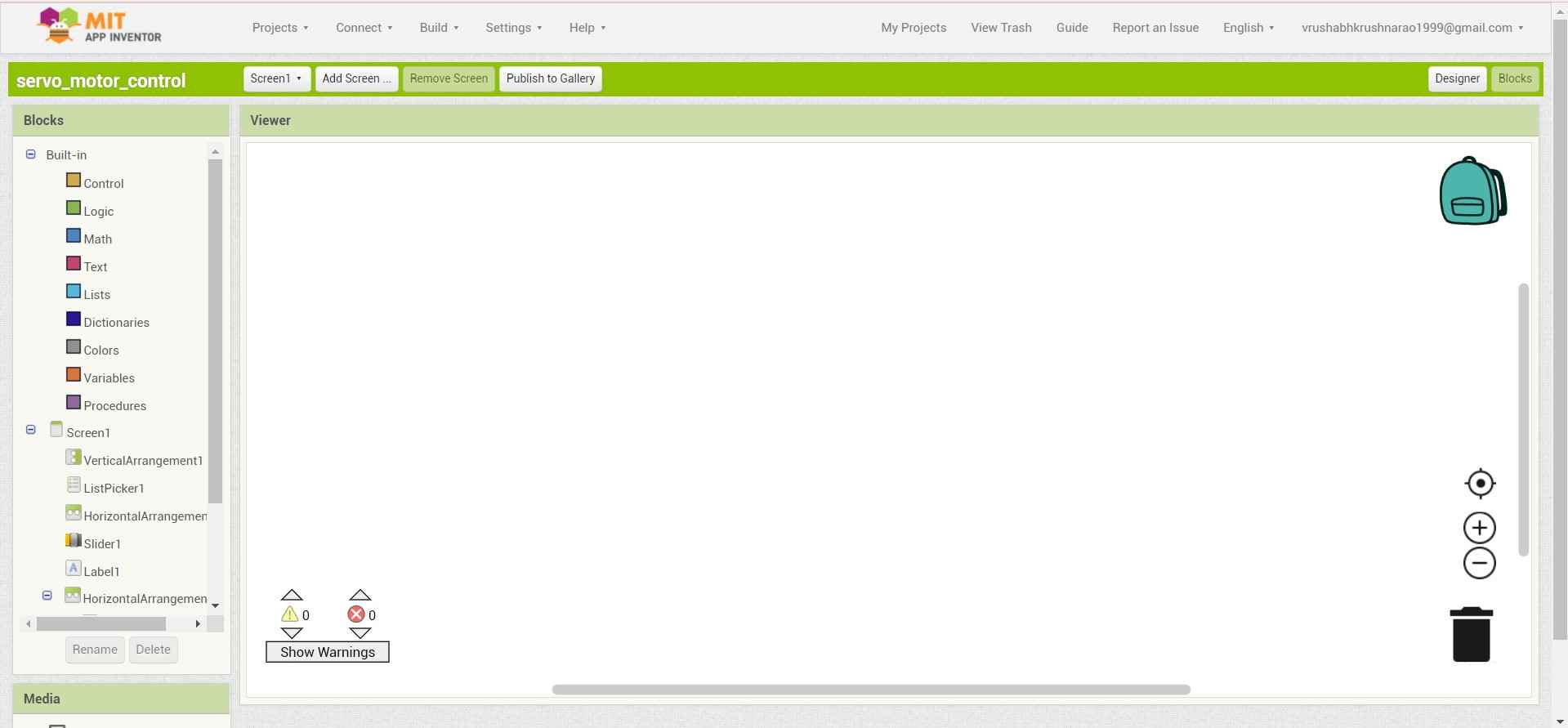
1. To start with back-end Programing. I click on the right-top left button (blocks) at the corner of the design window.which will open a new window dedicate to back-end Programing . It consists of two sections where in one section you are provided with Blocks including various functions in graphical block format and programing space to arrange them in secuence.
.
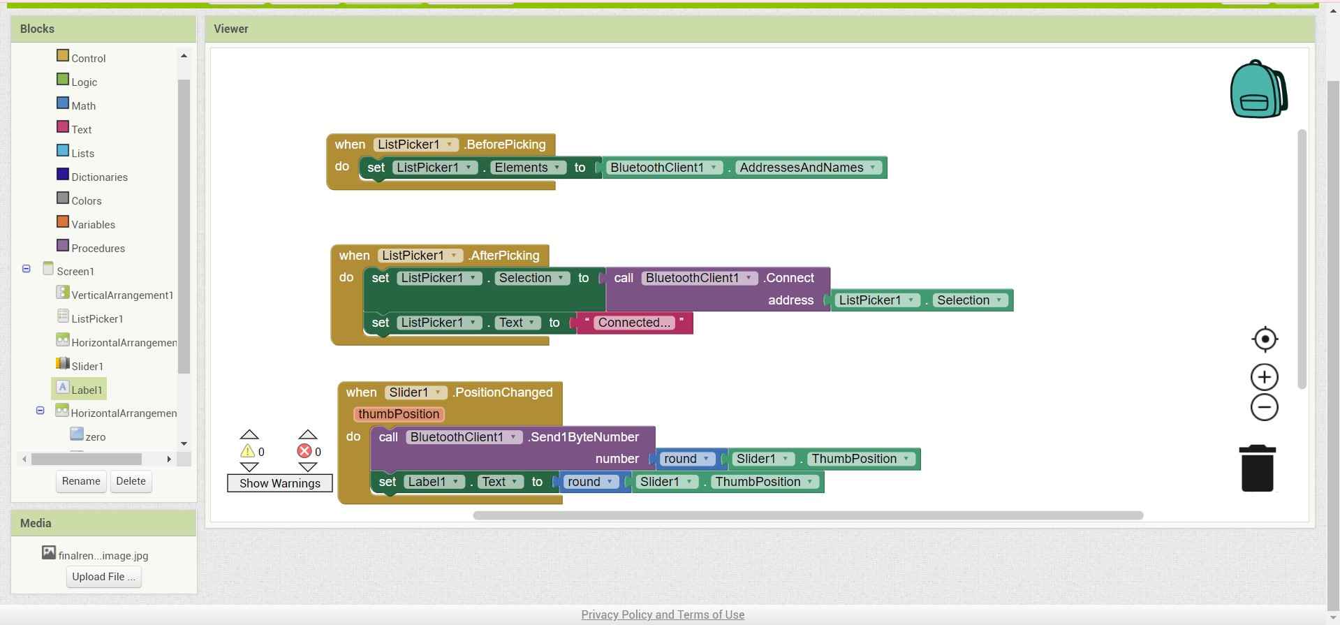
2. I follow the sequence that I follow in the design section and start with a list-picker code function. which I will need to pick a Bluetooth devise.
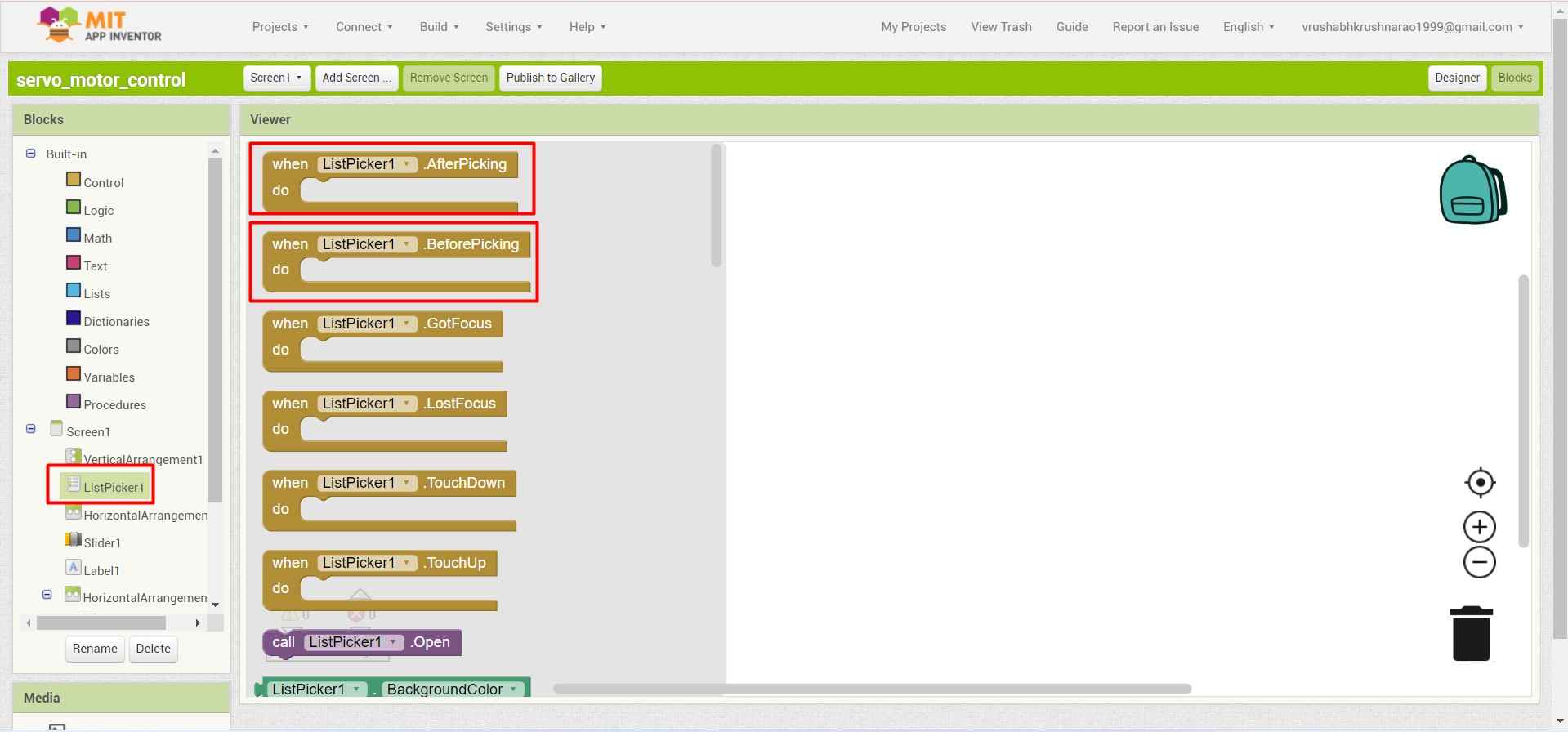
.
3. Then pick a block to specify the no. of devices(Elements) available to connect.
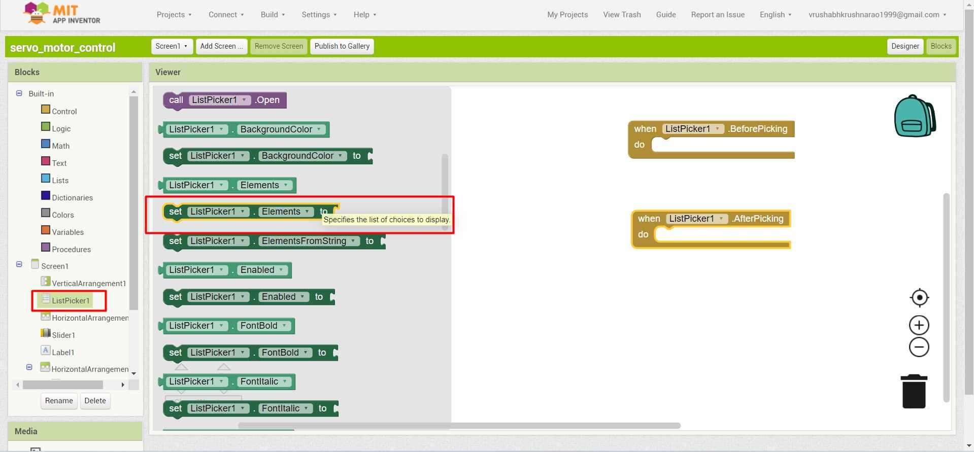
.
4. I came across an error and after hovering over it. I got this message .Which tries to mine that this is not enough to complete the logic.
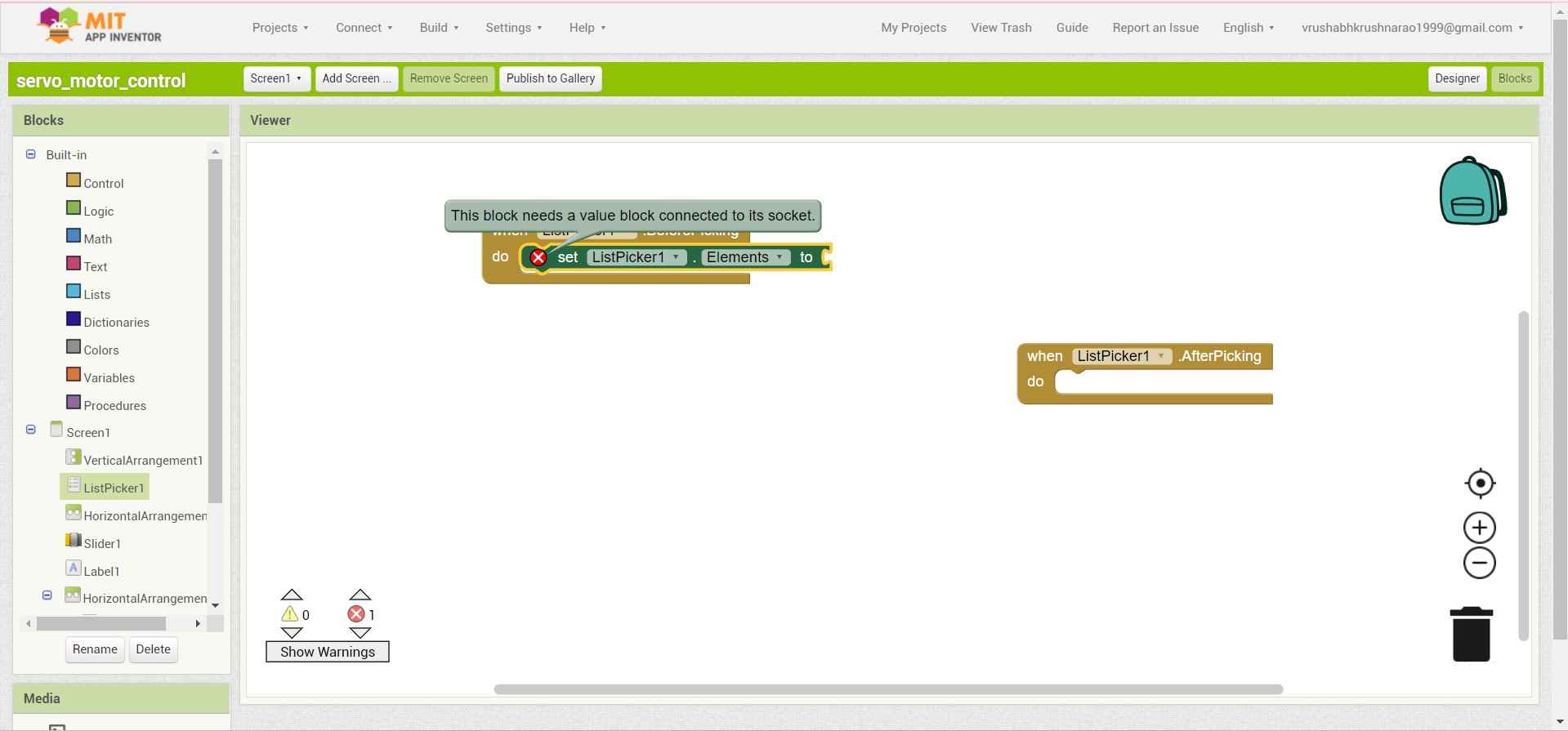
.
5. So I have to specify the Source and the type of element input to the list picker to display on the app.
.
6. I duplicate the functional blocks and attach them to the After picking condition.
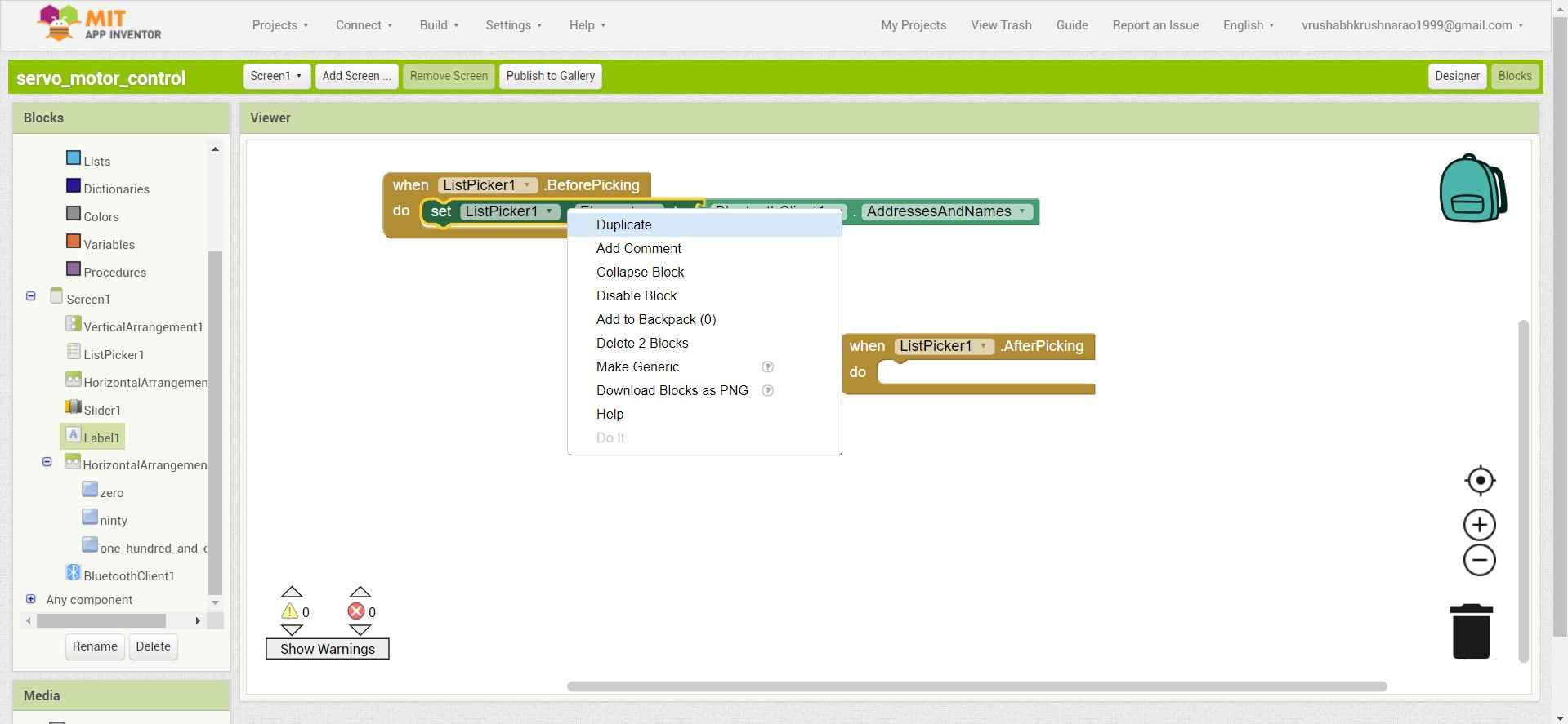
.
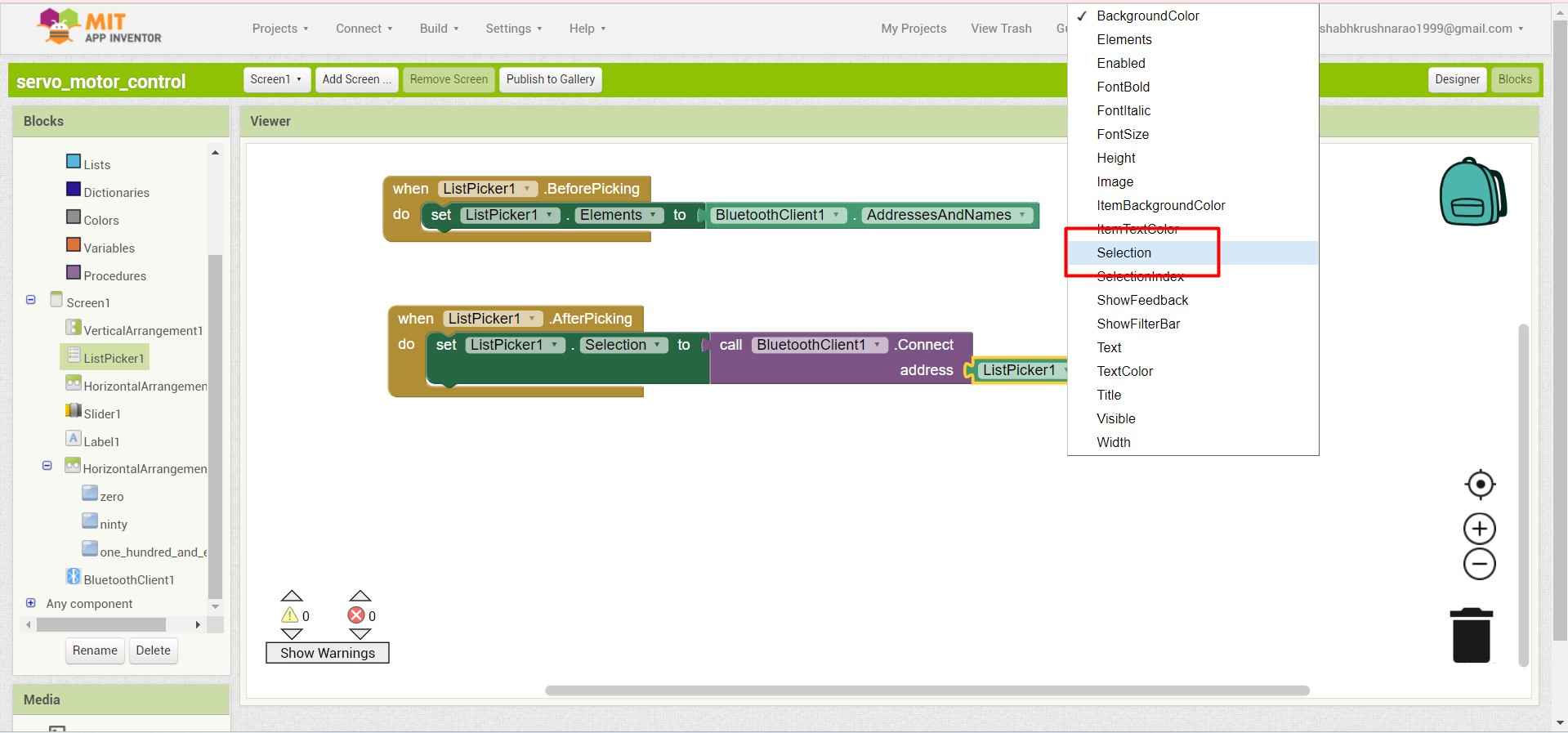
7.I change the Listpicer display from Elements to Selection.
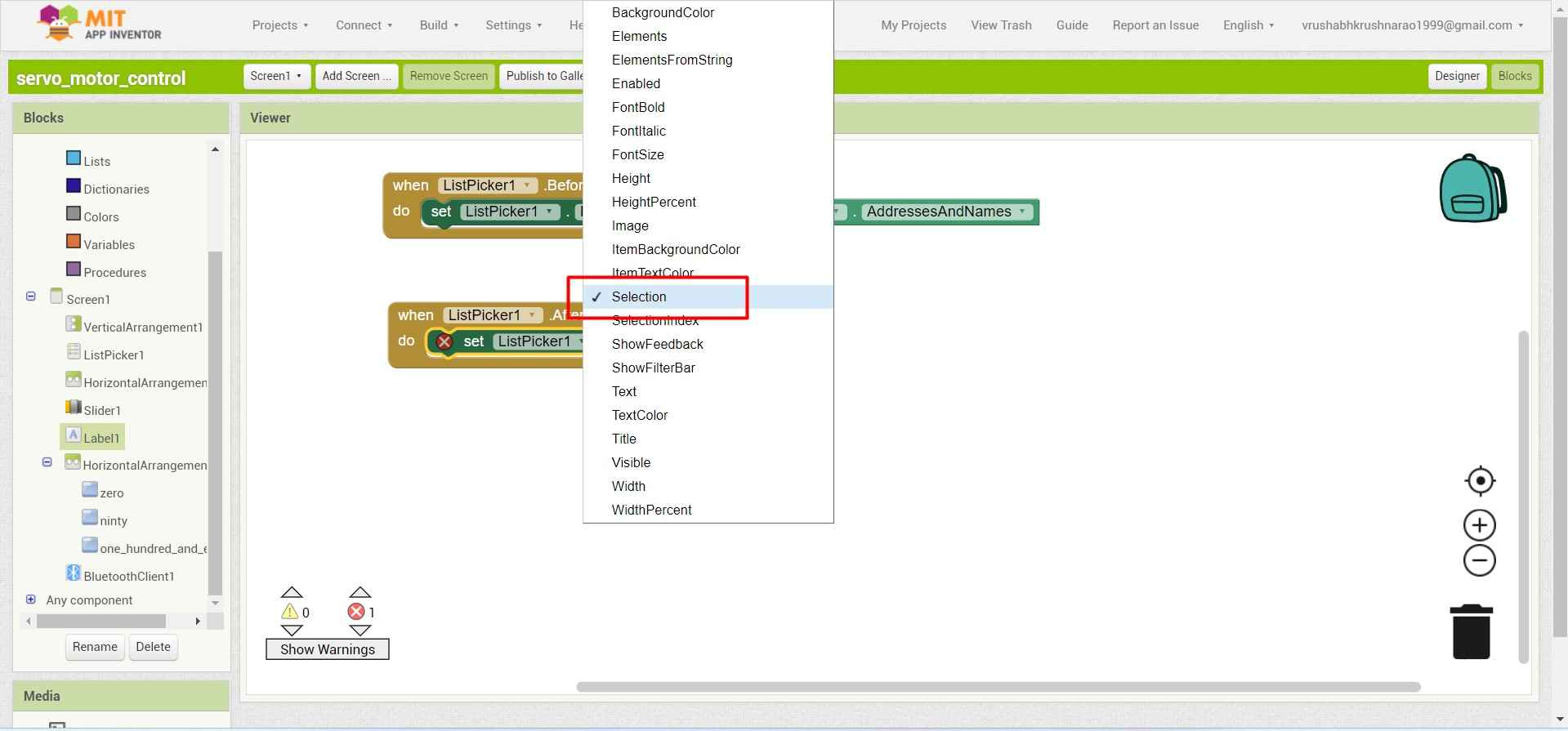
.
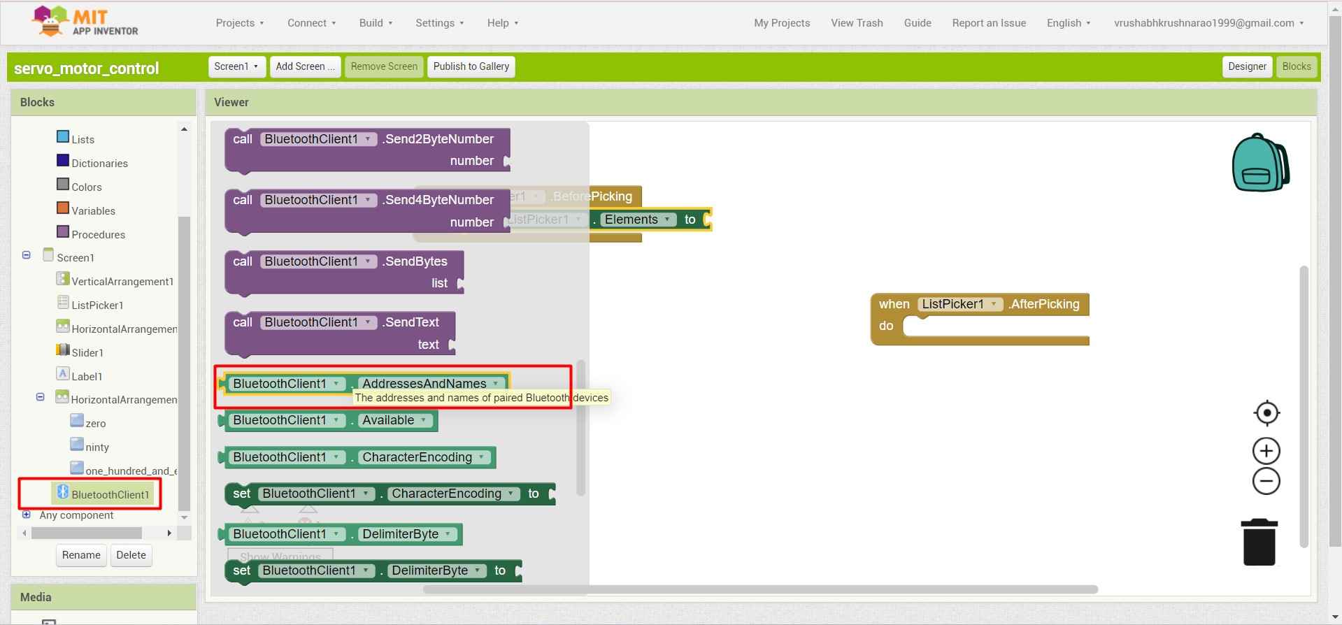
8.I add a blutooth function for communicate obetween application with other blutooth devices.
.
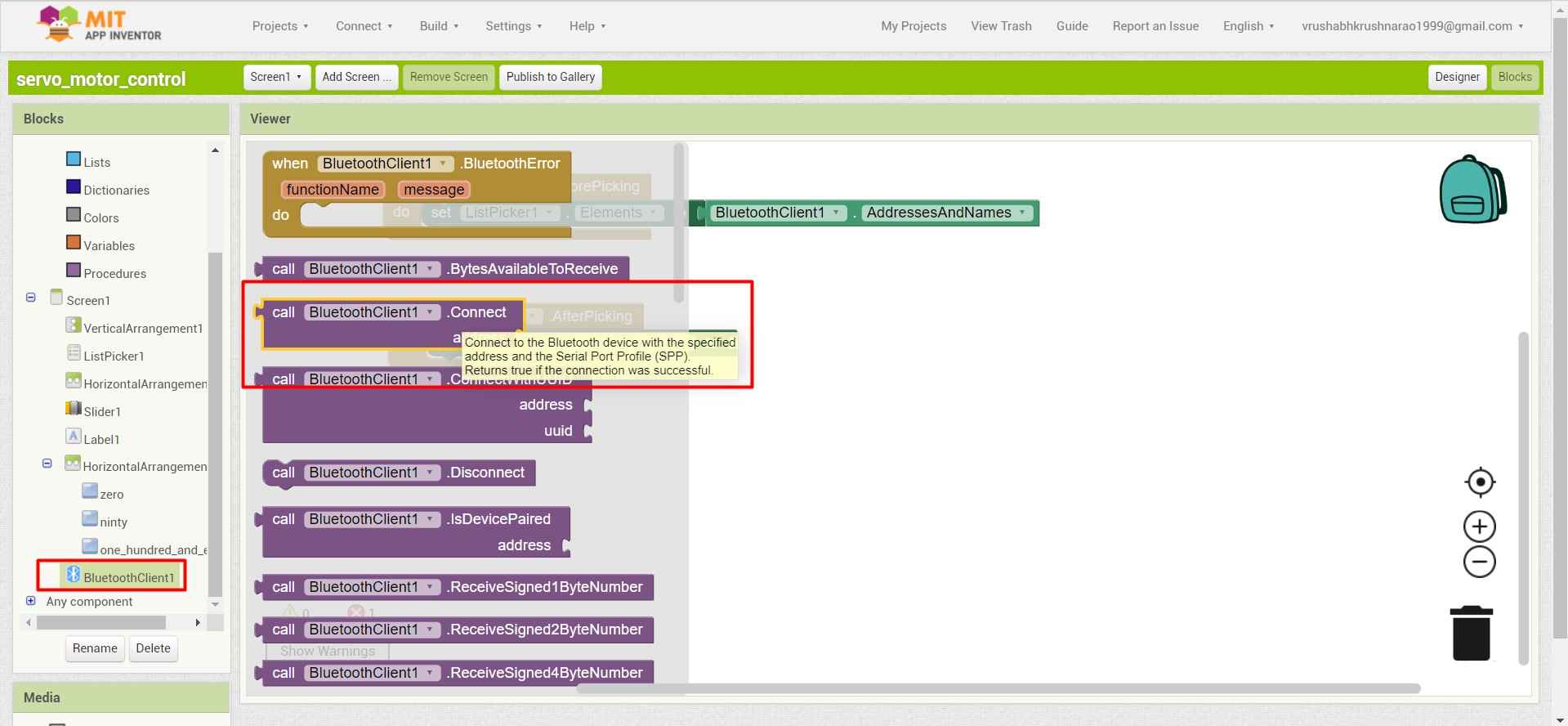
9.For connecting the bluetooth devise .I require a listpicer function.
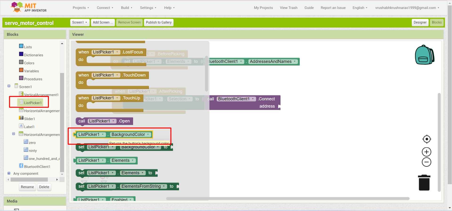
.
10.I pick a set listpicker block and change it to selection .Which retarn the value from selected device to app.
.
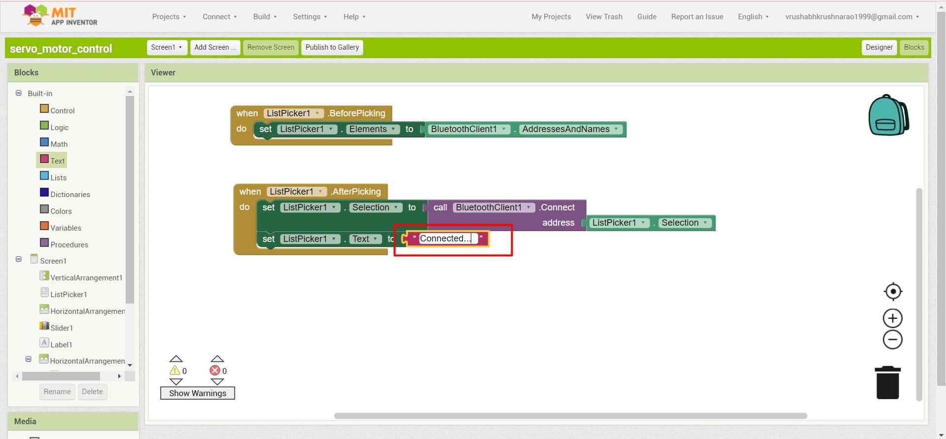
11.I added one more Listpicker block to add the text in it to show the device is connected.
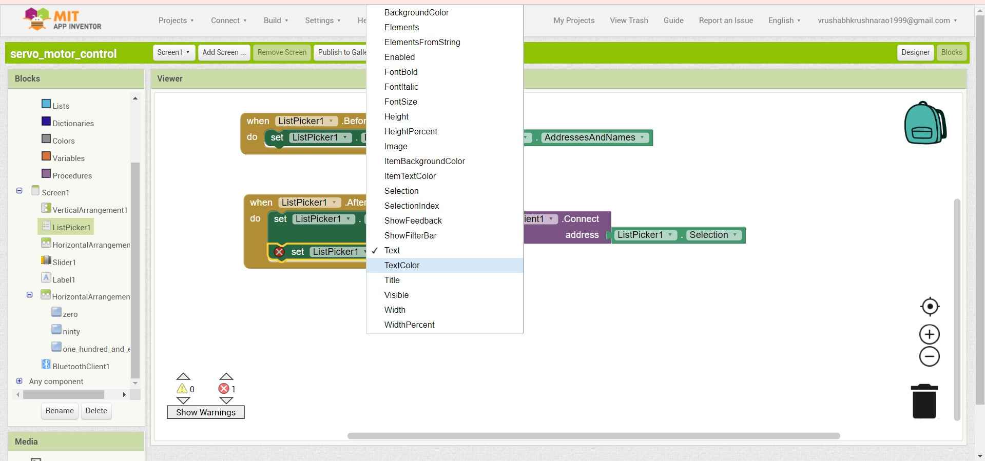
.
12.For that I pick up a text component.
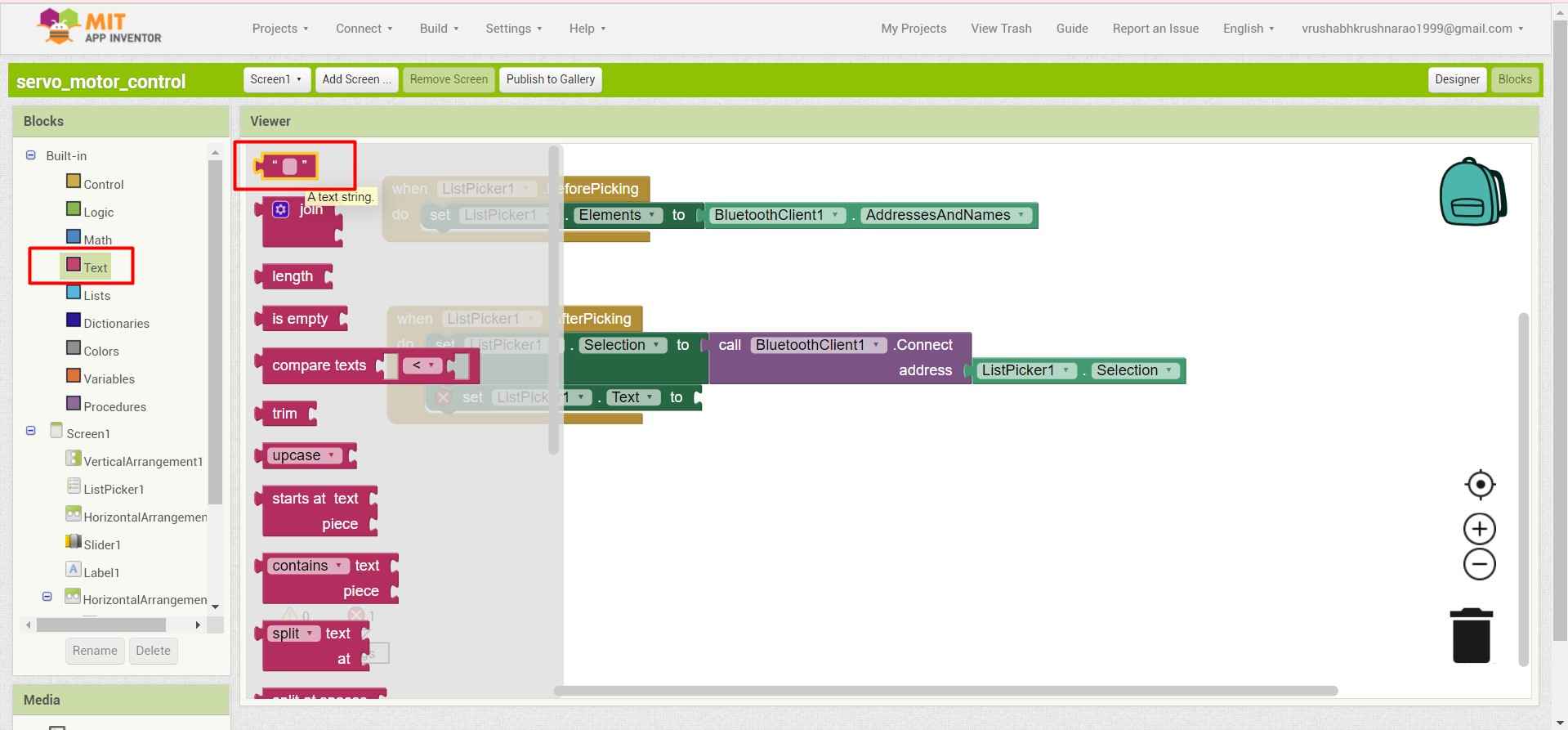
.
13.And print "connected.." on display after the device get paired with application.
.
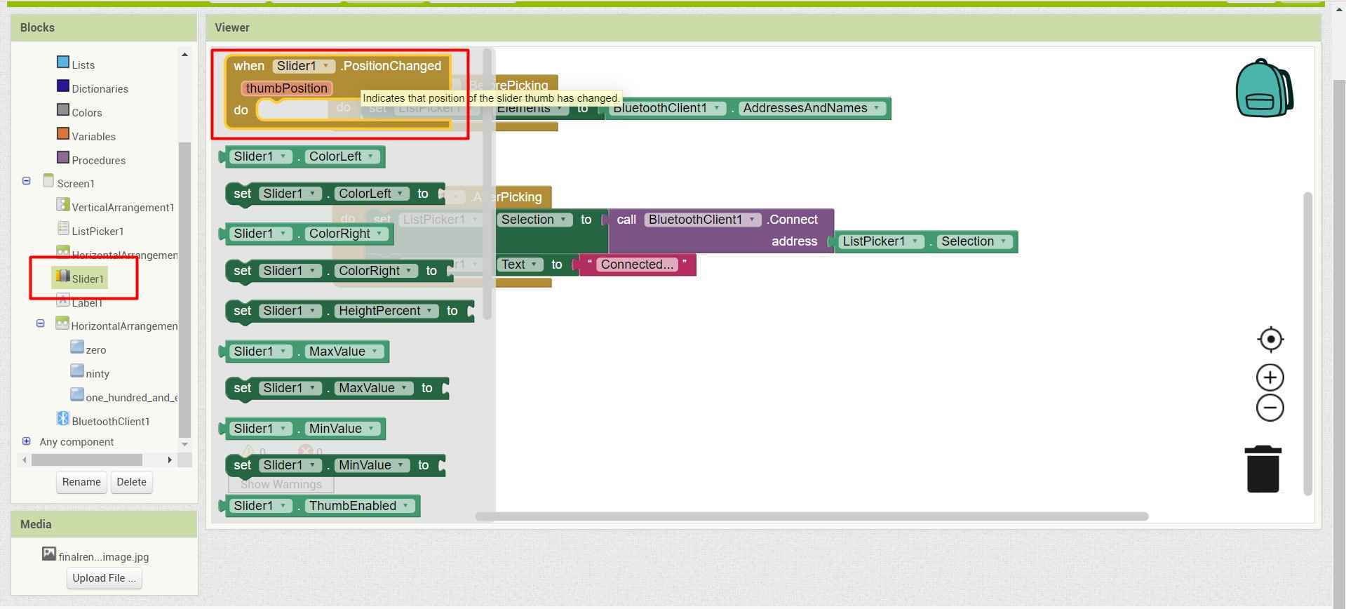
14.Now to generate data from slider input I add a contition function.
.
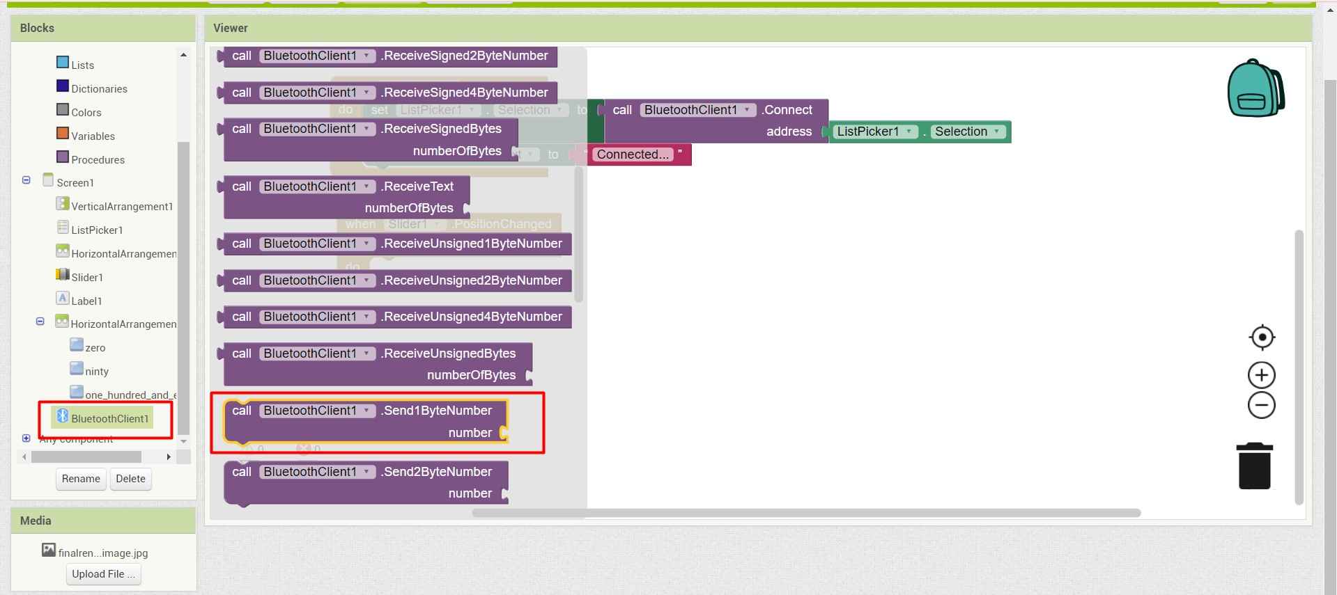
15.I also add the blutooth function to send this generated value to paired devices.
.
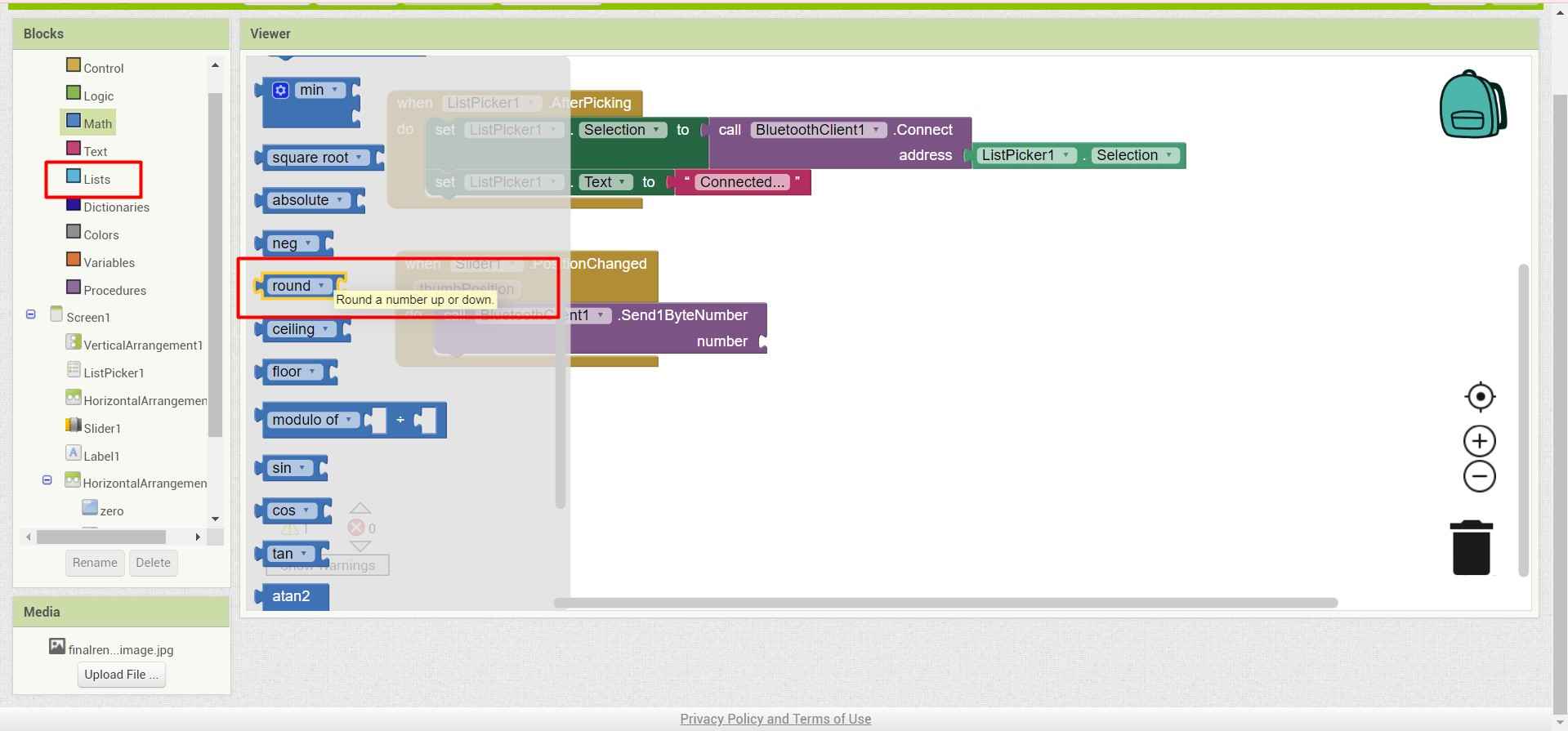
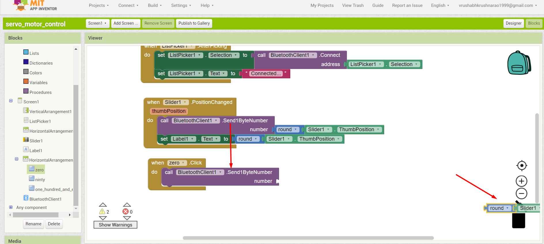
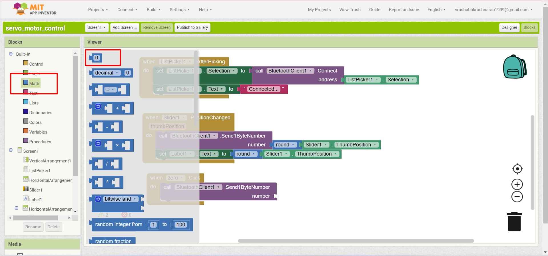
16.I use a roundup from maths function to filter the analog signal from the input slider interface.
.
17.And add a slider function to take input from user.
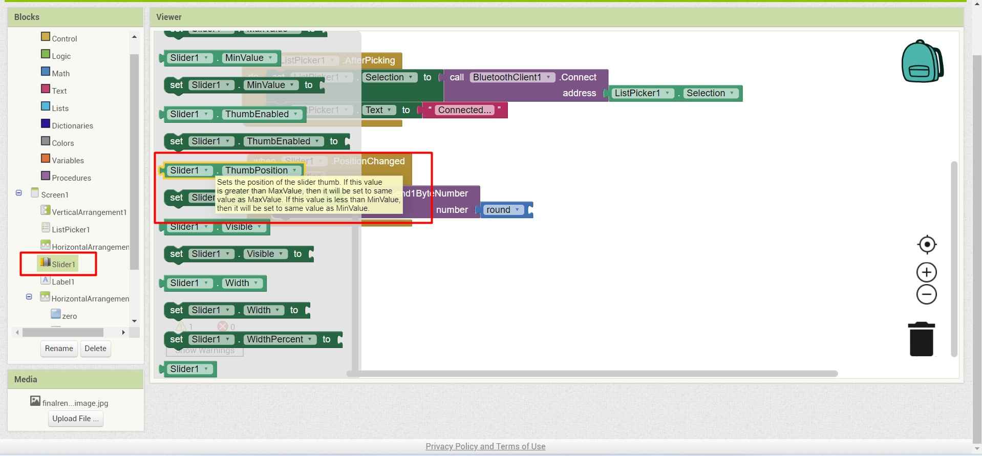
.
18.I also provide a lable block in front end design .which will show the current angle of motor with respect to position of slider .
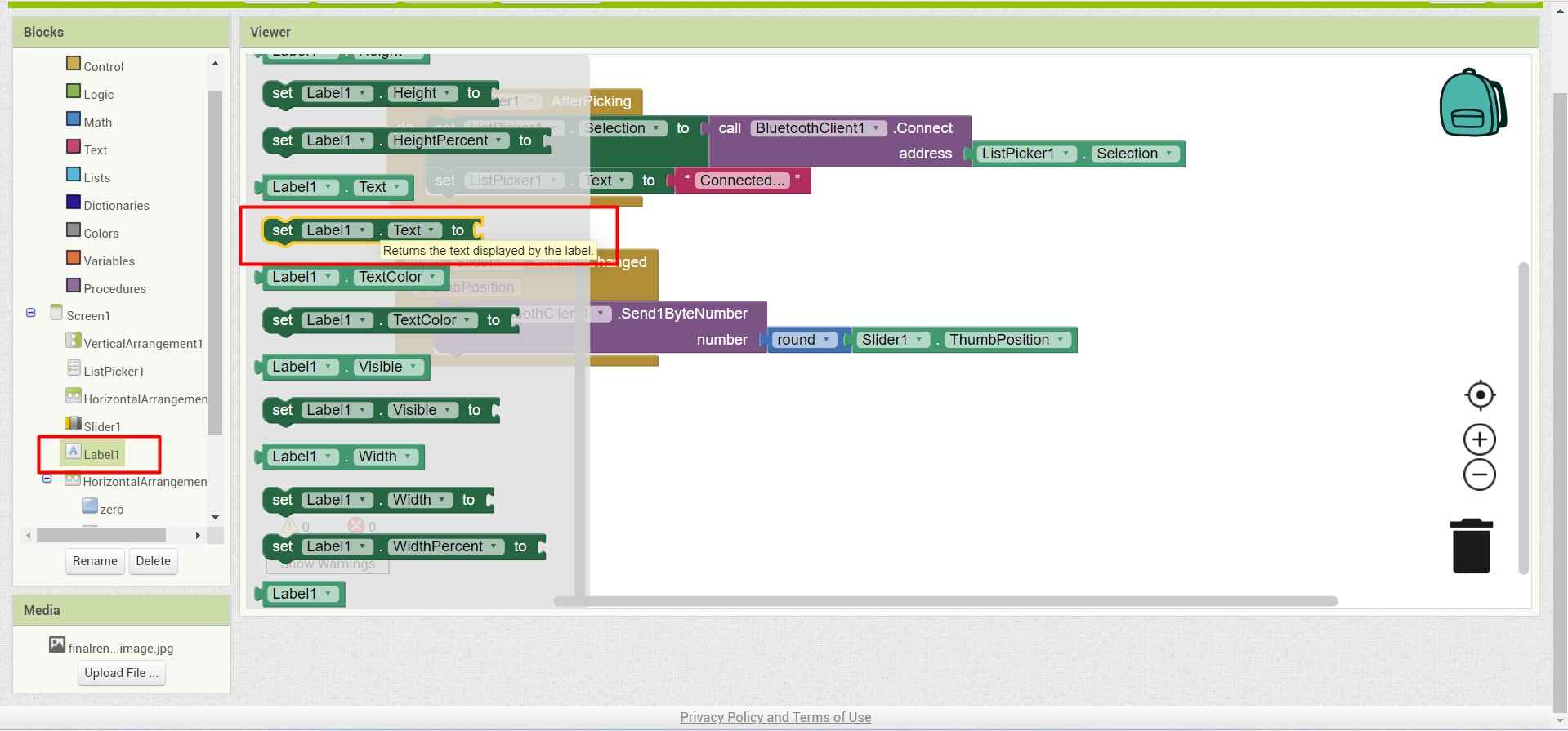
.
for that I pick a slider function which will provide the data from sliding input from ser
.
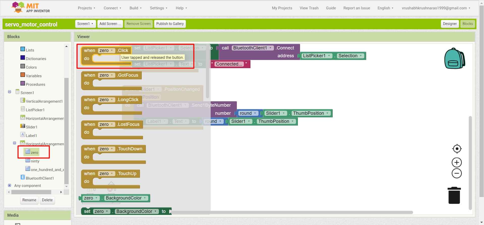
19.Finaly I have added some buttons at the bottom of the interface to directly assign the angle.For that I use the same while condition function as the slider.
.
20.Also I use the same bluetooth function to send the data .
.
21.And to assign the value I use integer blog to assign the angle for that button.
.
22.I did this for each of 3 buttons .
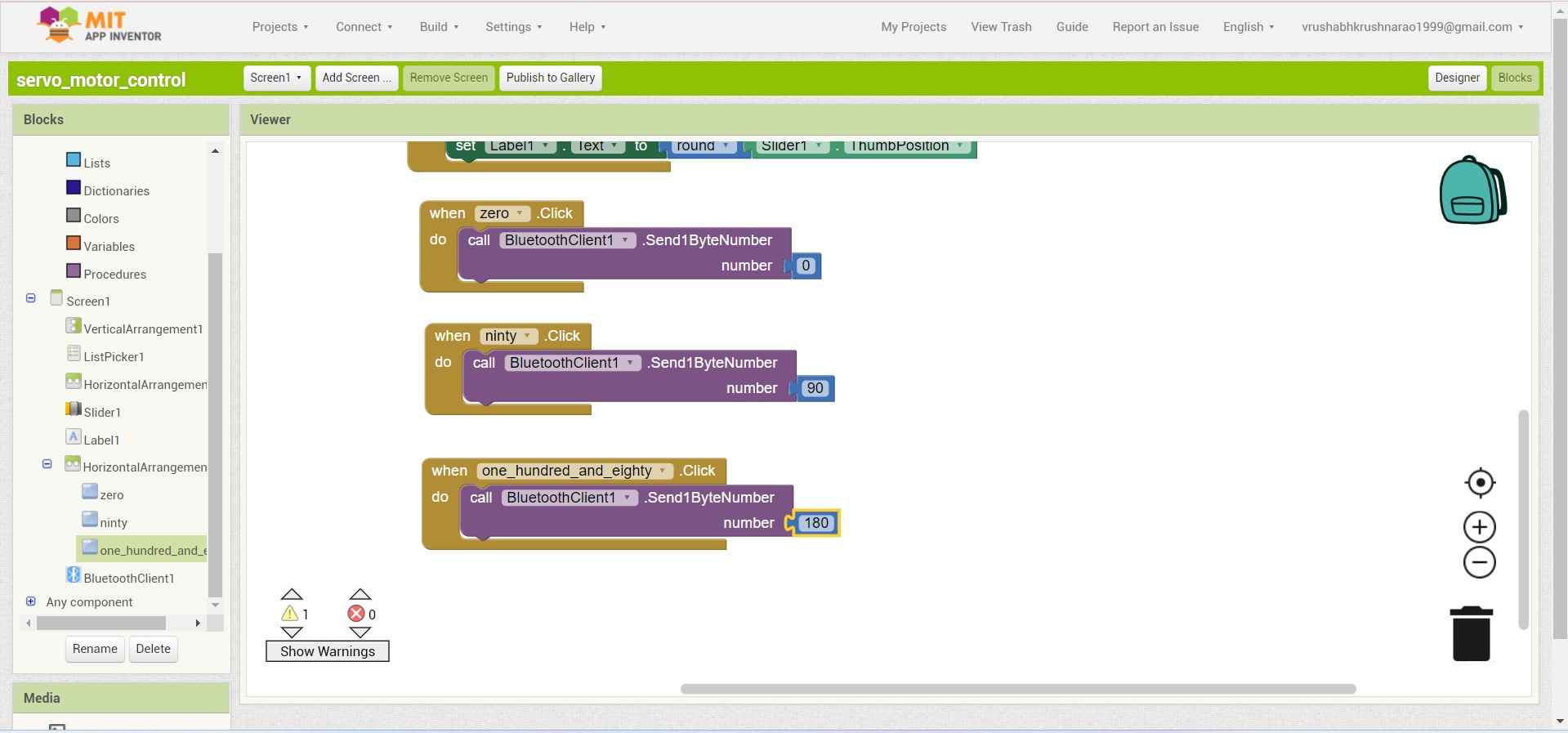
.
23.And here the back-end coding ends.
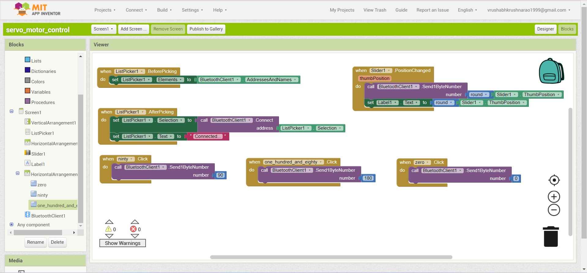
.
Installing the app in mobile:
For installing the app in mobile .You can Either download or open the app through browser .For that go to .
Build>Android Apk.
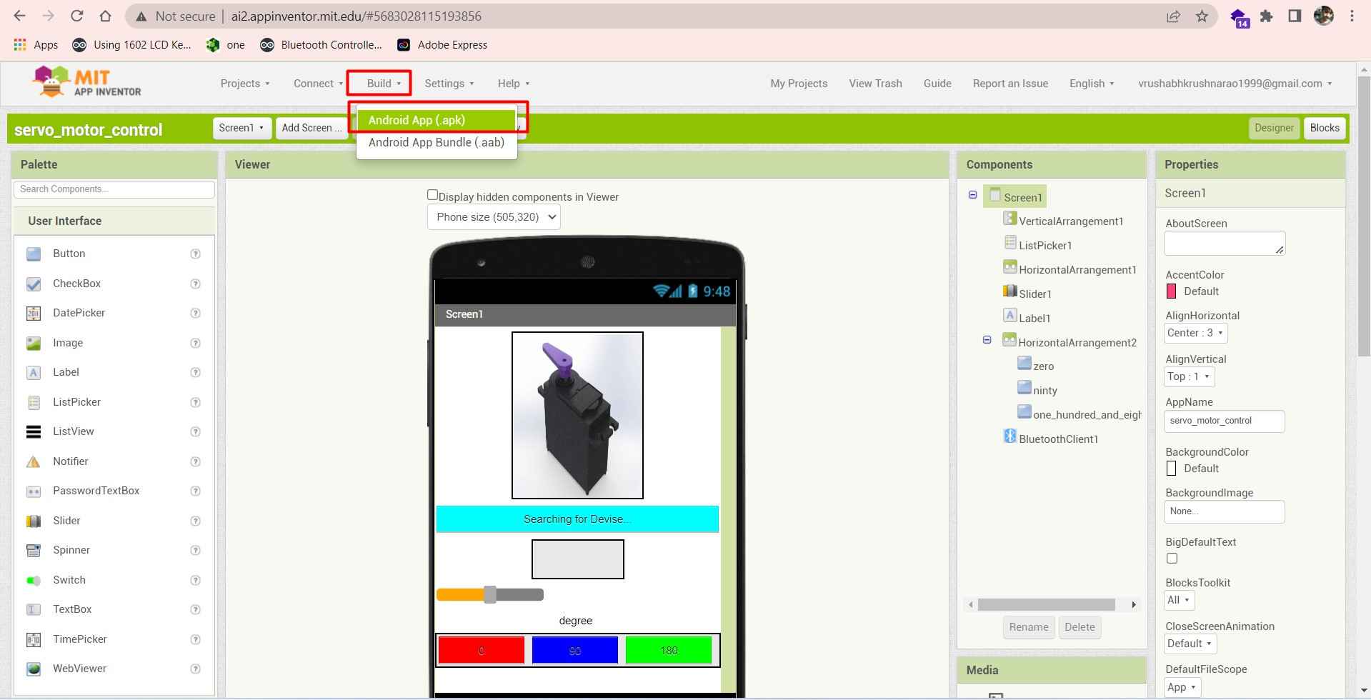
.
A window will open with an option of downloading the apk file or a QR scanner to open the application through brouser.I suggest downloading the apk file .In QR code one should need to scan the code from time to time to open the application.
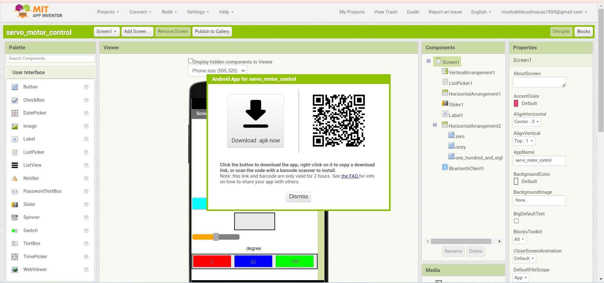
.
Arduino Code:
For operating the servo motor using the this app. I use my final project bord from week 13 , A MG995 Servo motor and a HC-05 Blutooth module.
Connections :
Servo motor : Vcc , Gnd, PWM(PA4 ~0Arduino pin).
HC-05 : Vcc, Gnd, Rx(PBO~7), Tx(PB1~6 Arduino pin).
I use SoftwereSerial.h Libery to Define the Rx and Tx pin in ATtiny1614 microcontrol in my bord.
I write this costum code for my Board for controlling the Servo motor.
Code to controle Servo motor using blutooth module HC-05 .
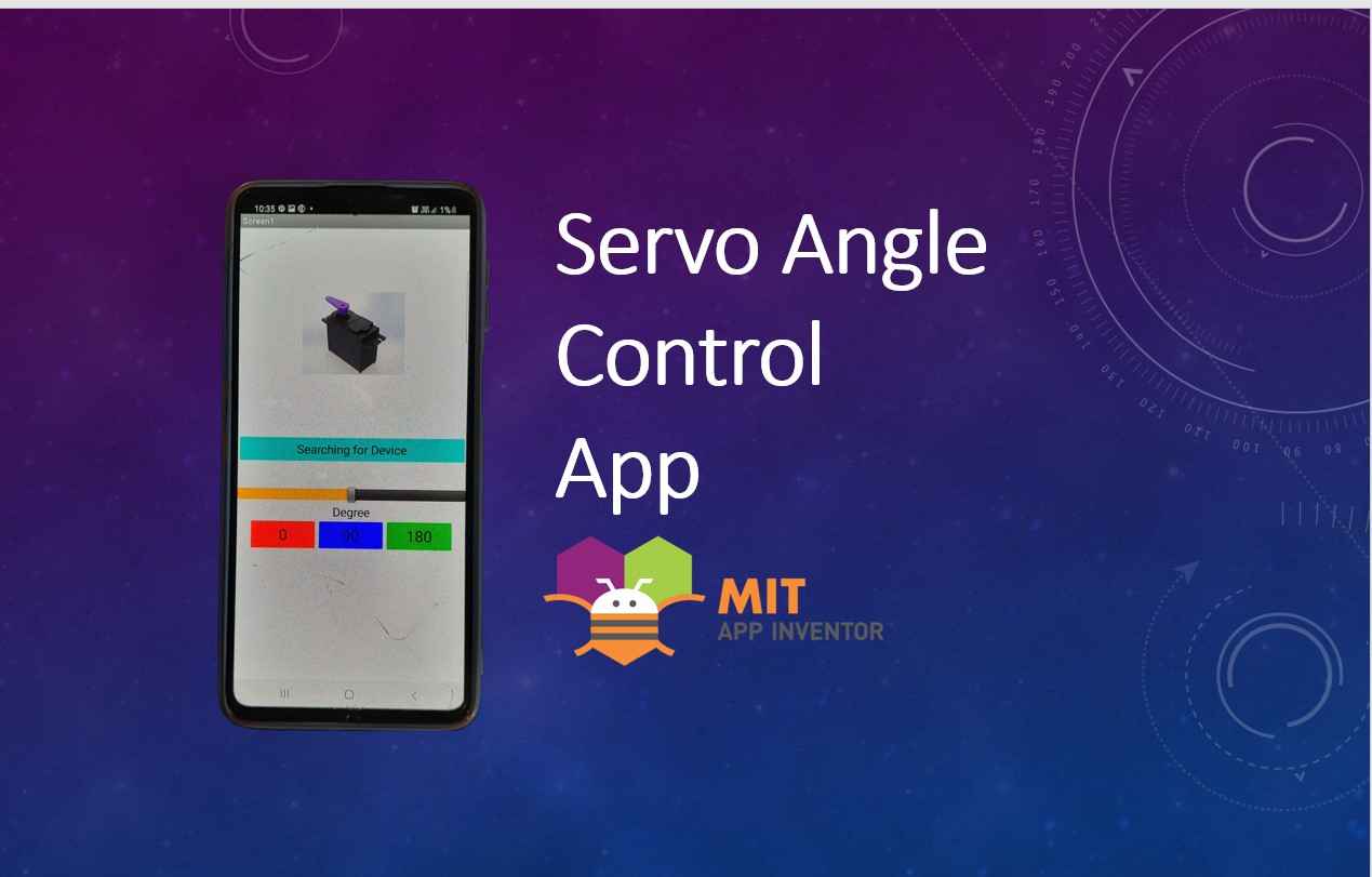
Hero Video:
Here is how I control my servo motor. Using the application I creat.
A small demo of how I use this application to controle my servo motor .