Objective
Design, Build, and Connect wired or wireless node(s) with network or bus addresses
Introduction
What is a network?
A network is a group or a collection of nodes that can communicate with each other to do a particular set of task at a given instance of time.
Eg:- Home Automation
Here every device that you would see at our home is connected to the internet using wifi,ethernet etc.
They talk to a server in this case mostly its the home router ( which acts as a server to get information from outside world) through WiFi or through ethernet if its wired.
The basics is that a sensor or a node would talk to other nodes and the server to perform some set of tasks. In electronics we can this as IOT (Internet Of Things). Another example is Amazon Alexa or Google Assistant.
These are smart devices that can interact with human beings and get information on the fly.
The internet is called as the network of networks because each and every network out there needs to communicate to the outside world and when this happens for several other nodes then onternet is formed.
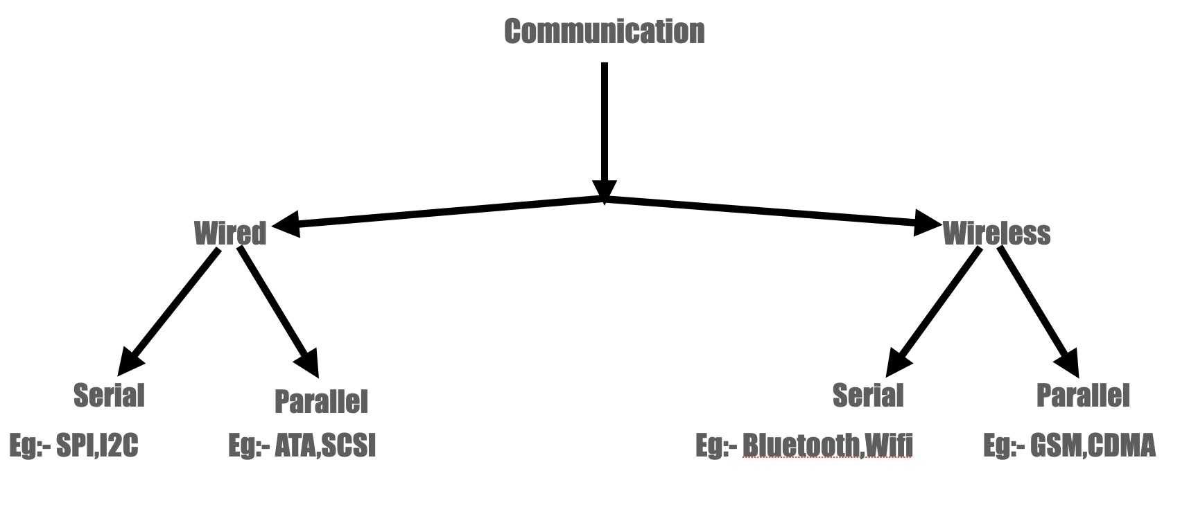
Communication
There two types of communication wired and wireless thses can be further subdivided into various categories.
OSI layers
There are 7 different OSI layers. These are also called reference model. Most of the networking equipment that we use follow OSI layers.
Physical layer
Physical layer is the first layer of the OSI model as the name suggests it is the physical connection of a node to the network.
This can be explained with wired networks with run on ethernet where there is a physical port on the PC there we are using to surf the internet.
The ethernet port that we use to connect to internet is called RJ45 and is capable of handle power line and data line.
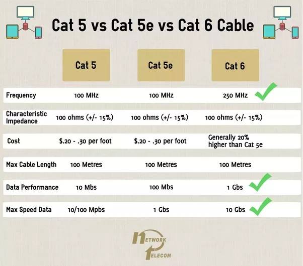
Since its a wired network to link everything physically we use a commonly called LAN cable which in technical terms is is called CAT5,CAT5E or CAT6 cables.
The above mentioned names of cables are its types and below there is an image depicting the differences of the types of cables that we use to connect different devices.
DataLink layer
Datalink Layer is the second layer in the OSI model it is also called the protocol layer. Its further sub-divided into two layers called MAC layer which has the MAC (Media Access Control) address of the device and the LLC (Logic Link Control) Layer. The main purpose of DLL is to divide the data packets into data frames. In summary Datalink Layer handles a process called framing.
The DataLink layer checks errors, network topology and even flow control. This means that the layer will ensure that data are delivered to the proper device on a LAN using hardware addresses and will translate messages from the Network layer into bits for the Physical layer to transmit.
Network layer
Network Layer is responsible for routing of packets it provides the address and location at which a packet has to sent or recieved. IP (Internet Protocol) works on the network layer. Its also known as
Transport layer
Handles the transmission of packets in the network.
Session layer
This layer manages the sessions for the presentation layer. Dialog control between devices also occurs at this layer.
Presentation layer
The Presentation layer presents the data to the application layer its responsible to perform data translation and formatting. This layer also handles compression,decompression and encryption of Data.
Application layer
Application layer is the layer where we have user interaction with the device. User communication happens at this layer with the device. eg:- You internet browser like firefox even if we diconnect ourselves from the internet we would still be able to view a PDF document on a browser like firefox.
This application alone shows the purpose of an application layer. An application link provides an interface to the presentation layer so that the user can interact with the device in a seamless manner. Application layer hosts the actual application that we are working on a device example:- Excel, PDF Viewers etc.
Different Protocols used in communication
There are alot of differet types of communication protocols used in our day to day life.
Some of the common examples are HTTP and TCP/IP
Some other examples of communication protocols are VoIP and VoWifi.
Routing Protocol
TCP is abrreviated as Transmission Control Protocol.
TCP ensure a smooth transmission of data over the network. It works with IP to carry out a seamless delivery of packets to the desitnation that why in the netowrking world we Pronunce both as TCP/IP.
One handles the address and the other handles the security part of the data being transmitted.
TCP header has been shown below.
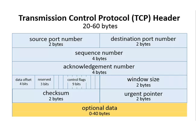 source:- lifewire
Source port address:- This is the port address of the sender who is sending the message its called port address because TCP works on two standard ports which are 65, 535. When any application sends a request to the internet its port address is recorded for faster delivery. Every protocol on computer network has its own dedicated port address.
Desination port address:- This is the port address of the reciever, here a reciever could be a remote server or an edge computer.
Sequence Number:- A sequence number is a counter that keeps track of all the steps that were involved in establishing a TCP connection.
Acknowledgement Number:- Its used to communicate between two computers or devices that they acknowledge the connection. Just like a confirmation between devices.
SYN:- Synchronous bit is a control bit that is used to intiate a TCP connection.
Control bit:- These are bits used to control a three way handshake.
An image of 3 way handshake is shown below.
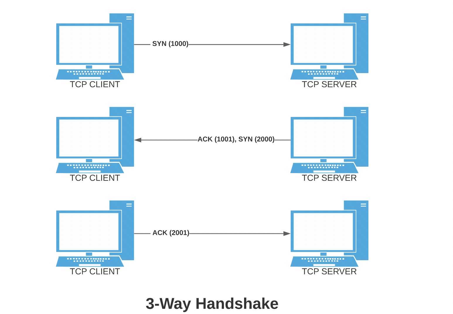 source:- Baeldung
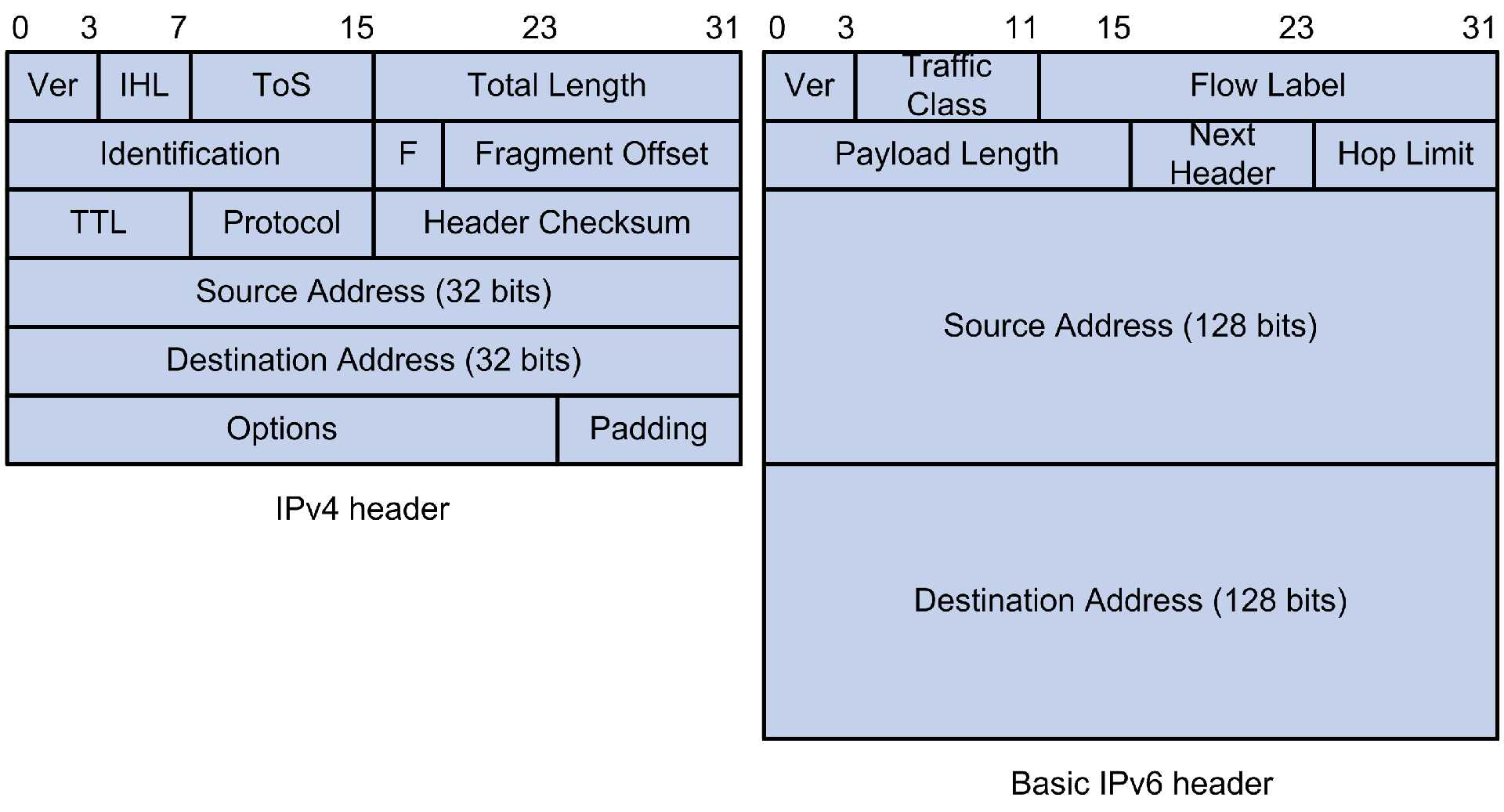
Also abbreviated as Internet Protocol has two versions IPv4 and IPv6. In India IPv4 is still a dominant method to connect to the internet. IPv4 started showing its aged when the number devices that were connected to the internet started to hit a threshold limit.
At max IPv4 can only handle around 3 billion devices this means that there were no enough IP addresses left for new wer devices to connects thats the reason that we have IPv6. IPv6 can handle more than 30 billion addresses thats 10 times more the amount of addresses present to be given to newer devices.
IPv6 can also handle larger amounts data with ease.
An image below shows to comparison between the header packets of IPv4 and IPv6
 source:- IPv4 and IPv6
Project Update
You can see the previous project updates in the documentation of input devices and output devices assignment. In this week I was thinking of networking and sharing the data over thingspeak ( a cloud based IOT platform fir data logging).
On the backend thingspeak works on TCP/IP and UDP but dosen't require som much of processing power. First I have to connect my board to a network for that I use WiFi to connect to the LAN wirelessly then I had to create a channel over thingspeak so that the data could be sent over to be shown over the network as a broadcast not multicast.
You might be thinking that about the terms broadcast and multicast or its difference atleast. A multicast means providing information to a specfic group or only a few number of people the size of the group dosen't matter whether it is you alone as a person or a group of friends and family.
But broadcast on the other hand is to provide information to all of the people around you here also the size of a group dosen't matter but the principle is that information is provided to everyone.
eg:- A News channel broadcasts information. Where as a Social Media apps multicast information in a group.
Finally I can project update is about Data sharing on to a public platform.
Channel Sharing
CSMA/CD
CSMA - Carrier Sensed Multiple Access it is a network protocol that operates in MAC layer the CD in ther terminology means Collision Detection.
It works in such a way that transmission of data has become easier. First it listens to the carrier channel if the channel is free then only the algoritm allows the flow of packets. The packets transmitted through the medium then reaches the reciever.
An example of this is wifi network. A wifi works on 2.4 Ghz band and a 5Ghz band this band is in turn divided into different channels. When packets are to be transmitted to a server from your device that time the radio in your device senses the carrier channel if its free then only it transmits the packets.
There is a probability that multiple devices are communicating with the same server at a given instance of time and are transmitting packets like our device ate that instance Collision Detection comes in as a handy way to detect that transmission of packets.
The image below shows how collision detection works as an algorithm.
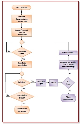
The code for the same can be found here.
Sending Messages to control a fan (IOT application)
After connecting ESP32 to the internet using Wifi it has to perform some task or have an application.
So I came up with a plan to control a fan using simple messages. I ooked around my place for options eventually I found out that
I can use Whatsapp (most popular messaging app in India) as a messaging service to connect the project to th internt.
First I needed access to Whatsapps' APIs for that I used a service called Twilio.
To access Twilio please click here.
Twilio has a whatsapp messaging service that creates whatsapp sandboxes perfect for chatbot applications.
To connect the project to the internet I used another API from ThingESP.
To access ThingESP please click here.
Thingesp project acts as a middle man to the main project board and Twilio and keeps logs.
I won't be showing the setup part of this project as its a redundant process of creating account and project but I will be linking a video that will give you a walkthrough.
After connecting and testing the project I was able to get a result shown in the video below.
A look at the thingesp dashboard
Since I used thingesp to connect my project lets have a look at its dashboard.
Below you can see the dashboard of thingesp. Its a look before connecting our board to the project.
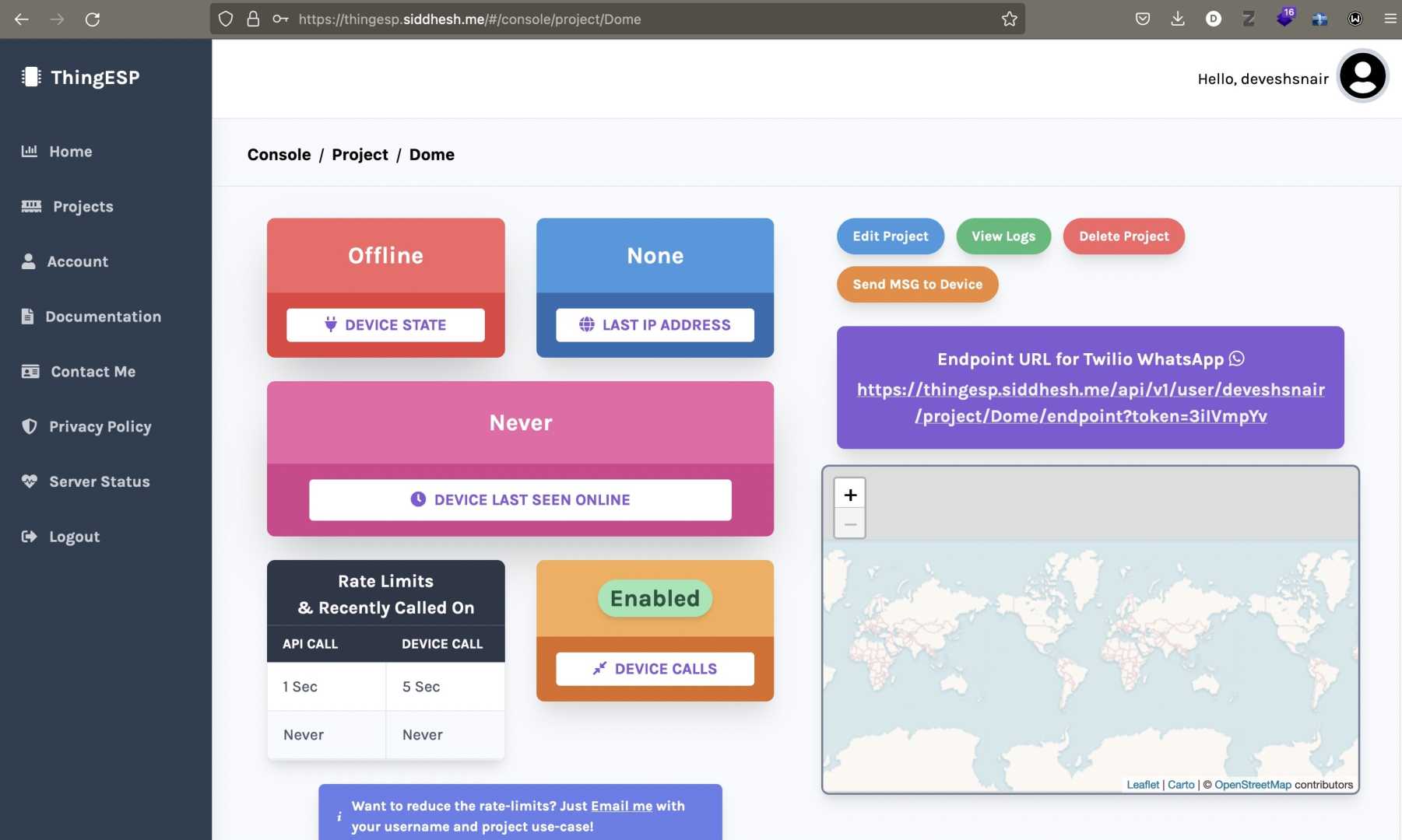
We get a clean interface to look upon. The above image shows that the project is offline.
Another image below shows when the project was online while the video was shot.

The project communicates with the board using the project credentials and over IP.
We can see the Public IP address of our ESP32 in the previous image.
Our ESP32 itself is given project crendential which is ESP321 which is set by the user using this credential we can thingesp verifies that the board is the right one and then communicates over IP.
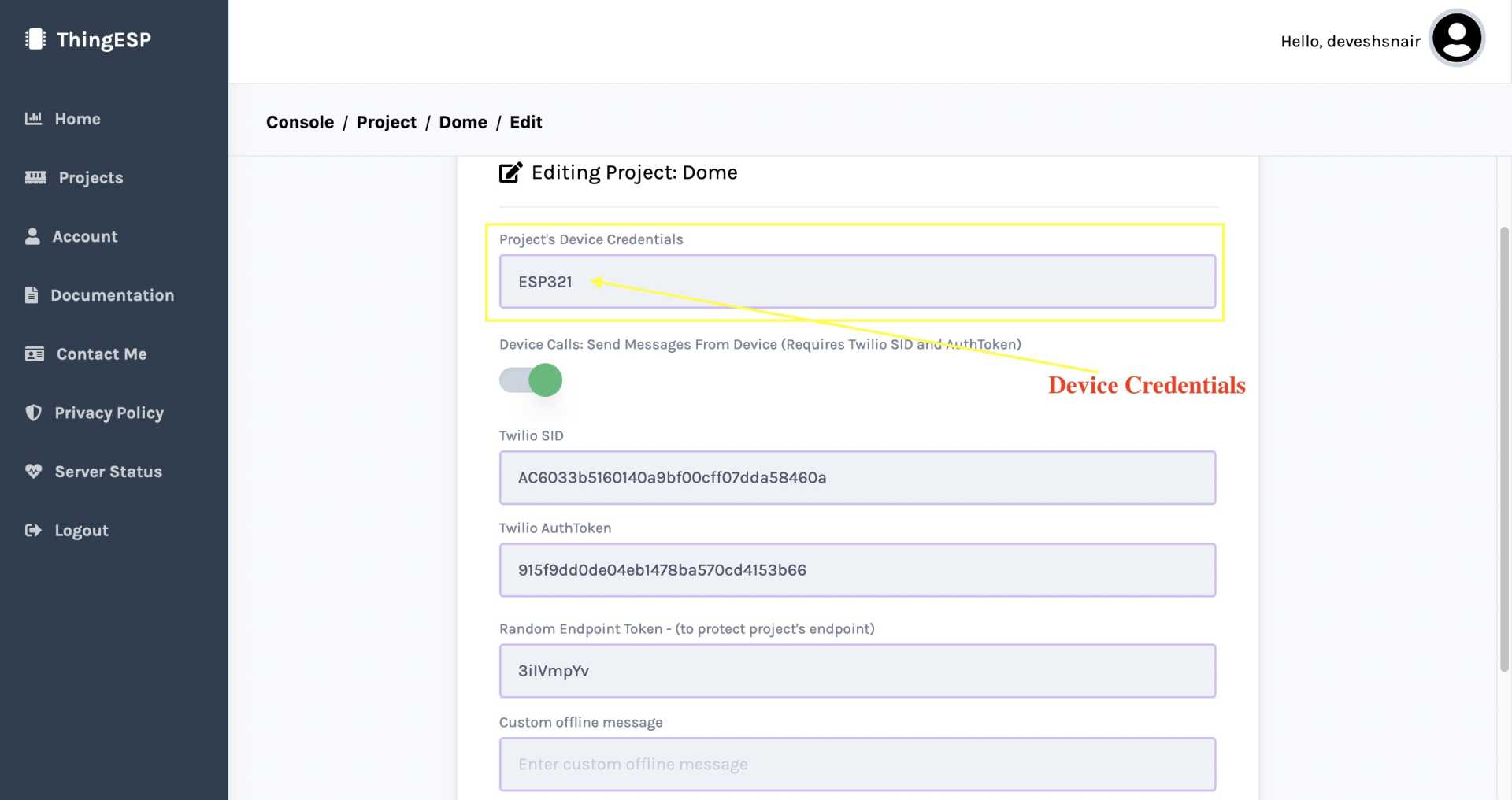 Image showing device credential
Logs
Thingesp keeps logs of the messages or commands sent to the device.
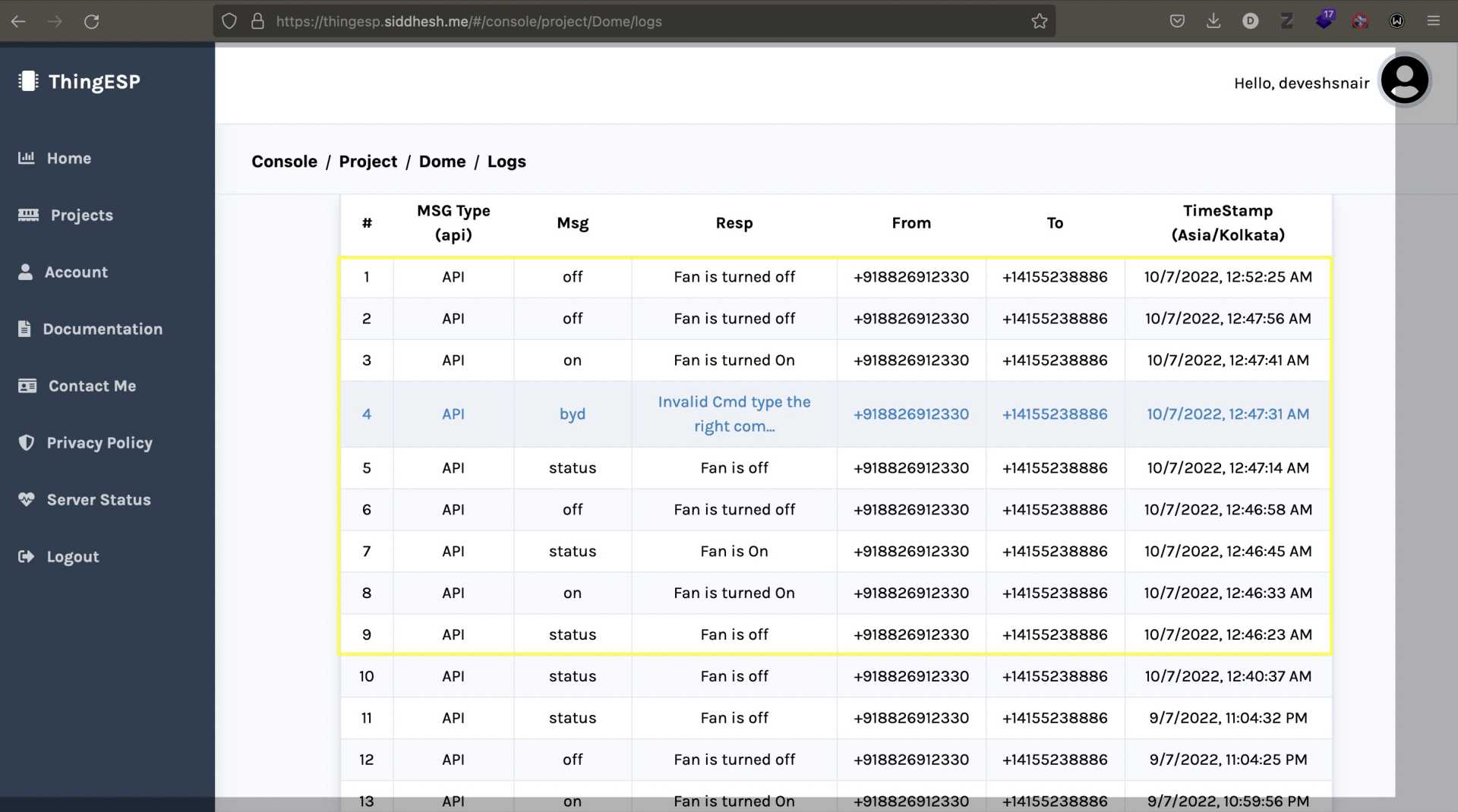
The image above shows the logs of the messages sent over whatsapp during the test in yellow box.
My Experience and something that I learned
This week was quiet descriptive I had to explain myself how things work in the networking world. Secondly figuring out the problem in your project takes half of the time.
The input devices must be readied to log data for further if there is a bottleneck then we should remove them quickly. I learnt one thing I feel its important to document over here that was learning to fail quickly is a skill if you can't do something within a span of 30 mins then we should reshedule that work for another timeslot or a later a date. Its very import to follow this strictly.
Keep yourself in check. There will be alot of issues with the project from the programming side and the technical side also but have to maintain our composure.
Networking one of those areas that need patience sometimes it works and alot of times it breaks if it breaks its might not be your fault but it might be because of a server side issue here I would reccommend you to only upadate project to the latest settings.
Programming
The souce code for this project is done using Arduino C there are alot of bottlenecks in the code also like setting up the input devices, setting the channels for data transfer over the internet etc.
Do remember to debug the program in a joyfull way read the errors properly half them will have a fix in yopur lab itself. Just find time to research your topic or objective over and over again.
Group Assignment
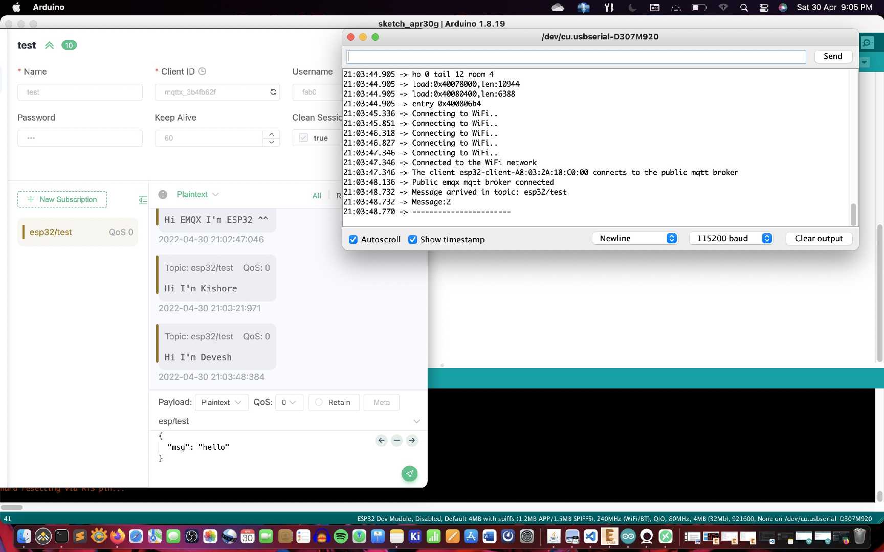
Send message between two projects
In this weeks group assignment we just tried and tested a method to send message between two project.
The projects were based on ESP32 we used Wifi to connect to a lan and had a MQTT broker to perform the exchange of messages. The MQTT software used wasMQTTX.
To make esp32 act as an MQTT client we had to use a library called PubSubClient. This library allows the setup of esp32 as an MQTT client.
Then both the projects are connected to the MQTT broker using the server credentials then made to communicate using the code uploaded on tho ESP32.
A glimpse of this shown below.
Design Files
Source Code fProject connecting over wifi
Messaging source code

Fabspace by Devesh S Nair is licensed under a Creative Commons Attribution-NonCommercial 4.0 International License.