Objective
Add an output device to a microcontroller board you've designed and program it to do something
Introduction
In this week we were given an introduction to output devices. Output devices are those which show data to a user in a readable format eg: For a computer the output devices are listed below.
Monitor
Printer
Speaker etc.
Here we were introduced to quiet different components which are based on real-life applications like:-
LCD display
OLED display
Buzzer
DC Motor
Stepper Motor
Servo Motor
LED
RGB LED
Relay
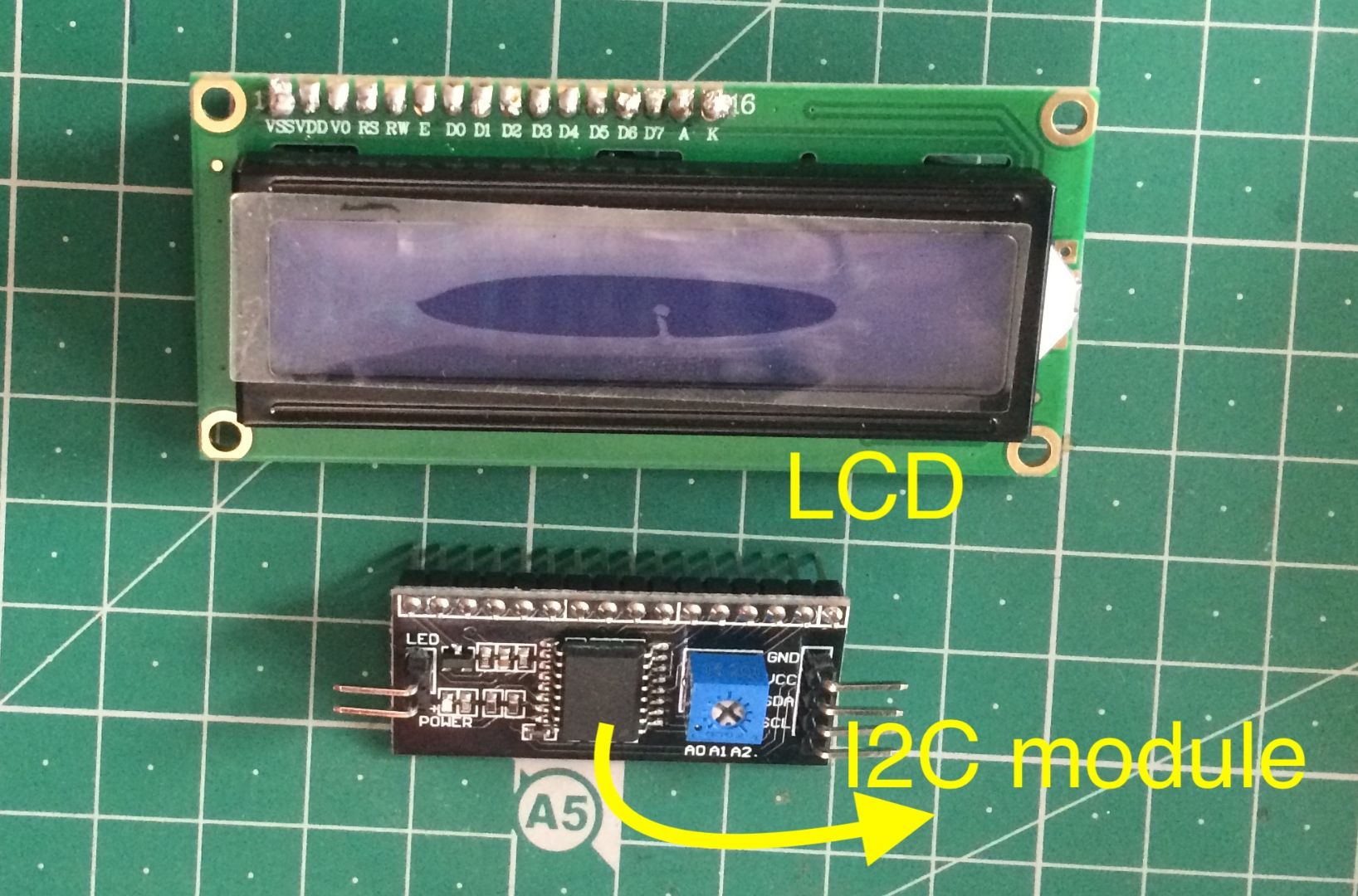
LCD Display
LCD abbreviates to Liquid Crystal Display it contains 16 pins for display. It is often used with an I2C module due to the usage of only 4 pins and offering a serial communication with the microcontroller. It is often called 16x2 LCD display which means that it can show a max of 16 character in 2 rows.
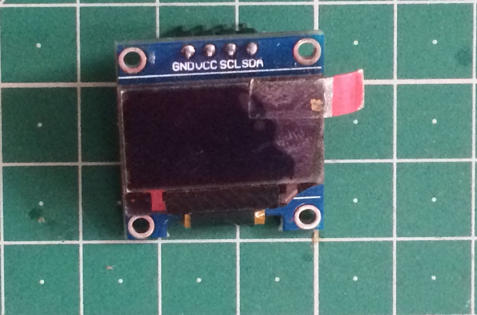
OLED Display
An Oled is slightly better than an LCD since it can show deeper and darker black pixels than an LCD. The power consumption of an oled compared to an LCD is also lower adding more to its efficiency.
It works on the I2C protocol i.e It contains four 4 pins for operation and dosen’t need 5V supply also the operating voltage for the Oled is as low as 3.3V.
Since the manufacturing process is costlier than an ordinary LCD its also becomes the reason for an increased cost.
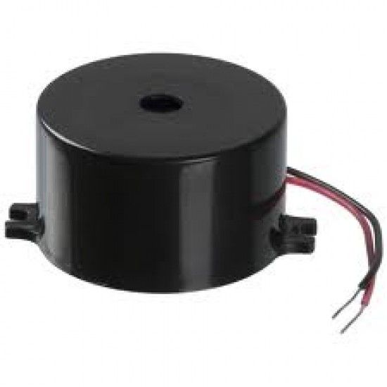
Buzzer
A piezo-electric buzzer is used to generate audio signals or sound its used in various DIY projects and is mostly used like an alarm.
Eg: Burglar Alarm project.
The input voltage range is 5V to 30V
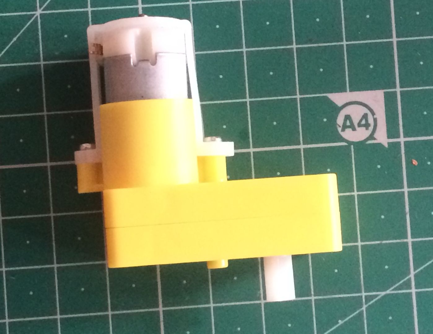
DC Motor
As the name suggests this motor works on DC. There are various types of DC motor that can be differentiated based on the input voltages. These motors are mainly used for high torque applications and perform different from a stepper motors. They are not used for instep applications instead for power.
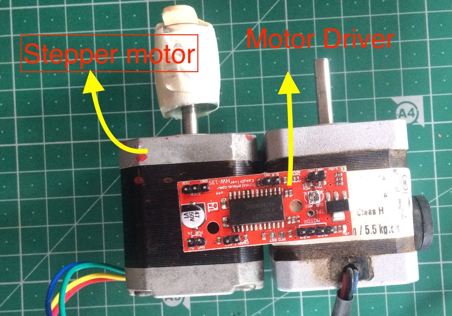
Stepper Motor
Stepper motor are used for calculating steps of rotation accurately. They are majorly used in 3-axis machines and other CNC applications.
Servo Motor
A servo motor is similar to a stepper motor there are two components in a servo motor they are:-
DC motor and
A set of gears (made up of plastic and metal)
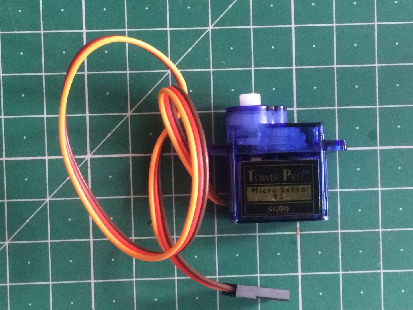
In this picture we have showed a SG90 micro servo motor which uses plastic gears there is a bigger brother of this component by the name MG90 which uses metal gear. The metal geared motor is used for long term applications.
LED
Light Emitting Diode is the most common output device used in embedded programming
RGB LED
RGB in the name stands for Red Green Blue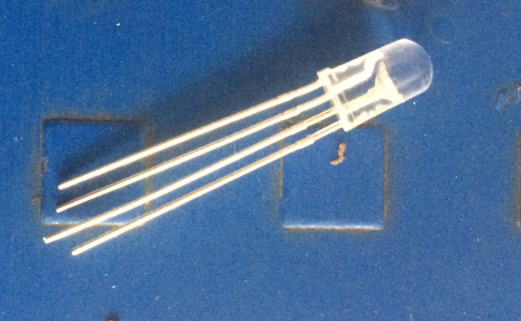
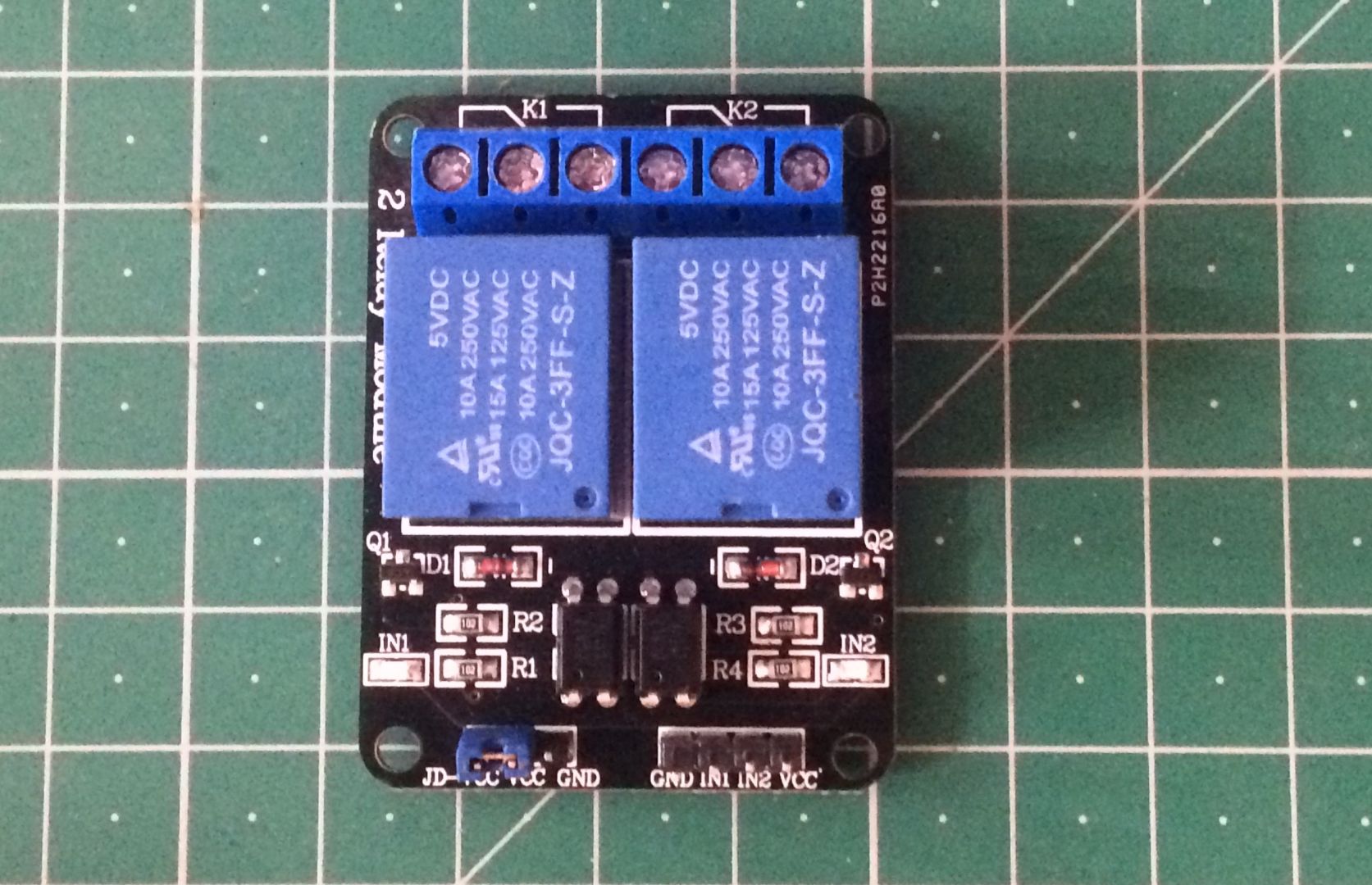
Relay
A relay is switching circuit which can be controlled by digital pulses but can switch or operate an AC appliance.
For the project I'm using a single channel relay. A relay is also called an N-channel relay where N mean the no of relays present on a board.
There are multiple channel relay available in the market. I'm using a 1-channel relay for the project. The picture above shows a 2-channel relay.
The relay works in 2 configurations NC- Normally Closed and NO- Normally Open configurations.
NC - Means current only flows when the pin is give a high signal.
NO - Means current only flows when the pin is given a low signal.
My Experiences and problems
I tried to create my final project board and in the process lost my mind the main thing untill this week is not to loose hope and realign yourself to the project plan.
Reinvent yourself but not the wheel would be the advice I would give.
Eventually I readied my project board. Dealing with output devices isn't a problem for the most part in my project I have a 1-channel relay and an OLED display. A relay is easier to test than an OLED. There are issues with each and every component that I tested. Im documenting only two as a part o my project.
The main problem that we face during the testing phase is that we proper pin programming isn't followed some of the issues are common and have pretty easy fixes also.
I used hope on to stackover flow or mattermost to find and research about some of the errors.
Weekly assignment
Design a board for otput devices
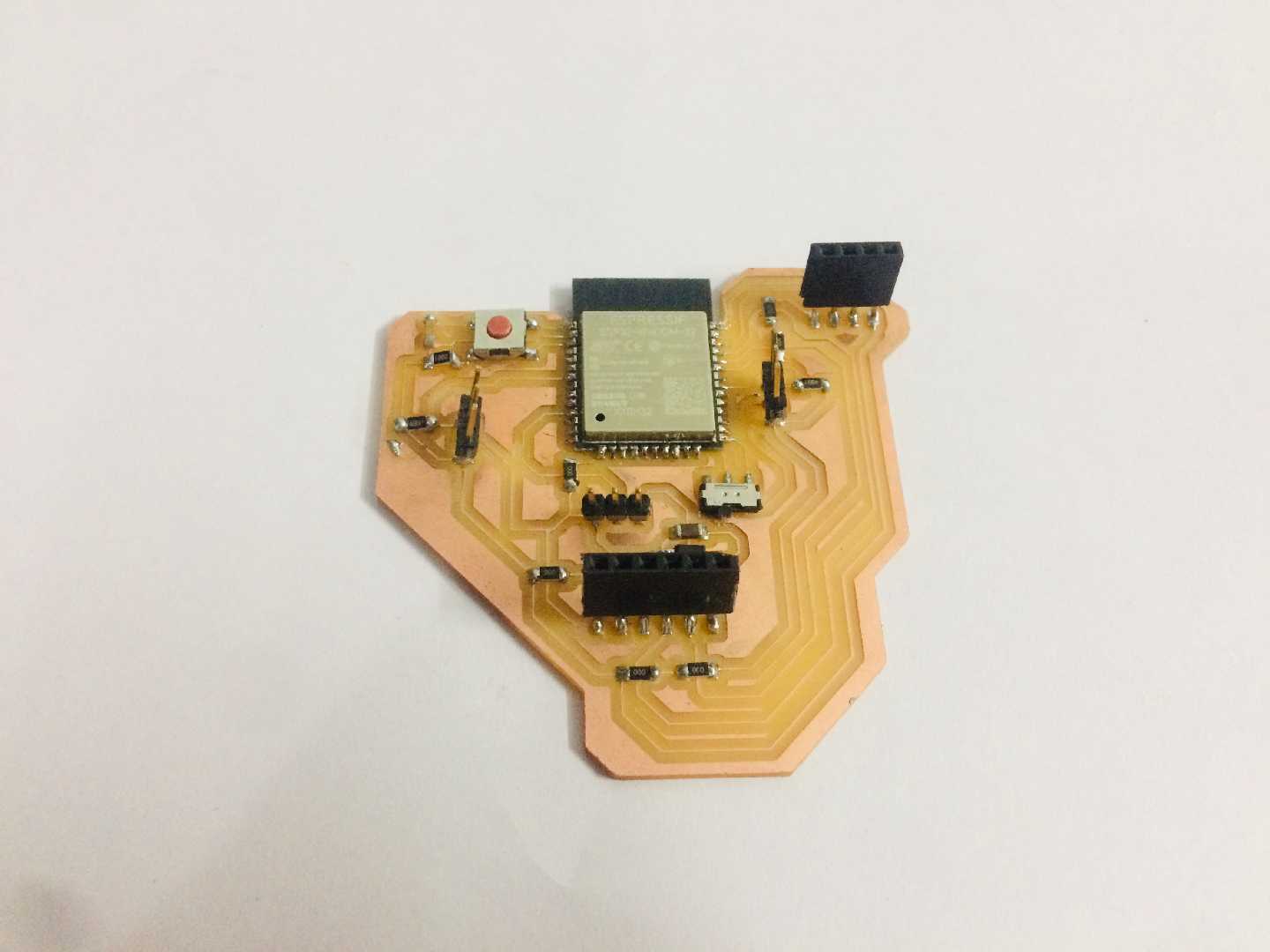
For this weeks assignment I’m designing a board with the chosen microcontroller i.e ESP32 which belongs to the Xtensa family. For the output devices I’m also interfacing an OLED Display and a Relay. This is because my project on the output side requires a display interface and an AC fan.
Project Board Design
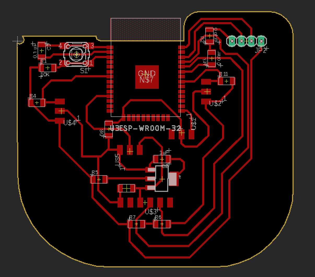
The image shown below depicts the project board that I created for the airflow system. Please remember by this point my whole week went in designing and testing the output devices. Some of the tasks were leftout.
The picture of milling the board will be linked here.
What I learned from interfacing output deives to the board
Output devices are of different types and purposes we have to choose them according the purpose that we need.
Output devices work on different power levels some work on 5V while others works on 3.3V in my case teh OLED that I'm using works on 3.3V.
Check if the ouptut device that you are working run on a specific protocol and research on it before hand. In my case I'm using a 0.96" OLED display that works on I2C protocol and had to reserve separete pins for those in the design it self.
Programming using Arduino C and Embedded C both works.
Wiring an output deivce properly eliminates 90% of the errors in the system. Yes proper wiring of your output device gives a greater chance of success while testing. While programming ensure that the Pin activated is the same pin that the device is connected.
Rest the device once or twice for expecting desired outputs. Resetting solves major errors that occur in the system.
An update on the project
There was a quick change made to the board design which simplified the application of Ouptput Devices used.
OLED was used during the boards testing the testing video is provided below.
The main reason for this change was that the previous project board failed to serve its purpose due to bad connections.
The power pins of the oled were also changed in the new design.
Testing video
Below you will find OLED being tested using the ESP32 board that I created
Group Assignment
Measure the power consumption of an output device
For the group assignment we tried and test and checked the voltage and current of some of the output devices eventually calclating the power consumption. First we used a LED module and with a DC Motor connected to LMD319 motor driver. For further information access the group assignment.
Click the link to visit the group assignment page.
Design files
original design file and source code for the OLED testing are linked here

Fabspace by Devesh S Nair is licensed under a Creative Commons Attribution-NonCommercial 4.0 International License.