Objective
Add an Input device to a microcontroller board you've designed and program it to do something
Introduction
Input devices/sensors are such components that can sense an external change in the environment and give back a machine readable input to the controller or the processor. It could be in an analog or a digital.
The output provided by the sensor decides the type of input sensor it is.
Eg:- If an input sensor gives a analog output then it could be called an analog sensor if it gives digital values then it is called a digital sensor.
There are a wide range of input sensor that can be found on the market today. Just like saying there is an app for that.
eg:- A temperature sensor , audio sensor, motion detection sensor, an IR sensor etc.
These sensors work on some simple principles and are easy to fabricate with tha availabilty of the right tools.
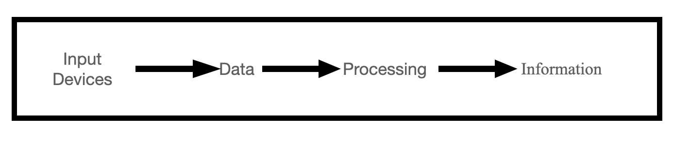
Last I would like to say that Input sensors are used the get usefull data after which it is converted into usefull information for humans.
Data to informatation
The literary meaning of data is given below.
The quantities, characters, or symbols on which operations are performed by a computer, which may be stored and transmitted in the form of electrical signals and recorded on magnetic, optical, or mechanical recording media.
source:- Oxford Languages
Datum is a piece of fact or wordings or parameters that dosen’t mean anything usefull this data has to be further processed to get information and inferences.
In the field of biomedical image processing engineers deal with alot of data particular in the number of thousands that it dosen't make any sense but when a doctor is shown with some of thses images he/she may be able to come to a conclusion about a particular subject that are observing.
eg:- Xray and MRI scan images etc.
The image below shows the coversion of data into information.
DS18B20 temperature sensor
For this week I would like to focus a bit towards the final project that I want to build over here at Vigyan Ashram. Its the airflow system of a smart dome dryer.
The dryer is used to dry some vegetables and a variety of chilles also. Currently for testing purposes we are using saw dust as a substrate but eventually the purpose is to dry chilles and some variety of spices.
To measure the temperature of the dryer I have come up with the DS18B20 Temperature-humidity sensor by Dallas Semiconductors.
This thing works on 1-Wire bus communication which could make it easier to wire multiple of these and called then using different addressess. The sensor has a operating temperature of -55oC to 125oC
The sensor connects to the VCC,GND and the Data pin of your microcontroller and has a resolution of 9-bits to 12-bits.
An image of the sensor is shown below.
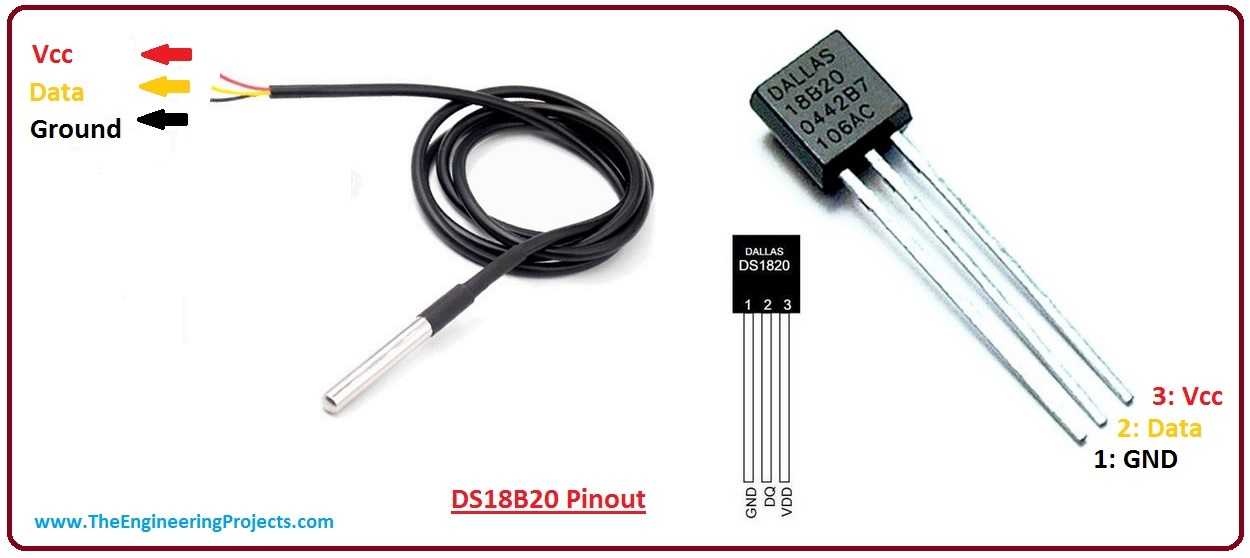 source:- The engineering projects
Over here I'm leaving the download link to the datasheet of the sensor for reference.
The working principle of DS18B20
By this point we all know that DS18B20 is a temperature sensor developed by Dallas Semiconductors. The working principle of these sensors are based on crystal oscillators.
There are High temperature and Low temperature crystal oscillator present in DS18B20 that oscillate on specific frequencies according to the external change in temperature.
Due to some reasons I'm quoating the exact definition of its working principle from the source "The oscillation frequency of the low temperature coefficient crystal oscillator is little affected by temperature. A pulse signal for generating a fixed frequency is supplied to the subtraction counter. The high temperature coefficient crystal oscillator changes its oscillation frequency with temperature, and the generated signal is used as the pulse input of the subtraction counter. When the counting gate is open, the DS18B20 counts the clock pulses generated by the low temperature coefficient oscillator to complete the temperature measurement."
source:- ntc sensors
My Experiences
This week was a bit jam packed for me trying out output devices wasn't an issue instead designing and milling my project board was a big deal.
Since I'm using ESP WROOM 32 Chip I didn't realise that it would be this hard to solder the chip. Other than this I advice all the readers to double check the board the you are going to design and verify the designs with your partners if possible.
During this week experience matters. Alot of troubleshooting was done and it was not easy. Duely remember that troubleshooting an ESP32 is not easy and get all the help that you can. Talk to people who have worked on esp32 before they might be able to help you out.
Make sure that you have your an FTDI programmer at your if not make one for yourself. It very import for esp32 projects.
Weekly assignment
Design a board for output devices (The project Board)
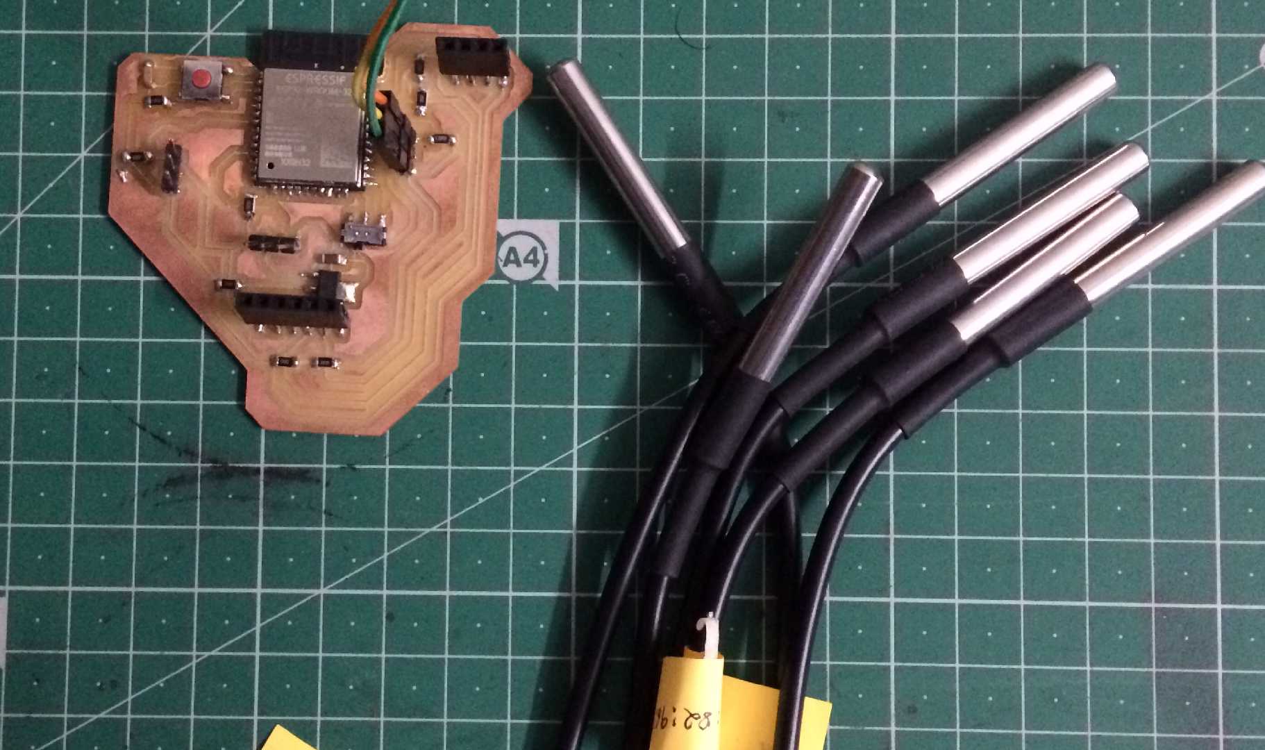
After the output devices week I had designed a board that was to be used in my final project, I decided to mill and get the board into shape. As mentioned in previous assignments my project was based on a smart dome dryer. For this project DS18b20 input sensors collect the temperature data and turn that into usefull information.
A view a the PCB after milling.
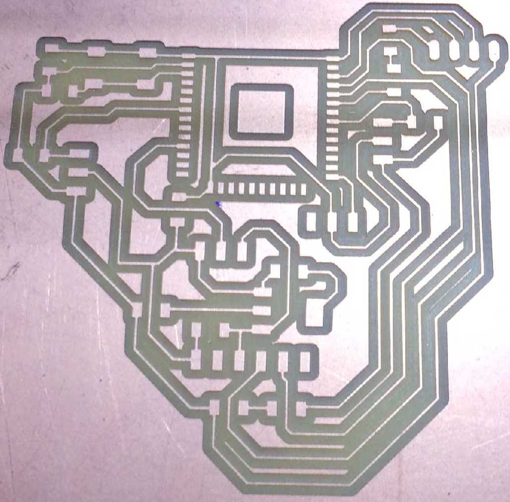
The Original design file for the board is given below in the Design files section.
Programming Esp32
Programming ESP32 isn't a tough job but debugging is I tried my level best to debug the board and last found out errors in design.
I used Arduino IDE to program the board for programming the board the slide switch shoud be set to low i.e:- IO2 pin should be low first.
Then we have to upload the code while uploading process goes on slide the switch IO2 to high this enables programming mode after which press the rest button the code should start to upload.
If everything goesaccording to plan the program will be uploaded or else we might encounter errors like "header packet not found" or "Timeout error". To debug these issues check your design again. The IO2 pin isn't put to ground or might be in a floating state. Make sure your girounds are properly connected. Refer to esp32 board design done by Niel once again.
Arduino IDE
Open Arduino IDE
Connect ESP32 to the PC (in my case mac) using a FTDI programmer
Then goto tools and check for the paramenter that are port,upload speed,cpu frequency and the board.
Write some program that you want upload to esp32.
Click Upload to complie and Upload the code to ESP32.
Set the board to programming mode and press the reset button.
And Vola if there are no errors then be happy you have done it hats off. The program has been uploaded.
Below shows the error that I obtained during uploading the code.
esptool.py v3.0-dev
Serial port /dev/cu.usbserial-0001
Connecting........_____....._
Chip is ESP32-D0WDQ6 (revision 1)
Features: WiFi, BT, Dual Core, 240MHz, VRef calibration in efuse, Coding Scheme None
Crystal is 40MHz
MAC: a8:03:2a:18:c5:4c
Uploading stub...
Running stub...
Stub running...
Configuring flash size...
Warning: Could not auto-detect Flash size (FlashID=0xffffff, SizeID=0xff), defaulting to 4MB
Compressed 8192 bytes to 47...
A fatal error occurred: Timed out waiting for packet content
A fatal error occurred: Timed out waiting for packet content
The error shown above was solved when I interchanged the connections with the RX and TX Pin on the FTDI programmer.
Problems and Solutions
Initially I felt some hiccups using the DS18B20 sensors most of the issues with sensor occurs with connections. As we know that DS sensor has three connections to the board they are:-
1.VCC
2.GND and
3.DATA
If the connection of data and vcc is interchanged then we might experience a bootloop on the ESP32 the solution to this is unplug the DS sensor check the connection and connect to the right pins.
Secondly loose connection issues a breakout board for the sensor is better option it lets your aparatus look a bit cleaner. In future I'm designing another PCB for the sensor I'm fed up with the wiring mess.
Result
The image shown below shows the result of a single DS18B20 connected to the project board.
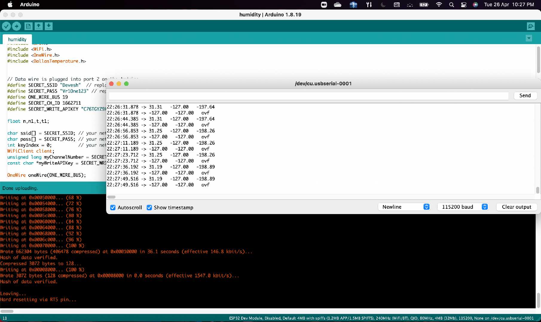 Single sensors temperature readings in Celsius.
Here is a video with esp32 connected to 6 DS18b20 used for testing
Group Assignment
For the group assignment we had to take an input sensor and check the its waveform when its connected to an hello world board.
We used our Digital Signal Oscilloscope to view the input waveform that was given out by the IR sensor.
The components we used were a hello world board, an IR sensor module, some jumppers and a multimeter.
Design files
I'm leaving the source code for download here.

Fabspace by Devesh S Nair is licensed under a Creative Commons Attribution-NonCommercial 4.0 International License.