6. 3D Scanning and printing
3D Scanning
3D Laser Scanning is a non-contact, non-destructive technology that digitally captures the shape of physical objects using a line of laser light. 3D laser scanners create “point clouds” of data from the surface of an object. In other words, 3D laser scanning is a way to capture a physical object’s exact size and shape into the computer world as a digital 3-dimensional representation.
3D Printing
3D printing or additive manufacturing is a process of making three dimensional solid objects from a digital file. The creation of a 3D printed object is achieved using additive processes. In an additive process an object is created by laying down successive layers of material until the object is created. Each of these layers can be seen as a thinly sliced cross-section of the object. 3D printing is the opposite of subtractive manufacturing which is cutting out / hollowing out a piece of metal or plastic with for instance a milling machine.
Learning outcomes
-
Identify the advantages and limitations of 3D printing
-
Apply design methods and production processes to show your understanding of 3D printing.
-
Demonstrate how scanning technology can be used to digitize object(s)
Like the previous weeks , student are expected to complete two (2) categories of weekly assignment.
-
Group assignment:
-
Test the design rules for your 3D printer(s)
-
Document your work and explain what are the limits of your printer(s) (in a group or individually)
-
Document your work to the group work page and reflect on your individual page what you learned
-
-
Individual assignment:
-
Design and 3D print an object (small, few cm3, limited by printer time) that could not be easily made subtractively
-
3D scan an object, try to prepare it for printing (and optionally print it)
-
At the NIHERST Fablab we had access to two (2) 3D Printers and one (1) 3D scanner:
3D printers
MakerBot Replicator:
-
Type: Fused Depositon Modeling (FDM)
-
Nozzle Diameter: 0.4mm
-
Layer Thickness: 0.05mm -> 0.3mm
-
Filament Diameter: 1.75mm
-
Materials: PLA
-
Temperature: PLA-> 230
-
Slicer: Makerbot Print
-
Build volume: 11.6 X 7.6 X 6.5 in
-
Extruder Quantity: 1

Flashforge Creator Pro:
-
Type: Fused Depositon Modeling (FDM)
-
Nozzle Diameter: 0.4mm
-
Layer Thickness: 0.1mm - 0.4mm
-
Filament Diameter: 1.75mm
-
Materials: PLA, TPU95A, ABS, PETG
-
Temperature: 240 ℃
-
Slicer: FlashPrint and ReplicatorG
-
Build volume: 227 x 148 x 150 mm
-
Extruder Quantity: 2

3D Scanner
Nextengine 3D scanner;
-
ScanStudio: Software to Scan, Align, Polish, and Fuse 3D Models. High performance 3D viewer.
-
Standalone Use: ScanStudio works outside SolidWorks for creation of standard format scan output files.
-
Format Options : Scans can be output as STL, OBJ, VRML, XYZ, and PLY files.
-
File Size : 20MB for typical models, based on 10 facet scans.
-
Modeling Tools: Assemble views into a model conveniently with built-in Smart Alignment
-
Minimum System: Quad-core, 16GB RAM, Fast GPU, Windows 7, 8, & 10 (64-bit), 40GB Drive
-
Size :Compact 8.8” x 3.6” (letter size) desktop footprint. 10.9” high. Approximately 7 lbs.

Group Assignment
For our Group assignment we had to test the design rules for our 3D printer, document our work & explain what are the limits of our printer .
The Group Assignment page is as follows Link
Group Members:
-
Nervene Bhagwandass
-
Christopher Proute
-
Terrence Carew
-
James Khan
-
Marvin Holloway
-
Ravi Baldeo
Individual Assignment
My Individual assignment I had to Design and 3D print an object that cannot be easily created by subtractive manufacturing process and 3D scan an object and prpare it for printing.
For this exercise, I knew exactly what I wanted. I’ve always been a huge Star Wars fan as I said before!
So naturally I design the Death Star!

Designing a 3D Object
Began by designing the stand for the Death Star using two (2) cylinders 30 mm and 10 mm diameter .
Solid>create>cylinder

I then created a sphere 40mm diameter and edit the stand using a torus
-
Solid>create>sphere
-
Solid>create>torus
Then move sphere into position using the align tool
- Solid>modify>align


Then I created the main weapon by right clicking the object and using the hole tool.

I then created the surface circumference indentations using a series of torus of varying diameters and thickness. Positioning them and subtracting (cut) them from the sphere using the combine tool in modify.


Note: When completed the design was exported as a .stl file
3D Printing an object
Open the STL file by selecting the “File>Open…” menu option

I was happy with how the object looks right now, and skip ahead to “Generate the toolpath” ,but you Manipulating the object using:
-
View
-
Move
-
Rotate
-
Mirror
-
Scale
These tabs are located in the right lower side of the screen

-
Object Infill dictates the density of your print. 100% infill will make your object completely solid, while 0% will make it hollow.
-
Layer Height is exactly what it sounds like: it determines how flat each layer of your print is going to be. The default is around .3 mm, but you can experiment with layer heights as low as .1 mm if you’re looking for finer detail.
-
Number of shells refers to the outer structure — the thickness of the perimeter your bot prints on each layer before it starts on the infill.
-
Feedrate is the speed at which your bot moves while extruding plastic,
-
Travel Feedrate is how fast it moves when it’s not extruding plastic
-
Print temperature adjusts the nozzle temperature
The defaults are a good place to start, but you might want to experiment with setting them a little bit lower.
click Generate Gcode >Click ok

Begins generating the gcode

After which the object will start to print


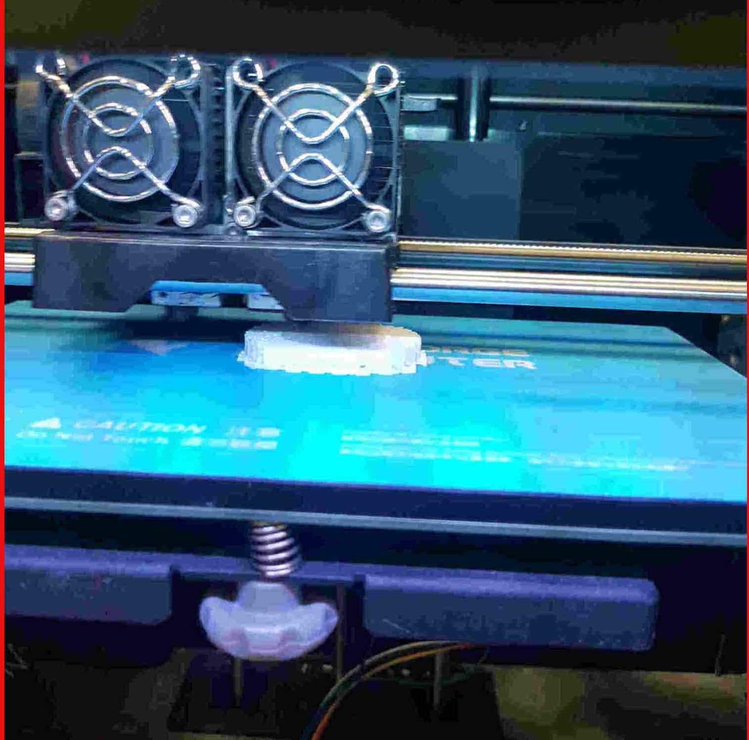
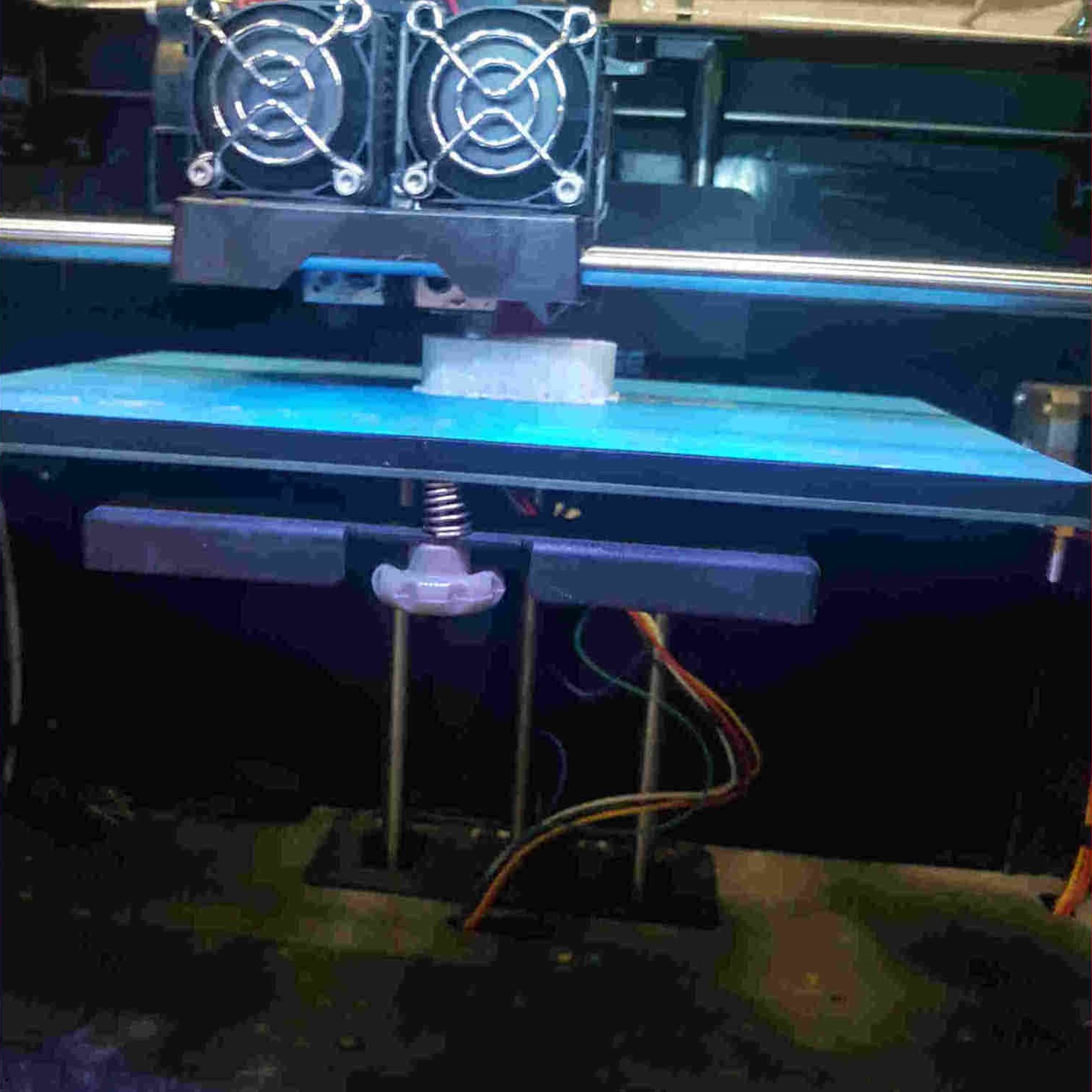
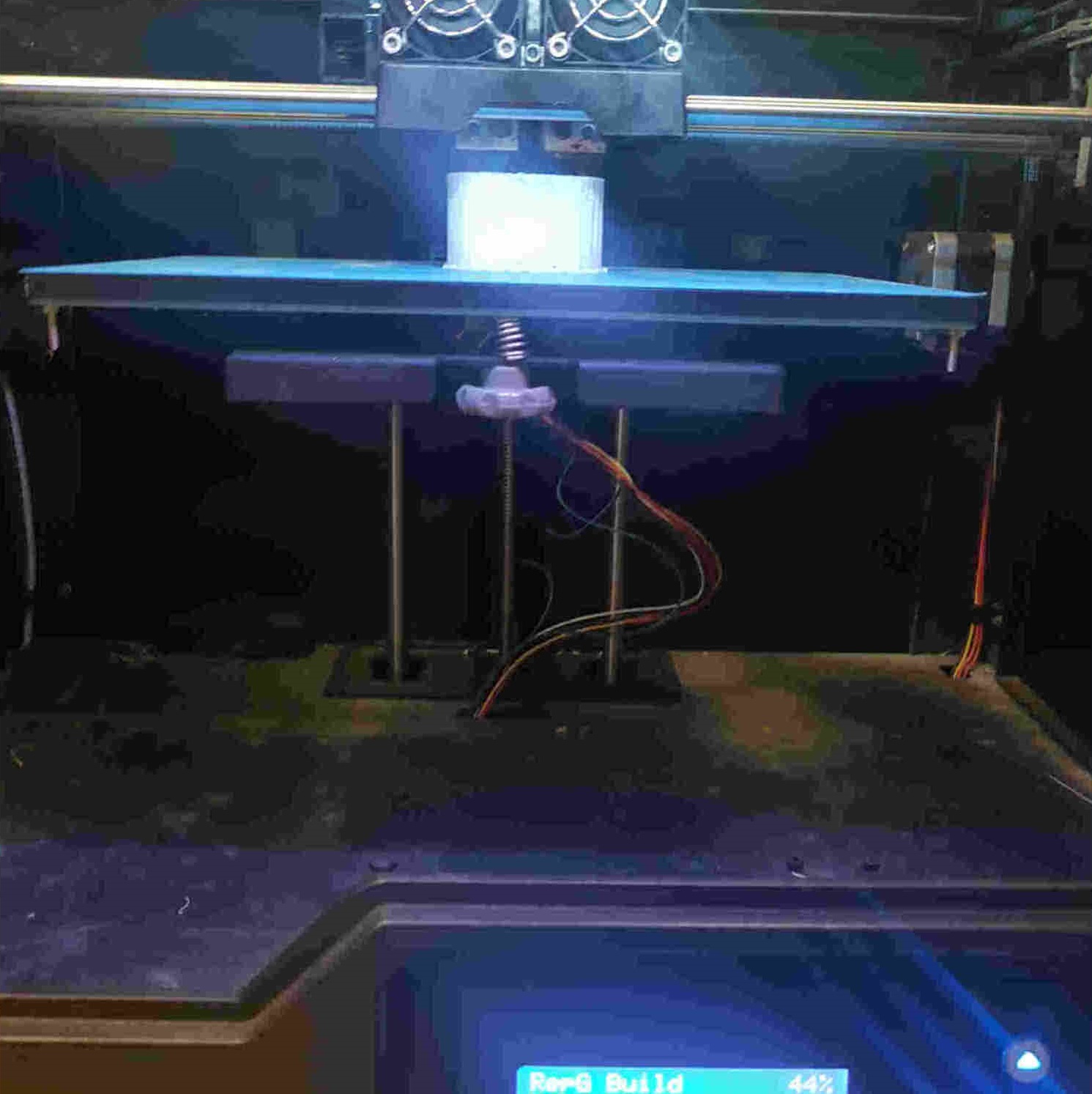
3D Printing Process
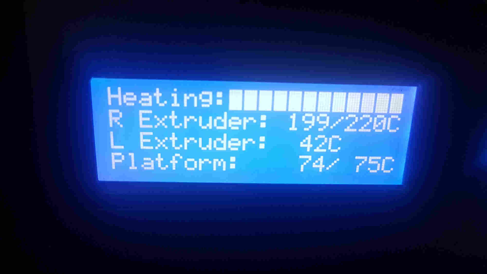
0%
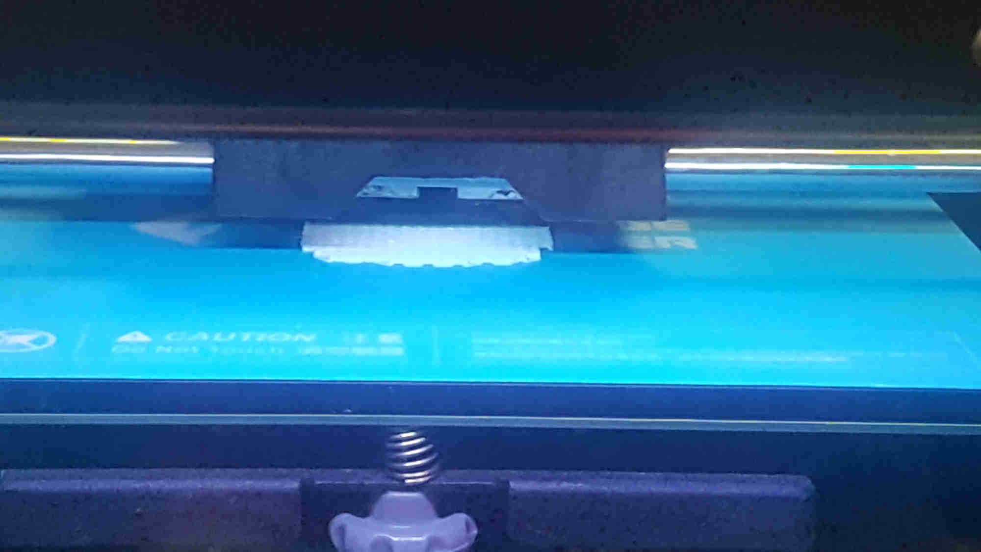
18%
27%
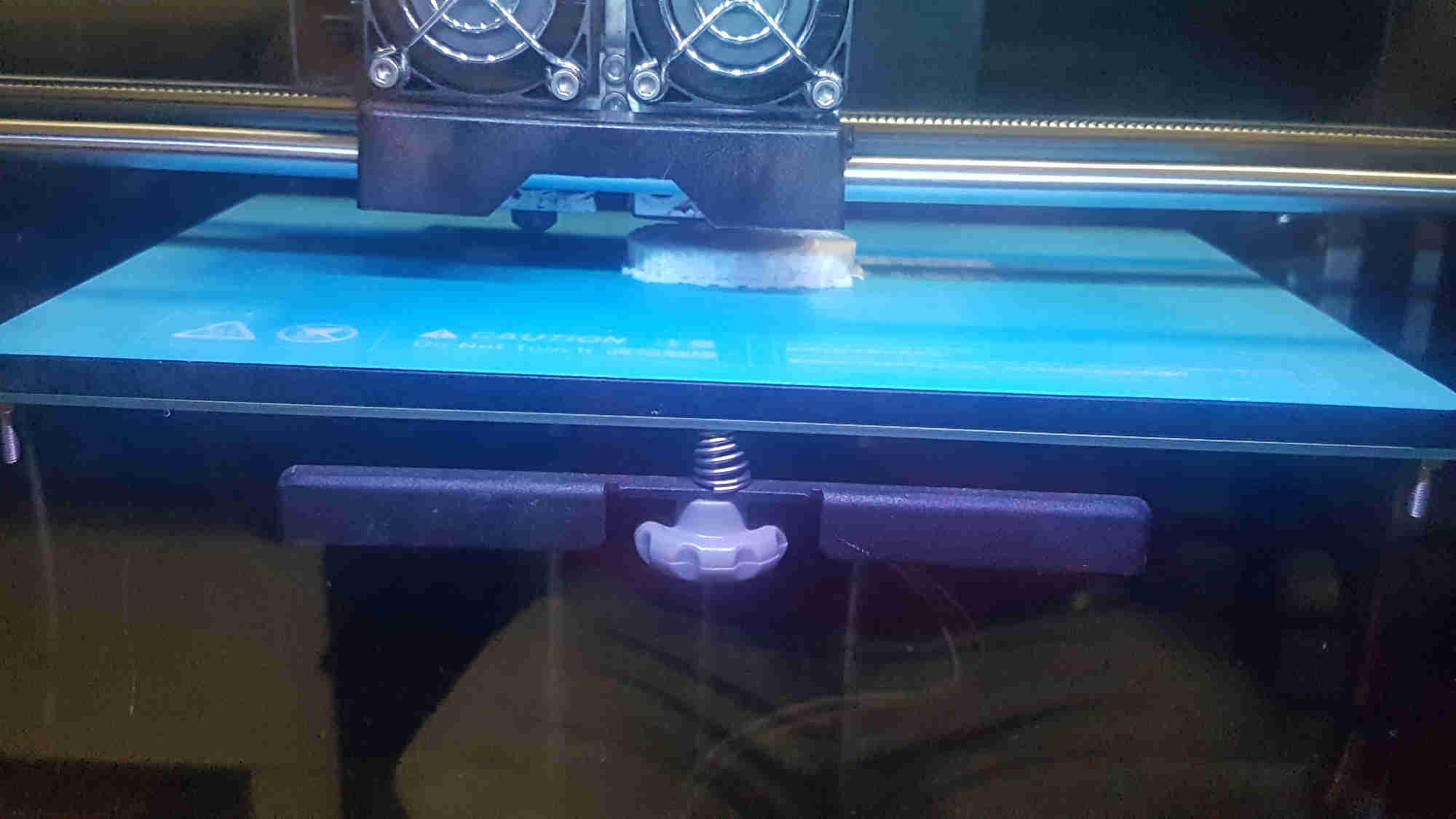
35%
48%
53%
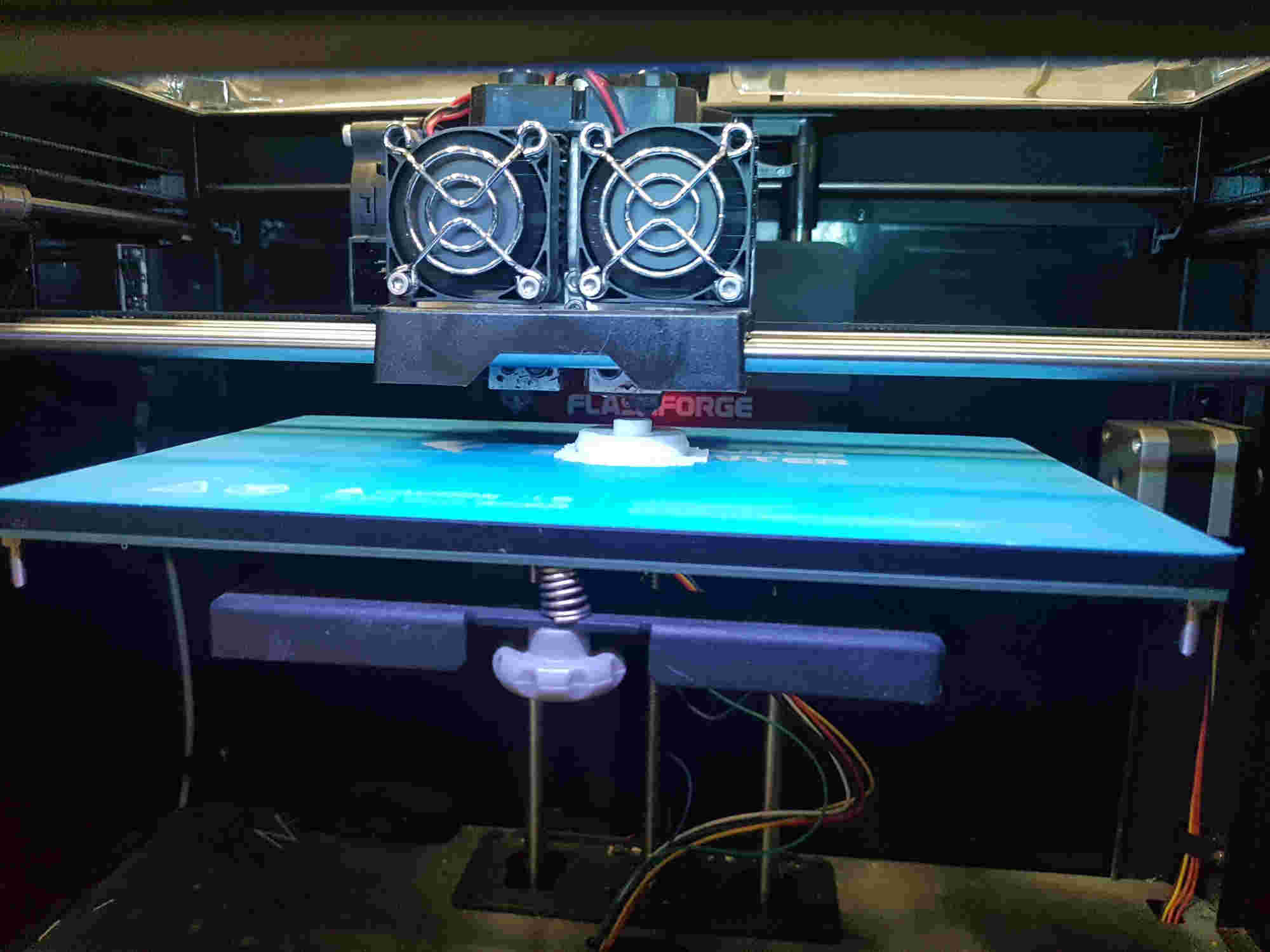
64%
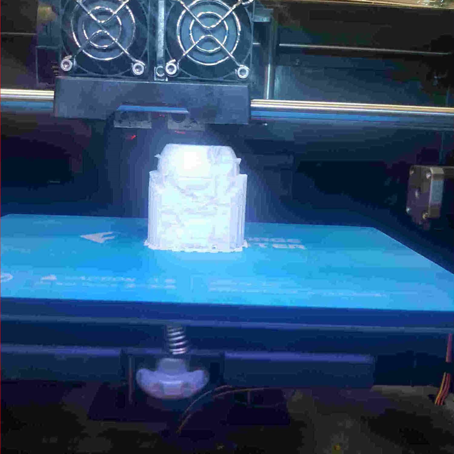
83%
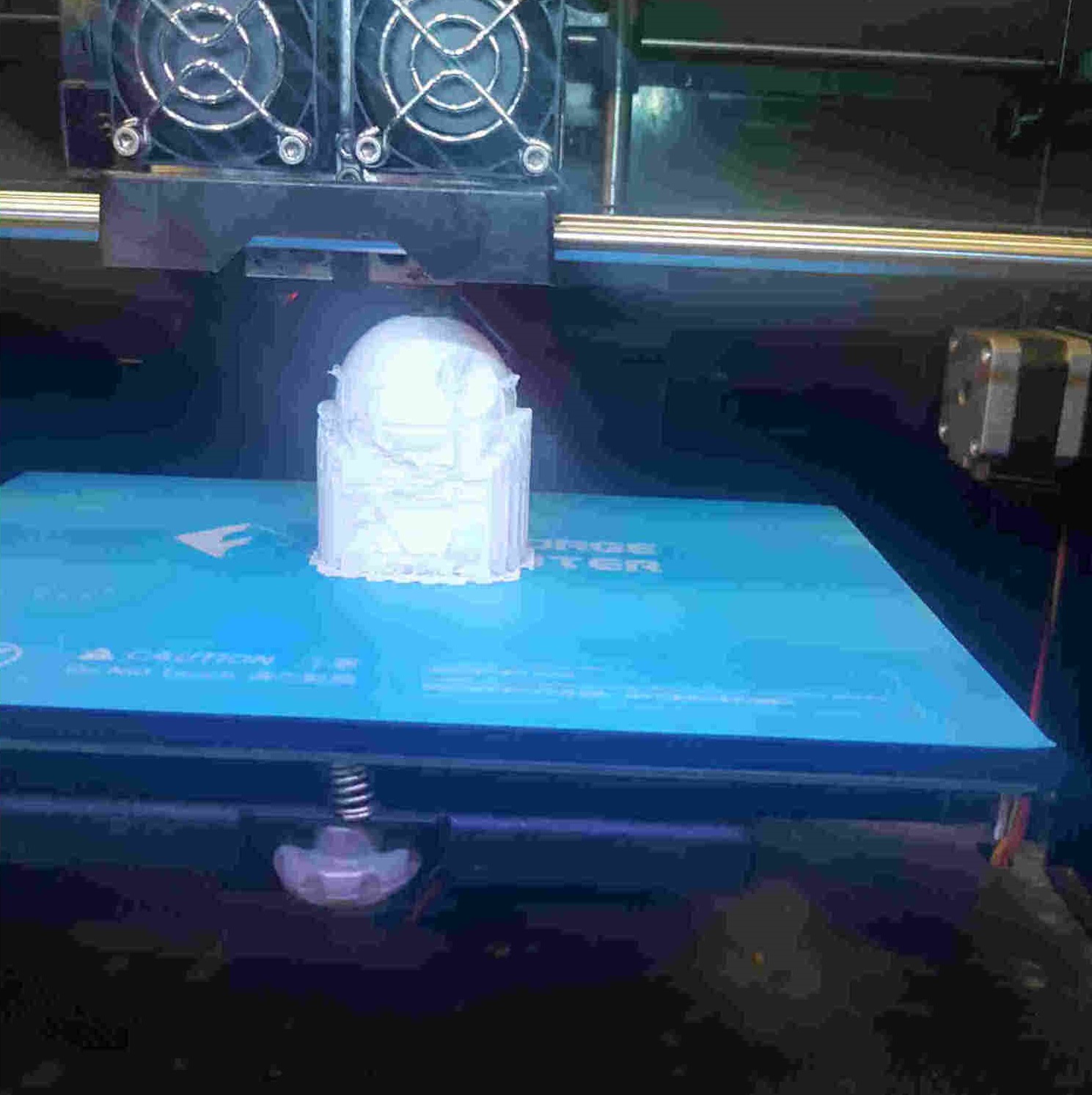
97%

A bit ruff on the outside due to support material

Try experimenting with different color (transparent red and black) but again had an issue with support material. Black had a filament jam issue
 Next try would be without support
3D Scanning an object.
Although I had access to 3D scanner the group have difficulties accessing the account so I attempted the scanning lesson using photogrammetry.
Photogrammetry
Photogrammetry is the art, science, and technology of obtaining reliable information about physical objects and the environment through processes of recording, measuring, and interpreting photographic images and patterns of recorded radiant electromagnetic energy and other phenomena (Wolf and Dewitt, 2000; McGlone, 2004).
Software: AliceVision (Mestroom) in Draft meshing

Download and install AliceVision> Meshroom

Download will be in rar file > extract file >and open Meshroom2021.1.0> open Meshroom exe.


Note: Meshroom utilizes a NVIDIA GPU but I did not have a NVIDIA GPU so I had to do draft meshing to use with
After opening Meshroom

Setting up daft meshing in Meshroom
-
Delete the nodes PrepareDenseScene, DepthMap and DepthMapFilter
-
Connect StructureFromMotion.SfMData to Meshing.SfmData
-
Press the Auto-Layout button (located in the bottom left)


Note: Take a lot photos before the next step. Save all photos in a folder on you computer. Hope I don’t drop the budda ,my sister is going to kill me if this break! 💀
Tips for photos:
-
Take lots of image(20+ to several hundred).
-
Photographs need to be sharp (motion blur).
-
Lighting needs to be flat.
-
Aim for minimal shadowing and no reflections.
-
Rotating the object can create lighting issues.
-
Shoot images either all landscape or all portait.
Import images into Meshroom: file > import > open

Go to image in top left hand corner >edit sensor database >click update Intrinsic >close


Click start> save > name the project> and wait for the progress bar to change completely green


Also in the graphic editor the node indicate the postion at which the software is in each node

Note: This process will take some time ,”have some patience’s” 😖 The activity node window will help make sure the software is running and pass some time . It is located in the bottom right corner. Just select the node that is activated and info will pop up.

First test came out horrible
Note: 127 images and all excepted

Try an object with a less reflective (dino) surface. Same process as before except loading the dino images.
Note : 27 images was imported and only 15 was acceptable.Need to impove image quality!
