Mechanical Design, Machine Design
Description
We have the opportunity to be able to design and build a machine that allows us to practice with the tools of the laboratory or workshop and to be able to analyze our capabilities.
The chosen project is to build a CNC router that from the experience of the previous tasks we see that it will help us to carry out different tasks of the FabAcademy.
GROUP ASSIGNMENT:
Once our project has been selected, we now give it certain restrictions, such as using the greatest number of components that we can acquire in specialized stores and local hardware stores in Cusco, although some, but very few, we will have to buy in Lima (normally); For the parts that we cannot find, we will use 3D printers with PLA material based.
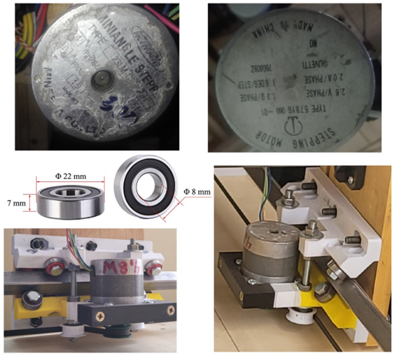
We also consider that a teacher already had some parts such as Step-by-Step motors that he was able to recover from an old photocopier and others bought at the "Baratillo" (second-hand objects).
To begin with, 12-millimeter plywood was obtained for the base, and double sides.
. 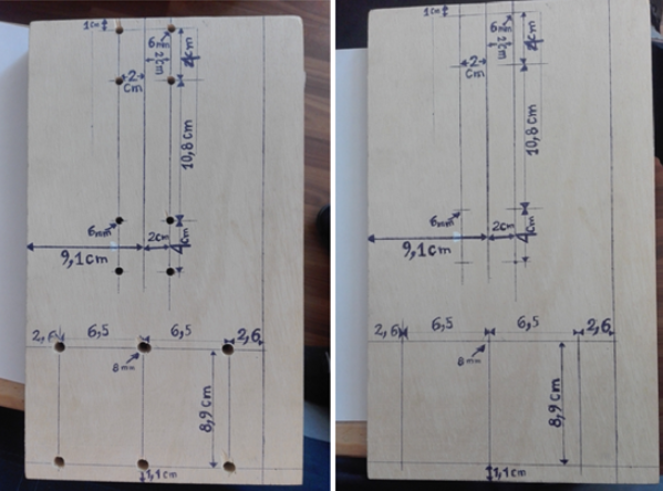
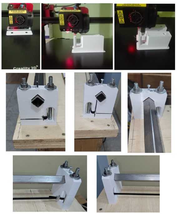
Once marked and put some measurements we start drilling and we start with the printing of the internal and external parts of the sides.
We get the necessary screws and the square tube that will be the crossbars, where the Z axis will go, in the following figure we see the installation of the attached tube with the necessary screws seen both from the external (left) and internal (right) part.

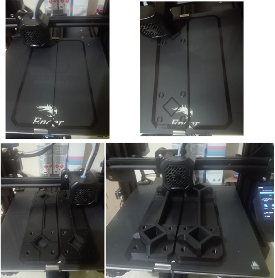
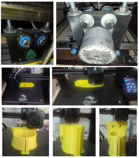
Now we will print the lower parts of the side tables where the stepper motors of the Y axis will also go
When we wanted to locate our motors, we saw that the model was for NEMA 17 motors but the motors we had were PAP NEMA23 motors so we had to reprint with the required size, but we didn't have much PLA material anymore so we had to print with all the material we had. Finishing the printing we integrate the 608 RS bearings with all the necessary screws, so that I can roll on the crossbars of the Y axis, which is also the square iron, we install the whole set on the side plates.
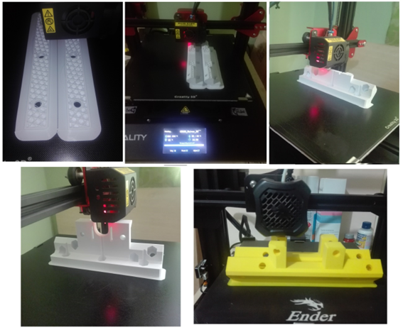
Now to be able to attach the Y-axis crosspieces to the base we require 4 support points, which we will print and install on our base board with the necessary screws, we also take advantage of placing the toothed belts for traction.
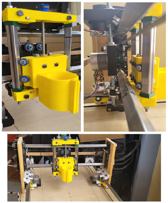
We will finish assembling the part of the X axis that integrates the assembly with many parts that belong to the Z axis, for this we print the parts of the PAP motor and the bearings.
Now we integrate the entire structure and we have our CNC router as follows.
Now we place the sacrificial bed with its presses to adjust our work piece.
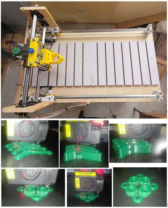
To finish the assembly of the machine we put the router and the work bit.
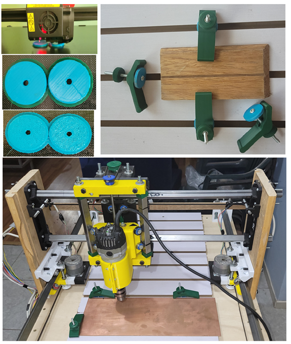
EXHIBIT: links
For exhibit work, see the next video. The video are going to edition mode and now placement other video in replacement....¡