Electronic Production
Group assignment:
- Characterize the design rules for your in-house PCB production process
- Extra credit: send a PCB out to a board house
Individual assignment:
- Make an in-circuit programmer that includes a microcontroller:
- Extra credit: customize the design
- ill and stuff the PCB
- Test it to verify that it works
- Extra credit: try other PCB processes
Basic Research
Electronic foundations.
Building circuits
An electronic schematic is the graphic representation of a circuit. It serves as a guide to build and debug that circuit, so it is essential that we know how to read and interpret schematics. Schematics can be small, simple circuit diagrams or large, complex designs that can span multiple pages.
Electronic schematics use symbols to represent the components of a circuit. And those components are connected to each other with lines that represent electrical connections.
The elements of a schema are purely symbolic and should be arranged in a way that makes them easier to read and interpret. When it comes time to build the circuit, the components need to be arranged in a way that makes it easier to connect them together.
Build circuits on breadboards
- Back in the early days of electronics, hobbyists and tinkerers would assemble their prototype circuits on wooden breadboards one, using wires and nails to attach components, now we have specially designed boards for prototyping circuits, but we still call them breadboards.
Using a breadboard is the easiest way to build and test new circuits. They hold circuit components in place and enable you to connect them without soldering, which is a process for permanently attaching electrical components together. Since breadboards don't use solder, that means the circuits are temporary, which makes breadboards great for building quick prototypes because you can easily change the circuit if something goes wrong. Breadboards come in a variety of shapes and sizes, but they all work in the same way.
You connect components to the breadboard by simply inserting their metal leads into holes. There are tiny little metal clamps inside of each hole, which hold the component in place and electrically connect it to certain other holes. I often use needlenose pliers to insert component leads into the breadboard, especially in crowded circuits. It makes things easier.
These holes are internally connected to each other lengthwise down the board, and they're used to distribute power to the circuit components and are often referred to as the power bus. The red line is typically connected to the positive voltage of the circuit's power supply, and the black lines are connected to ground or the negative supply voltage. I would recommend using a breadboard power supply like this one, which is connected to a wall adapter and then provides either 3.3 volts or five volts to the power bus on either side of the breadboard.
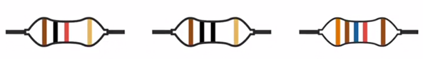
Resistors
Resistors are electronic components that have a specific amount of electrical resistance, and we can use resistors to control and direct the flow of electrons through circuits by limiting the amount of current that goes to certain parts of the circuit.
The most common type of resistors are called static resistors because they have a constant amount of resistance. It may not always be possible to find a static resistor with the exact resistance value that you want for a circuit because they're only manufactured in certain standardized values. So you'll need to pick among the resistors that you do have available to get a close alternative.
The list shown here contains some of the more commonly used resistor values. And as I build circuits throughout this course, I'll be choosing my parts from this list, which I've included in the exercise files for you to use as reference.
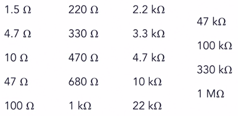
Common Resistor Statics Values
Resistors are passive components, which means they cannot produce any electrical power on their own. They only consume power by converting electrical energy into heat. That means they need to be physically large enough to dissipate all that heat. The size of a resistor package will depend on its power rating, with larger resistors being able to handle and dissipate more power.
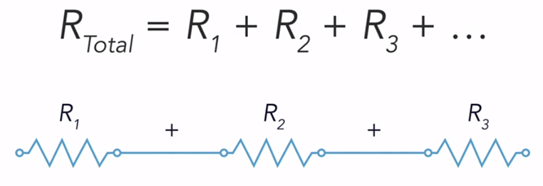
Resistors in series
Las resistencias conectadas en serie están unidas entre sí de extremo a extremo. En este arreglo, la resistencia total combinada de la serie de resistencias es igual a la suma de todas sus resistencias individuales. Podemos tratar esta colección de resistencias en serie, como una sola resistencia con un valor de resistencia mayor.
Omh's Law
Ohm's law makes the relationship between the voltage, current, and resistance of that resistor very simple.

Group Assigment
Individual Assigment