Mechanical Design, Machine Design
DESCRIPTION:We have the opportunity to be able to design and build a machine that allows us to practice with the tools of the laboratory or workshop and to be able to analyze our capabilities.The chosen project is to build a CNC router that from the experience of the previous tasks we see that it will help us to carry out different tasks of the FabAcademy.GROUP ASSIGNMENT: Once our project has been selected, we now give it certain restrictions, such as using the greatest number of components that we can acquire in specialized stores and local hardware stores in Cusco, although some, but very few, we will have to buy in Lima (normally); For the parts that we cannot find, we will use 3D printers with PLA material based.We also consider that a teacher already had some parts such as Step-by-Step motors that he was able to recover from an old photocopier and others bought at the "Baratillo" (second-hand objects).To begin with, 12-millimeter plywood was obtained for the base, and double sides.
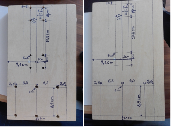
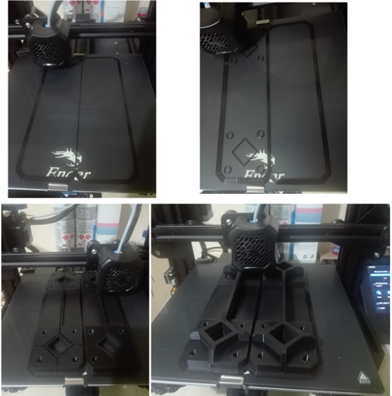
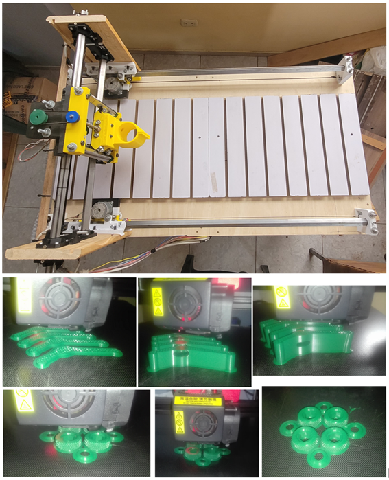
Once marked and put some measurements we start drilling and we start with the printing of the internal and external parts of the sides.
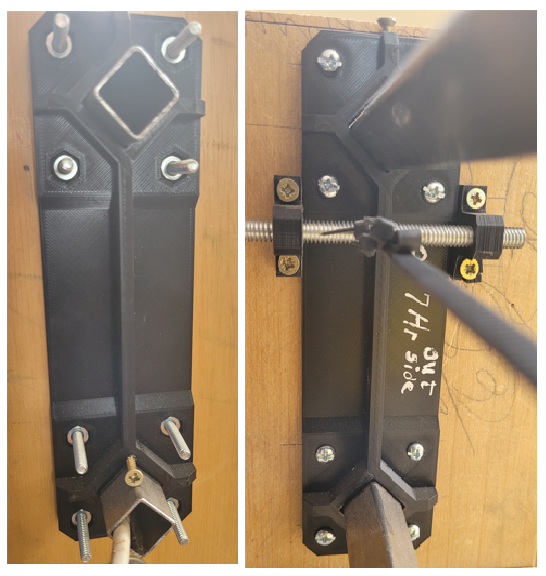
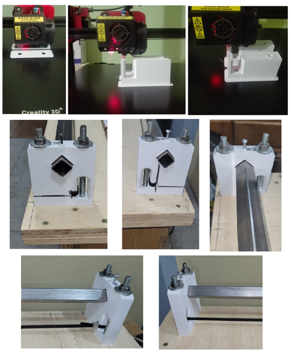
We get the necessary screws and the square tube that will be the crossbars, where the Z axis will go, in the following figure we see the installation of the attached tube with the necessary screws seen both from the external (left) and internal (right) part.
Now we will print the lower parts of the side tables where the stepper motors of the Y axis will also go
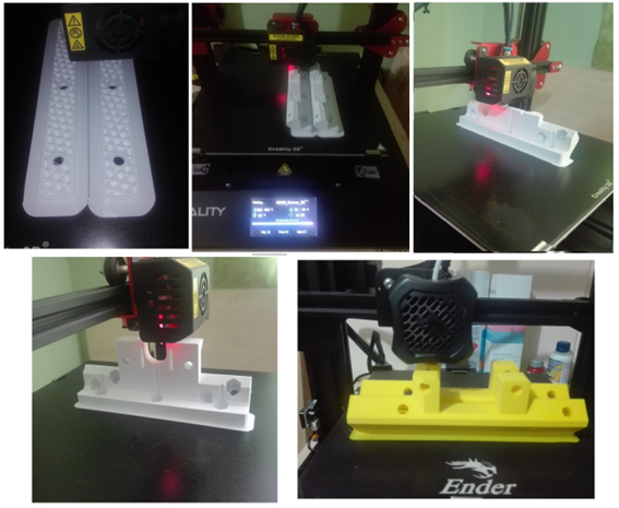
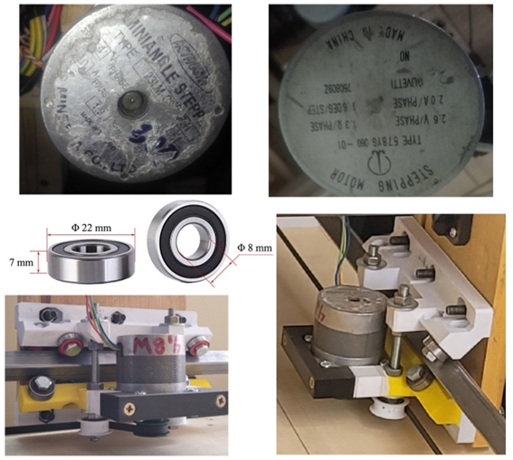
When we wanted to locate our motors, we saw that the model was for NEMA 17 motors but the motors we had were PAP NEMA23 motors so we had to reprint with the required size, but we didn't have much PLA material anymore so we had to print with all the material we had. Finishing the printing we integrate the 608 RS bearings with all the necessary screws, so that I can roll on the crossbars of the Y axis, which is also the square iron, we install the whole set on the side plates.
Now to be able to attach the Y-axis crosspieces to the base we require 4 support points, which we will print and install on our base board with the necessary screws, we also take advantage of placing the toothed belts for traction.
We will finish assembling the part of the X axis that integrates the assembly with many parts that belong to the Z axis, for this we print the parts of the PAP motor and the bearings.
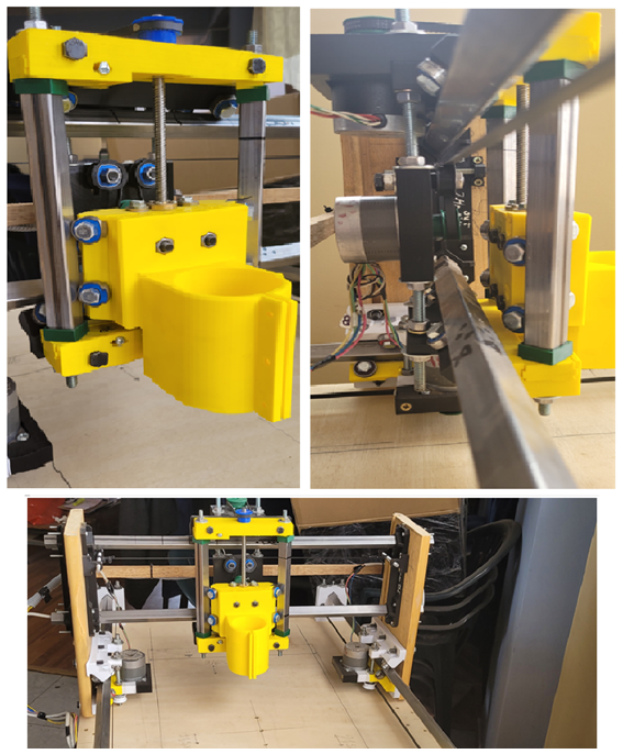
Now we integrate the entire structure and we have our CNC router as follows.
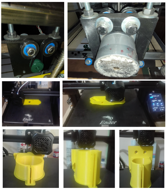
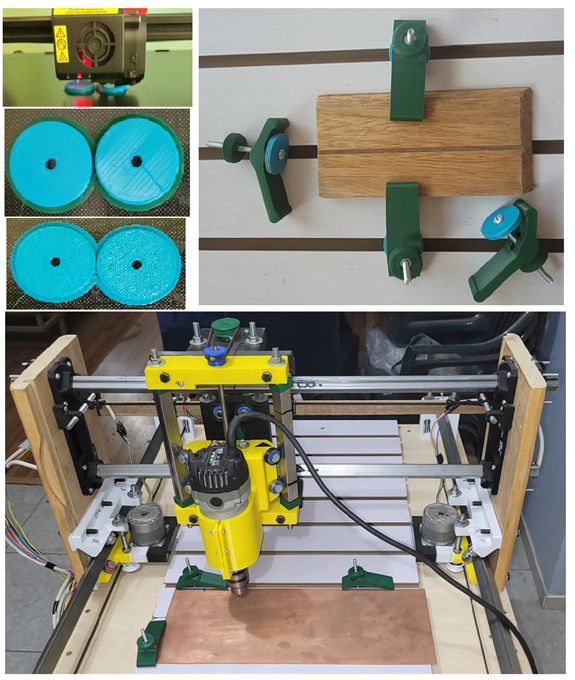
Now we place the sacrificial bed with its presses to adjust our work piece.
To finish the assembly of the machine we put the router and the work bit.
INDIVIDUAL ASSIGNMENT:
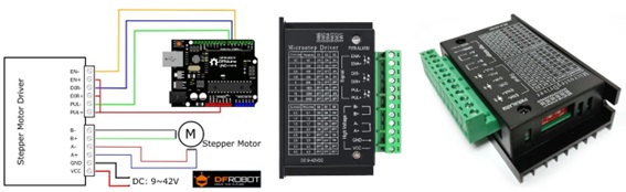
I was in charge of the electronic part of the machine, first and foremost the controllers for the PAP motors, which in this case we used the TB6600 Driver.
This professional bipolar stepper motor driver is based on the TB6600 chip and allows motors to be controlled up to 3.5A per channel (4A max). This driver has adjustable current limiting, overcurrent protection and 7 different microstepping resolutions.
It is compatible with microcontrollers like Arduino and others that can generate 5V pulse signals. The TB6600 supports a wide range of input voltages from 9 to 42V DC. It is capable of providing up to 3.5A of current continuously and 4A of peak for short periods of time. In this way you can control a wide variety of motors.
The controller supports direction and pitch control as in all controllers of this type. It can also be configured for microstepping via included microswitches. There are 7 possible values: 1, 2 / A, 2 / B, 4, 8, 16 and 32 as well as 8 positions for current adjustment: 0.5A, 1A, 1.5A, 2A, 2.5A, 2.8A, 3.0A and 3.5A. All signals are internally shielded by high-speed optocouplers to prevent interference and improve control circuit isolation. It comes assembled in a metal case for measured cooling.
Characteristics:
• Control signals: 3.3 to 24V
• Maximum power: 160W
• Supports 7 types of adjustable micro steps
• Micro Step: 1, 2/A, 2/B, 4, 8, 16, 32
• Operating temperature: -10 to 45℃
• Humidity: No condensation
• Dimensions: 96x56x33 mm
• Weight: 200 grams
• Stepper motor driver for Nema 17, Nema 23, Nema 24
• Supply voltage: 9 to 42Vdc
• Input current: Min. 1A Max. 5A
• Supports 8 types of current control
• Current output: 0.5 to 3.5A (adjustable)
• The interface adopts high-speed optocoupler isolation.
• Automatic semi-flow to reduce heat
• Large area heat sink
• Anti-high frequency interference capability
• Input anti-reverse protection
• Protection against overheating, overcurrent and short circuit
• Operating temperature: -10 to 45 °c
• Weight: 200 grams
We require 4 of these motors for the movement, two for the Y axis, one for the Z axis and another for the X axis, which with the help of the GRBL firmware, which is a software prepared to transform the GCODE file into motor movement and is used on a wide variety of CNC machines such as routers, laser engravers and so on, it's relatively easy to get up and running and they work really well. We are used to seeing it mounted together with an Arduino UNO board, as is the case in which we replicate it since we found good information about it.
We install as follows.
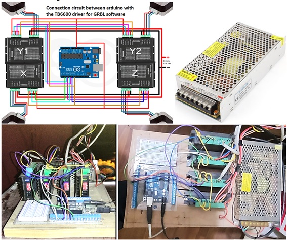
We use a commercial 12 volt 10 amp LED switching power supply with aluminum housing, with AC 110V/220V +/-15% input and DC 12V/10A/120W output. 450g
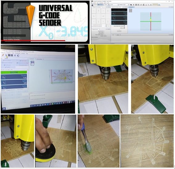
To control the machine we use the UGS (Universal Gcode Sender) program which is a fully featured gcode platform used to interface with advanced CNC controllers such as GRBL, TinyG, g2core and Smoothieware. Universal Gcode Sender is a stand-alone Java application that includes all external dependencies and can be used on most Windows, MacOSX, or Linux computers.
Characteristics:
• Cross platform, tested on Windows, OSX, Linux and Raspberry Pi.
• 3D Gcode viewer with color-coded line segments and real-time tool position feedback.
• Duration estimates.
• Support for Gamepads and Joysticks
• Web pendant interface
• Over 3,000 lines of unit test code and another 1,000 lines of comments documenting the tests.
• Configurable gcode optimization:
o Delete comments.
o Truncate decimal precision to a configurable amount
o Convert arcs (G2/G3) to line segments
o Remove blank spaces
We install UGS on the machine and try with the logo of the institution that is already working.
created with
Web Design Software .