Before connecting any load to our board, we must know the amount of voltage and current that they need in order not to damage the electronics, more specifically the Atmega 328P microcontroller.
In this assignment we are asked to know the power consumption of an output device and also to connect this output device to the microcontroller board we designed earlier and program it to do something.
I will review the most common motors and I will be controlling their movements from my electronic card.
DC motor (direct current)
In general, electrical power can be supplied by direct current (DC) sources and by alternating current (AC) sources.
An electric motor is a device that converts electrical energy into mechanical energy of rotation, being able to work with AC or DC (DC).
The most notable difference between a DC motor and an Alternating Current (AC) motor is that the DC motor requires a commutator device in order to function.
Both AC and DC motor are used for certain tasks, so there is no one that is better or worse. Each one has its advantages and disadvantages, depending on what it is used for.
The use of the two types of electric motors is innumerable, from the toy car, through the appliances in our home, to industry or means of transportation, among others.
The DC motor moves by creating a magnetic field that is powered by direct current. Power usually comes from batteries or some other external source.
Many of them already have a power transmission system such as a gearbox which allows them to increase their output torque (“force”). One of its advantages is that its speed can be precisely controlled. Since they can be reversed, stopped and started immediately. 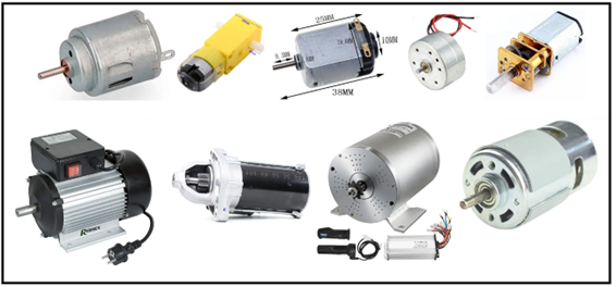
Functioning.
Regularly this type of motor is equipped with 2 magnets, (used in small motors) also known as stators. Which produce a magnetic field around the axis, inside we will have an axis with the commutator and the connection with the direct current source (it can rotate freely).
Likewise, using a carbon system or a pressure plate. This is a conductive material and thanks to a spring it is always in contact with the axis.
Once the commutator system is ready, the cables through which electric current will pass are added, thus generating a magnetic field. Which will align with the magnetic field of the stator.
When current passes through the wire or coil that is placed between the south and north poles of the magnet. Likewise, the generated field interacts with the field of the magnet applying a torque.

When a current-carrying conductor is placed in a magnetic field, this is when mechanical force is created. The direction of this force is determined by Fleming's rule, also known as the left-hand rule.
This rule tells us that when there is a charge in motion, which moves in the direction of the thumb, a magnetic field is generated in the direction of the rest of the fingers.
This rule is used mainly in electromagnetism, to determine the movement of a conductor.

Types of DC motors
With brushes:
This type of motor is one of the oldest that exists, since it is powered by direct current and internally commutated. It is built by an axis, brushes (hence its name) and a rotor. And it is the polarity and the charge of the brushes themselves who are in charge of controlling the speed and direction of the motor.
Brushless:
Also known as a synchronous DC motor, one of the characteristics is that they do not have a commutator, unlike a brushed motor, for example. These are the most used thanks to their efficiency. To control their direction and speed, they include specialized circuits.
In addition, they are built in the same way as brush motors, only that, to improve their efficiency, magnets are mounted around the rotor. That is to say, that the magnet is in the windings of the stator and the rotor.
DC motors have a relatively short life time, because the brushes have sliding contact between the brush and the commutator, they produce sparks, they cannot be operated in conditions where there is gas, for example, and therefore cause mechanical wear.
The armature is damaged and the shaft vibrates, as its speed increases, its maintenance is expensive many times.
Depending on the size of these types of motors and the force they require to move some weight (load) will be the current consumption they need to work, so first we will measure this current.
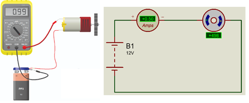
We measure the consumption current of our motor.

The pins of our Atmega only provide us with a maximum of 40 mA according to its datasheet, so we will require a current amplifier such as a medium power output transistor that allows us to control its speed by means of PWM for example or also with a relay if we just want to start and stop the engine in an instant of time.

These two circuits only allow me to move the motor in one direction, if I wanted to change the direction of rotation and have good current we must have an H bridge, which already comes many times in integrated circuits or also in cards like the L293D with two bridges h inside.
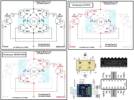
H-Bridge Operation:
Applying a positive signal to the input marked FORWARD turns transistor Q1 on. Current from Q1 flows through the bases of transistors Q2 and Q5, causing motor terminal a to receive a positive and terminal b to receive a negative (ground).
If instead a signal is applied to the REVERSE input, transistor Q6 is made to conduct, which closes its current through the bases of transistors Q4 and Q3. In this case, the positive is applied to the motor terminal b and the negative (ground) is applied to the motor terminal a.
One of the very important things to keep in mind when controlling this circuit is that the FORWARD and REVERSE signals must never coincide. If this happens, the transistors Q2, Q3, Q4 and Q5 will close the circuit directly between the positive of the power supply and ground, without going through the motor, so it is certain that the Emitter-Collector current capacity and the transistors will be exceeded. they will be damaged forever. And if the power supply is not protected, it can also suffer significant damage.
For our assignment we will use the L298N which has higher power.
H Bridge Module L298N for the control of 02 DC Motors or 01 Stepper motor (PaP).
Technical characteristics:
• Integrated: L298N.
• Channels: 2 (supports 2 DC motors or 1 PAP motor).
• Logic Voltage: 5V.
• Operating Voltage: 5V-30V.
• Current consumption (Digital): 0 to 36mA.
• Current capacity: 2A (peaks up to 3A).
• Maximum power: 25W.
• Weight: 30g.
• Dimensions: 43mm (Length) x 43mm (Width) x 27mm (Height).

We will develop a program that allows to control the direction of rotation and the speed of a DC motor with the help of buttons.
Program.
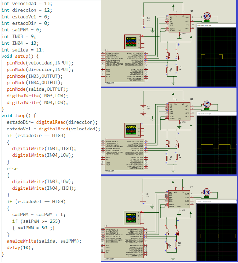
The speed change according to the PWM cutting angle is represented very well.
We set it up with our card and it works very well.
A Stepper motor (PaP hereinafter) differs from a conventional DC motor in that its axis can be positioned in fixed positions with specific angles or known as steps, being able to maintain the position. This peculiarity is due to the construction of the motor itself, having on one side the rotor made up of a permanent magnet and on the other the stator built by coils, when feeding these coils the pole of the magnetic post rotor will be attracted with respect to the pole generated by the coil and it will remain in this position attracted by the coil's magnetic field until the coil stops generating the magnetic field and another coil is activated making the rotor move forward or backward, varying the magnetic fields around the axis of the motor and making it this turn.
Operation: PaP engines can be characterized from different points of view, but this time we will classify them by the number of terminals. According to their terminals we have the Bipolars that are generally 4 terminals and the unipolars that have 6 terminals or 5 terminals if we join the central common of both coils.
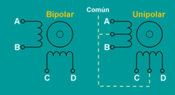
Bipolar: This type of motor has two independent windings one from the other, to control this motor it is necessary to invert the polarity of each of the coils in the proper sequence, for this we will need to use an "H" bridge or driver type L293b to each coil and in this way we will have a sequence table to control its operation.
Each inversion in polarity causes the movement of the axis, advancing this one step, the direction of rotation corresponds to the direction of the sequence of steps, for example, to advance clockwise the sequence would be 1-2-3-4, 1-2-3-4.... and for counterclockwise it would be; 4-3-2-1,-4-3-2-1...

Unipolar: The unipolar motor normally has 5 or 6 cables depending on whether the common is connected internally or not, to control this type of motor there are three methods with their corresponding coil ignition sequences, the common will be connected to +Vcc or ground depending on the control circuit used and then we will only have to feed the correct coil so that the motor advances or goes backwards as we advance or go back in the sequence.

The simplest circuit to be able to work with these motors would be the ULN2008 that provides up to 600mA per channel, for more power a bank of power transistors can be used.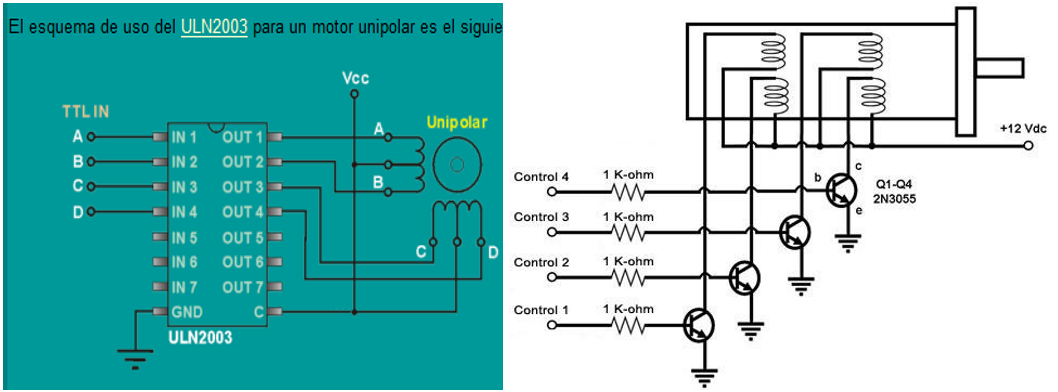
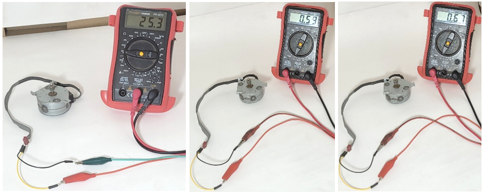
We measure the resistance of the motor coil and its current at 9V and 12V.
I will implement a program that allows to control a unipolar stepper motor, where its speed and direction of rotation are varied based on the L298 seen previously, the leds.
Program: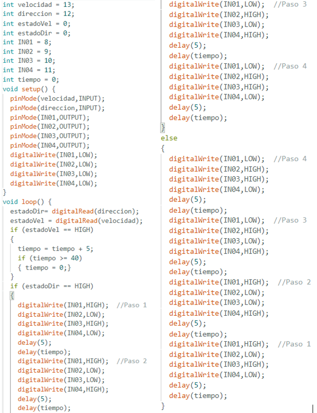
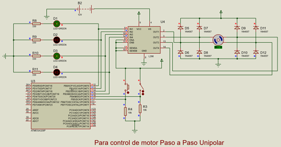
Implemented with the card and it turned out fine, the protection diodes are already on the board.
A servomotor is an electric motor that has an electronic control card that allows us to control it, both in speed and in position.
A servomechanism is a mechanical actuator, generally a motor, although not exclusively, that has enough control elements so that its mechanical actuation parameters can be monitored, such as its position, speed, torque, etc.

They constitute a better performance and precision compared to drives through frequency converters, since these do not provide us with position control and are ineffective at low speeds.
A servomotor is one that contains an encoder inside, known as a decoder, which converts the mechanical movement (axis rotations) into digital pulses interpreted by a movement controller. They also use a driver, which together form a circuit to command position, torque, and speed.
Servo for modeling: 
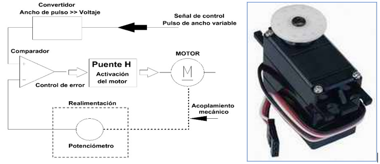
A servomotor is made up of:
An electric motor: Which is responsible for generating movement through its axis.
A control system: This system allows you to control the movement of the motor by sending electrical pulses.
A regulation system: It is formed by gears by which you can increase the speed and torque or decrease them.
A potentiometer: It is connected to the central axis and allows you to know at all times the angle at which the motor axis is located.
How a servo motor works
Servo motors are controlled by sending a variable-width electrical pulse, or Pulse Width Modulation (PWM), through the control wire. There is a minimum pulse, a maximum pulse, and a repetition rate.
Typically, a servo motor can only turn 90° in any direction for a total movement of 180°. Motor neutral is defined as the position where the servo has the same amount of potential rotation in both a clockwise and counterclockwise direction.
The PWM sent to the motor determines the position of the axis, and is based on the duration of the pulse sent through the control wire; the rotor will rotate to the desired position.
The servo motor expects to see a pulse every 20 milliseconds (ms) and the length of the pulse will determine how far the motor rotates. For example, a 1.5ms pulse will cause the motor to rotate to the 90° position.
If the time is less than 1.5ms, it moves counterclockwise to the 0° position, and if the time is more than 1.5ms, the servo will rotate clockwise toward the 180° position.
When the servos are commanded to move, they will move to the position and hold that position. If an external force pushes against the servo while the servo is holding a position, the servo will resist moving out of that position.
The maximum amount of force that the servo can exert is called the servo torque. However, the servos will not hold their position forever; the position pulse must be repeated to tell the servo to stay in position.

Types of servo motors
Servos come in many sizes and in three basic types: positional rotation, continuous rotation, and linear.
Positional Rotation Servo: This is the most common type of servo motor. The output shaft rotates approximately half a circle, or 180 degrees. It has physical stops placed on the gear mechanism to prevent it from rotating beyond these limits to protect the rotation sensor.
These common servos are found in remote controlled cars and water planes, toys, robots, and many other applications.
Continuous Rotation Servo: This type is very similar to the common positional rotation servo motor, except that it can rotate in any direction indefinitely. The control signal, instead of adjusting the static position of the servo, is interpreted as the direction and speed of rotation.
The range of possible commands causes the servo to rotate clockwise or counterclockwise as desired, at a variable speed, depending on the command signal. This type of servo can be used in a radar dish if it is mounted on a robot. Or it can be used as a drive motor in a mobile robot.
Linear Servo: This is similar to the positional rotation servo described above, but with additional gears (usually a rack and pinion mechanism) to change the output from circular to reciprocating. These servos are not easy to find, but can sometimes be found in model shops where they are used as actuators on larger model airplanes.
What are servo motors for?
Servo motors are used in applications that require rapid speed variations that could cause excessive motor heating, such as industrial robotics, manufacturing with automation systems, and computer numerical control (CNC) machining applications, among others. others.
Most common applications of servos:
• In industries they are used in machine tools, packaging, factory automation, material handling, print converting, assembly lines and many other demanding applications: robotics, CNC machining or automated manufacturing.
• They are also used in radio-controlled aircraft to control the position and movement of elevators.
• They are used in robots due to their smooth on and off and precise positioning.
• They are also used in the aerospace industry to maintain hydraulic fluid in their hydraulic systems.
• Used in many radio controlled toys.
• Used in electronic devices such as DVD and disc players to expand or play disc trays.
• They are also used in automobiles to maintain vehicle speed.
Work on a program that controls the position of a servo motor that receives data from the serial monitor.
Program:
Simulation: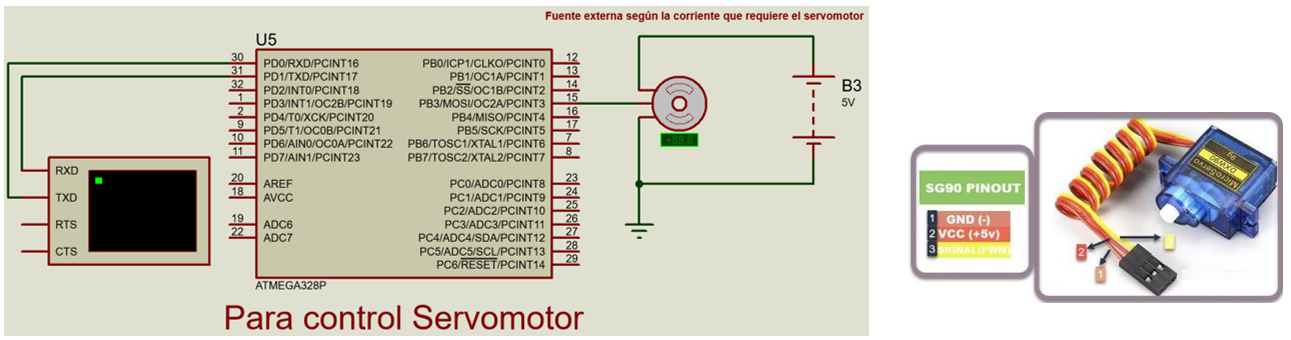
We implemented it and it is working very well. Due to the amount of current required by the servo motor greater than 40mA (Atmega 328P pin), we prefer to use an external power supply.
(video de servo).
created with
Website Builder .