To work with microcontrollers we should know them both from the outside and inside them, at least the essentials.
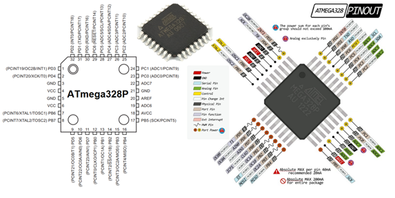
EXTERNAL PART: You must know the form of packaging as in this case it is SMD and the name of the pins as I leave you in the image below.
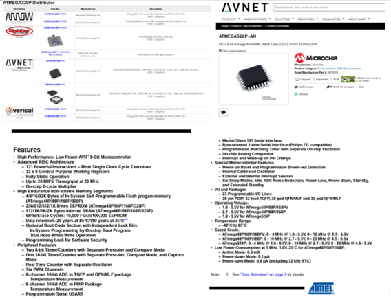
INTERNAL PART: we know it through the data sheet provided by the company that builds it, (I always say that it is the birth certificate of the electronic component).
When reviewing the data sheet, it provides us with the following general data.
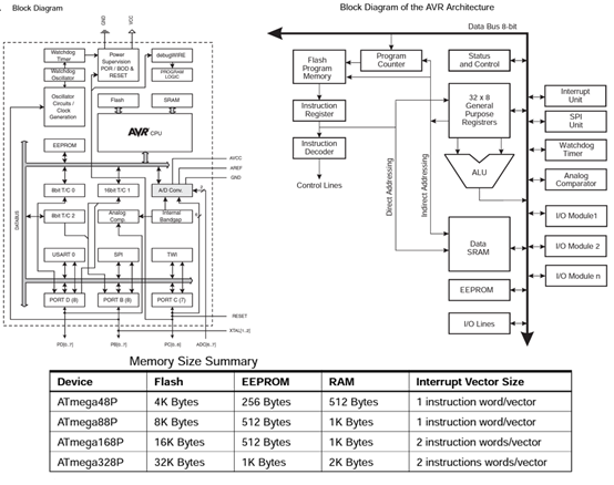
It is also important to know its internal diagram and at least know the main operation of some parts.
Microcontrollers differ in the way they treat data and this is based on their architecture. I think this difference gave way to the massification of microcontrollers and embedded systems. According to the story we have two architectures which are Von Neumann and Harvard, the Von Neumann architecture was designed by the renowned physicist and mathematician John Von Neumann in the late 1940s, and the Harvard architecture was based on the original Harvard Mark computer I based on relays.
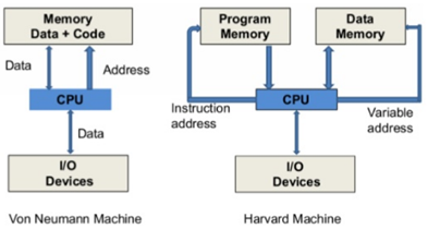
In the Von Neumann architecture all the elements of the program (information) both data and instructions are stored in all memory;
In the Harvard architecture, memory is divided into two memories, one memory for data and another memory for instructions.
In general memory can be accessed once per clock cycle, a Von Neumann architecture requires at least two clock cycles to execute an instruction whereas a Harvard architecture can execute instructions in a single clock cycle leading to a much simpler and cleaner design for a CPU (central processing unit) than one implemented using a Von Neumann architecture.
CPUs are classified as CISC or RISC, depending on their internal organization. CISC refers to computers with a Complex Instruction Set Computers (CISC) and RISC is to refer to computers with a Reduced Instruction Set Computers (RISC).
A RISC architecture has few instructions and they are generally the same size; in the CISC there are too many instructions with different sizes and formats, which can occupy several bytes, one for the opcode and the others for the operands.
The task performed by one CISC instruction may require several RISC instructions. In contrast, the hardware of a RISC processor is so simple that it can be implemented in a fraction of the integrated circuit footprint of a CISC processor.
In microcontrollers we can highlight some important elements, such as the logical-arithmetic unit or ALU, which allows operations, general purpose registers, input and output modules, among others. Registers are basically memory units that we can access to read or write data.
There are also specific-purpose registers, such as timers and those that control serial communication. The registers of specific purpose, in addition to handling information allow configuring and managing hardware, such as analog inputs, are very important.
The ATmega328p that we are using has registers that are connected to the input/output ports, each port has a specific name and its associated registers, in fact the 328p has ports B, C and D, and each port has 8 pins where a representation to address them would be PBx, PCx or PDx, where P is for port, B, C or D is the set to which it belongs and x is the pin number but depending on the package there may be a restriction on the number of pins To the exterior.
Each pin can have multiple functions, such as PWM generation, or ADC capabilities, PORTB pins 6 and 7 are the input pins for the crystal oscillator, and PORTC pin 6 corresponds to the reset button.
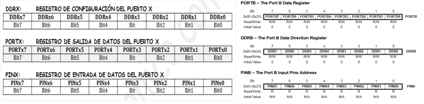
To start working with the ports we have to know the registers that control it or better are dedicated to each port, as we have already seen, each pin is an input or an output and can be determined in the DDR register, (1 output, 0 input). . In the case of the uC there are DDRB, DDRC and DDRD.
The PORT register controls whether the pin is high (1) or low (0) and is checked on the outer pins with voltage levels 5V high and 0V low.
The PIN register allows you to read the state of a pin. (read only).
Each bit in these registers corresponds to a single pin; for example, the least significant bit of the DDRB, PORTB, and PINB registers reference pin PB0 (digital pin 12) and the most significant bit of the registers reference pin PB7 (digital pin 8).
Setting a PIN
DDRB=0b11111111; Set all pins of Port B as Output.
DDRB=0b00000000; Set all pins of Port B as Input.
DDRB=0b00001111; The High pins as Input and the rest as Output.
Typing a PIN
PORTB = 0b11111111; All Port B pins with a 5v output.
PORTB = 0b00000000; All pins of Port B with a 0v output.
PORTB = 0b00001111; High pins to 0v and Low pins to 5v.
Reading a PIN
Value = PINB0; The logic state of the PB0 pin is written to Value.
Value = PINB; The logical state of all Port B is written to Value.
In order to enable the PULL-UP resistor on a given pin, it is necessary that said pin be configured as an input and then write a logic "1" in the PORTX output register. And automatically the PULL-UP resistor is enabled.
Advantages and Disadvantages that it offers us when using the records:
Disadvantages:
• The code is much more difficult to debug and maintain, and it is much more difficult to understand. It only takes a few microseconds for the processor to execute code, but it could take hours to figure out why it's not working and fix it.
• It is much easier to cause unintended malfunction by using direct port access. With DDRD = B11111110, pin 0 should be left as an input. Pin 0 is the receive (RX) line on the serial port. It could be very easy to cause the serial port to stop working by changing pin 0 to an output.
Advantages:
• You can change state pins very fast, in fractions of microseconds. The digitalRead() and digitalWrite() functions are each made up of about a dozen lines of code, which translates into a few machine instructions.
• Each machine instruction requires one clock cycle at 16MHz, which can add a lot of time in highly time-dependent applications. The PORT Registry can do the same job in far fewer work cycles.
• Sometimes we need to configure many pins at exactly the same time. So using the digitalWrite(10,HIGH) functions, followed by the digitalWrite(11,HIGH) function, will cause pin 10 to go high several microseconds after pin 11, which can confuse digital circuitry connected to the pin. Arduino, whose operation depends on the precise time of the change of those bits.
• If you are running out of memory, these tricks can be used to make your code smaller. Using this method requires far fewer bytes of compiled code than looping through each pin one at a time.
We will make use of these registers with an example: We will generate a counter from 0 to 9 in a 7-segment display.
Program:
int count = 0;
void setup() {
DDRD = B11111110; // We use seven bits from port D as outputs.
DDRB=B00000011; // We use two bits from port B as outputs.
}
void loop() {
if (count >= 10)
{
count = - 1;
}
count = count + 1;
switch (to count)
{
case 0:
PORTD= B01111110; break;// here we print 0.
case 1:
PORTD=B00001100; break; // here we print 1.
case 2:
PORTD=B10110110; break; // here we display 2.
case 3:
PORTD=B10011110; break; // here we display 3.
case 4:
PORTD=B00001100; break; // here we display 4.
case 5:
PORTD= B11011101; break; // here we display 5.
Case 6:
PORTD= B11111010; break; // here we print 6.
Case 7:
PORTD=B00001100; break; // here we print 7.
Case 8:
PORTD= B11111110; break; // here we print 8.
Case 9:
PORTD= B11011110; break; // here we print 9.
default:
PORTD=B00000000; break; // here off.
}
PORTB=B00000000; //Turn on the display
delay(100);
PORTB=B00000001; // We turn off the display
}
Simulation:
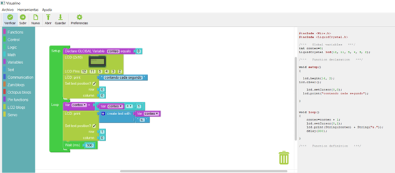
To program our card, I was working with graphic software such as MODKIT, but it didn't seem very practical to me because it has few tools, unlike other programs such as Visualino, which provides us with more tools (http://www.visualino.net/index. es.html) and also shows us the program in text to be able to check its operation in the Arduino IDE if you prefer.
We develop the following program in Visualino and check it with our card by passing it to the Arduino IDE.
We copy the code on the right and with the help of the Arduino IDE we program our board and test it.
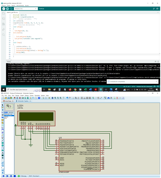
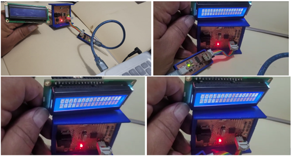
The presentation of messages turned out very well.
created with
HTML editor .