In this assignment we must build a circuit based on a microcontroller with a basic operation, for this part I will use a software that I will just know, which is kiCAD.
Jean-Pierre Charras in 1992 started the development of a free software application for Electronic Computer Aided Design (ECAD) to develop electronic circuits and called it KiCad, this multiplatform tool runs on Windows, Linux and Apple MacOS and is published under The GNU GPL open source license is free and open source software.
The main tools in the software suite are used to create schematics, printed circuit diagrams, SPICE simulations, nomenclature, illustrations, Gerber files, and 3D views of the PCB and its components.
With the schematic editor you can create unlimited designs; There are no paywalls to unlock features. It has an official library for schematic symbols and a built-in schematic symbol editor which help to get started on designs quickly.
Make professional PCB designs with up to 32 copper layers. KiCad now has a push and push router that is capable of routing differential pairs and interactively adjusting trace lengths.
KiCad includes a 3D viewer that you can use to inspect your design on an interactive canvas. You can rotate and pan to inspect details that are difficult to inspect in a 2D view. Multiple rendering options let you modify the aesthetic appearance of the dashboard or hide and show features for easy inspection.
We can find a tutorial at https://docs.kicad.org/4.0/es/getting_started_in_kicad/getting_started_in_kicad.pdf
PROGRAM INSTALLATION
It can be downloaded from https://www.kicad.org/download/ in my case it will be downloaded for Windows.
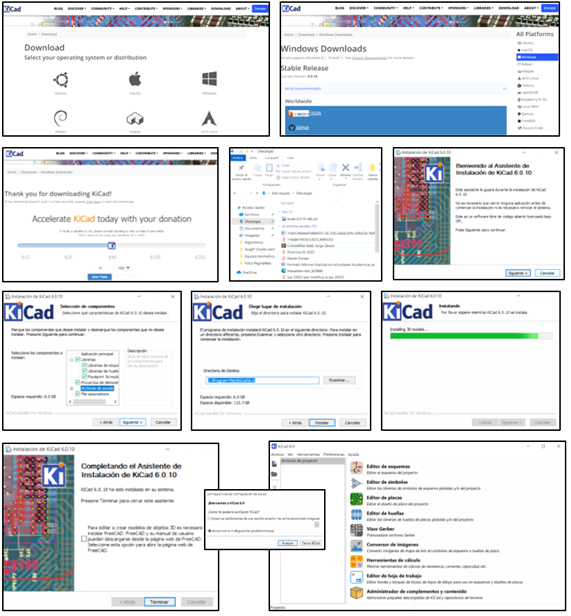
Until this moment we finished the installation of KiCAD, now we can work on the design.
CREATION OF THE CIRCUIT
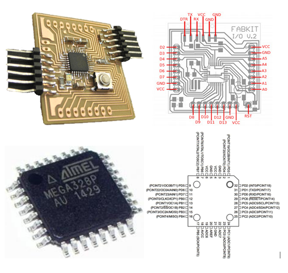
I reviewed several models on the internet, I found some works already done under the name of "Fabduino" and "FabKit V02" which are works of other groups, but there was a lack of a 5V voltage regulator for the Mega 328P microcontroller, so I could use the card with an external source, so we will have to improve the design by also leaving the serial communication available.
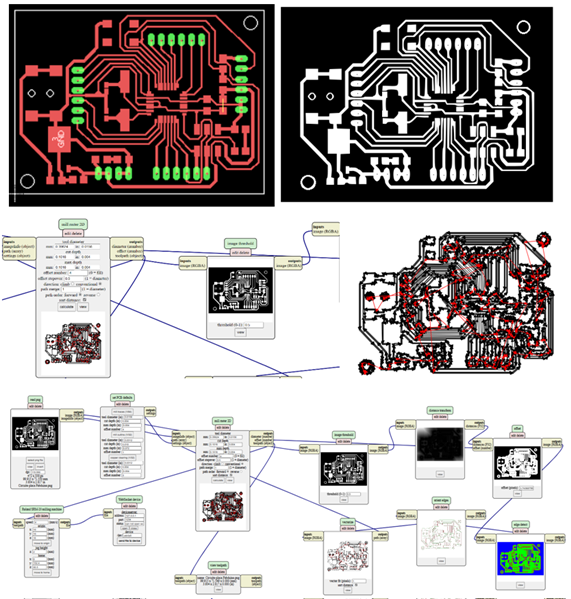
We will start the design in KiCAD and after the evaluation of the electrical rules we go on to the design of the PCB which we show the first proposal, but we saw that it is too big for us.
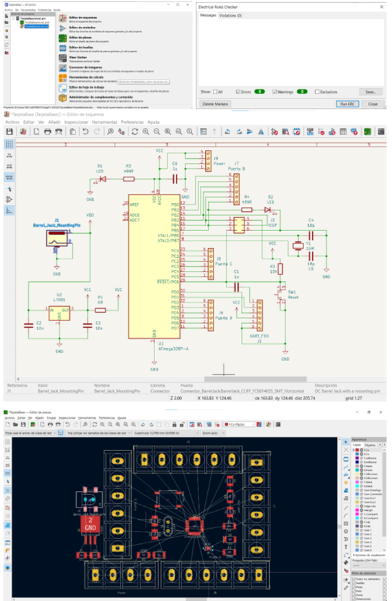
Then, adjusting the size of the components to smaller blades, it was possible to make the following circuit that was prepared for the MonoFab as we did in assignment 5 "Electronic Production".
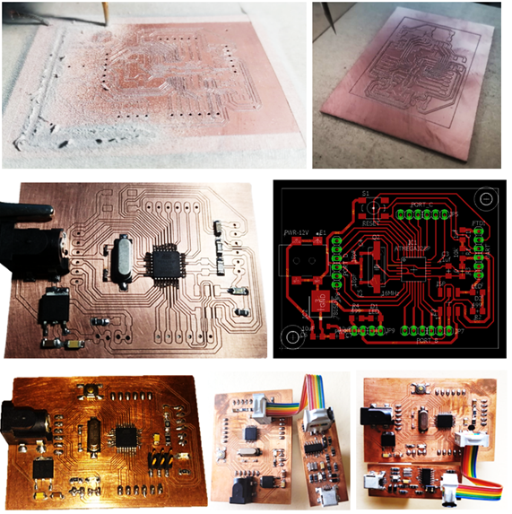
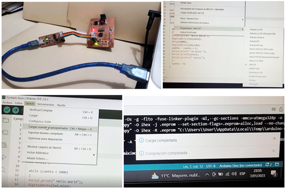
Now we have what is necessary to make a basic application based on a microcontroller, we will use the ICSP programmer that we did in assignment 5 “ELECTRONIC PRODUCTION,” to program the Atmega 328P microcontroller but first we will make the code.
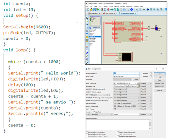
SIMULATION
The basic code that we make sends "Hello world", the led flashes 100 ms, also adds the number of times the message is sent.
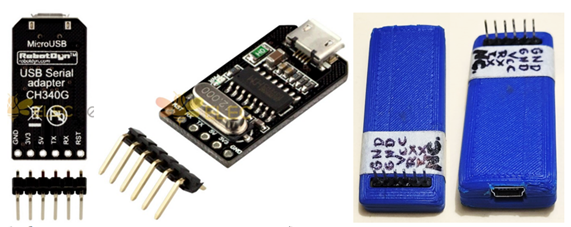
In order to receive the data from our card to the computer we require the respective communication from the serial port of the Atmega 328P, for this we use a USB-SERIAL TTL converter that will be connected to the PC, to avoid short circuit problems we made an encapsulation that allows to have the terminals (pins) available to connect it with the main card.
To finish this assignment we will record the program, then we will test its operation.
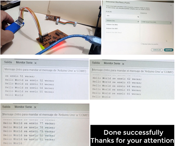
Everything went very well, I finished the test successfully.
created with
Website Builder .