For this assignment, the objective is to implement an ICSP programmer based on an Attiny family microcontroller. But before starting we must know the equipment to use in this case the MonoFab SRM-20.
The SRM-20 offers a compact size and powerful functionality at an affordable price. Producing realistic parts and prototypes is made simple and convenient with a device that fits in any office, classroom, or home. For users looking for advanced milling skills without the need to be experts, the SRM-20 is the most accurate and easiest to operate router in its class.


This Monofab SRM-20 belongs to the Roland company, on its website you can find more specifications and characteristics of this machine. (https://www.rolanddga.com/en-la/products/3d/srm-20-small-milling-machine).
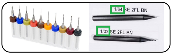
FIRST: We will carry out some tests using the 1/64 (0.4 mm) cutters to make the tracks and the 1/32 (0.8 mm) cutter to make the cuts of the plate, whether of one type or another.
We have to know how exactly the cut is made to define the thickness of the tracks, as well as the depth at which we have to work to define the routing of the PCB board well.
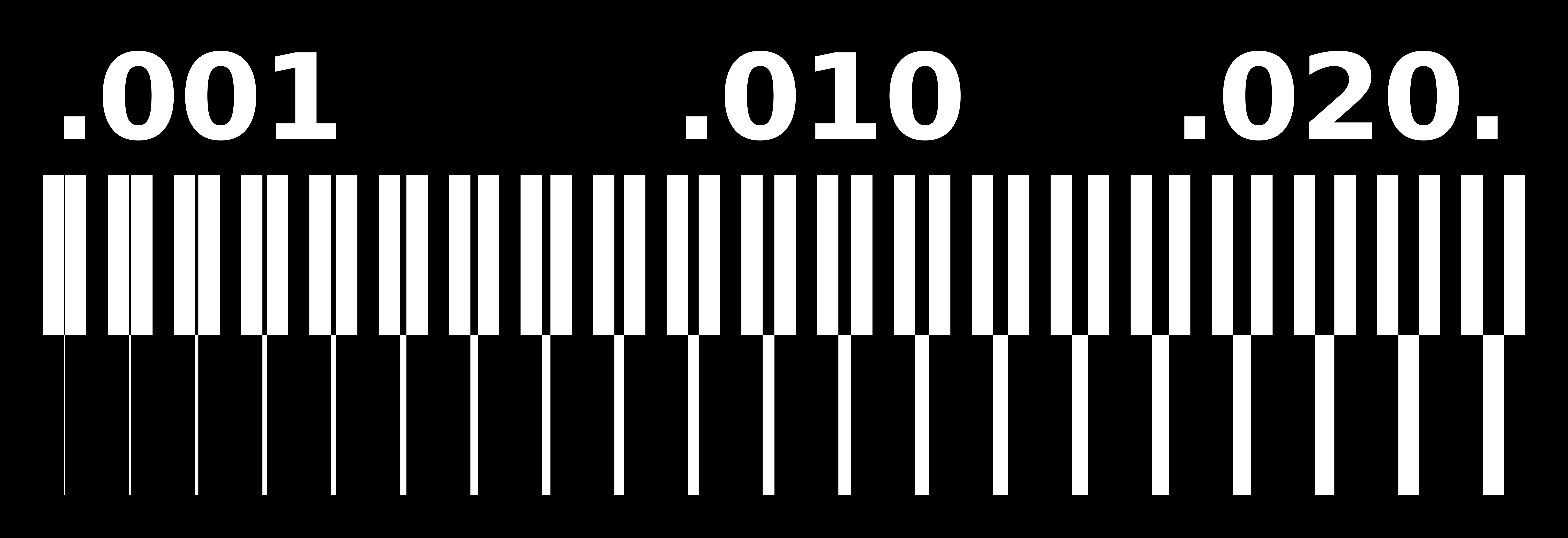
To determine these parameters we will work with the model provided at http://academy.cba.mit.edu/classes/electronics_production/linetest.traces.png.

To generate the gcode and the machine understands it, we use the Mods software that can be entered at http://mods.cba.mit.edu/;
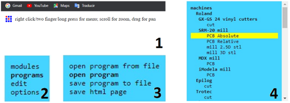
Once the program opens we will load the .png image that we want to route.
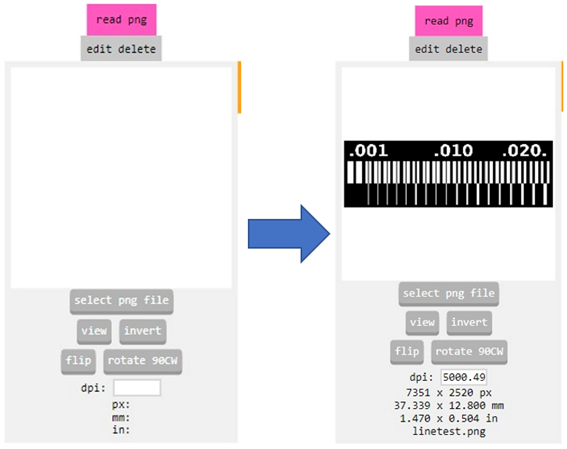
Then we configure the parameters to be able to make a good trace on the PCB.
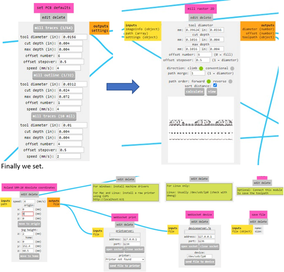
Below we show the entire process that we will repeat with each .png image in order to obtain the gcode.
With the gcode ready we can use the control software of the MonoFab machine, previously we have to place the "martyr" on the base (piece of melamine), without forgetting to place the cutter to use, which is the 1/64'' and On the "martyr" we will place the PCB board on which we are going to work.
We open the control program, we locate the initial point of work on the PCB board with the help of the cursors and we mark it as "zero point machines" starting point, we load our gcode and we make sure that this in the file extension is the correct (.RML) and the displacement is done in mm, to finish, we adjust the percentage of displacement and the RPM of the motor for the cut.

We looked at the first results, but they weren't very encouraging, so we adjusted the ground speeds as well as the engine revs, as well as the depth in the passes to finally find a correct configuration to work with the MonoFab.

SECOND:
In this part we have to develop or implement the generic ICSP programmer to be able to program microcontrollers in general for any type of project that we develop.
Going through the internet we found a programmer's proposal (http://fab.cba.mit.edu/content/archive/projects/fabisp/) which serves as a base since we were able to get an Attiny 44 SMD.
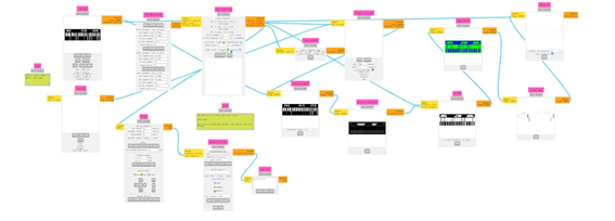
We will start by generating the necessary electronic diagram with the components that we were able to obtain for this assignment, for this first time we will use the PROTEUS software that allows us to generate the electronic design and also the PCB which we treat with the Mods software as we did previously to generate the G code and perform routing with the MonoFab.

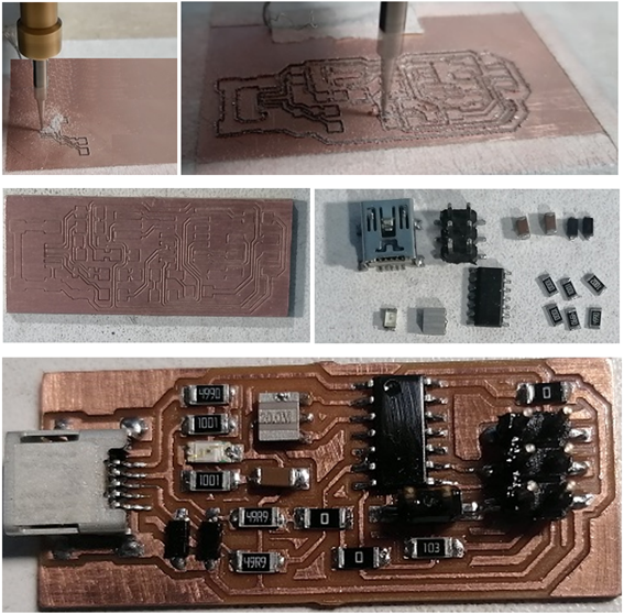
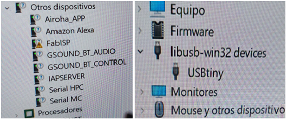
Once we finish soldering the components and clean the board, we connect it to the computer but it does not recognize it immediately so we look for the corresponding Drivers, which in this case would be the one from adafruit (https://learn.adafruit.com/usbtinyisp/drivers ) that after installing it is already recognized by our programmer.
To check its operation we will program a basic example in Arduino with our programmer. We open an example of the IDE and select the board "Arduino Uno", as programmer "USBtinyISP" and upload the program with "upload using the programmer" from the Sketch menu.

Assignment completed everything works fine. . .
created with
Static Site Generator .