5. Electronics Production
# Goal:
Manufacture a milled printed circuit board (PCB) and program it.
# Tasks:
1- Manufacture a PCB called FabTinyISP using a Roland SRM-20 CNC machine.
2- Soldering the circuit parts to the FabTinyISP.
3- Program the FabTinyISP.
# Procedures:
In the pre-fab academy workshop, the engineer introduced us to PCB or the Printed Circuit Board. PCB is the formal name for the basic board, which indicates the layout data, including the number of components. This board is utilized to connect the electronic components by the conductive traces. Also, he supervised us during the PCB fabrication, soldering, and programming process. This week, we used the CNC machine to examine the design rules.
a. Fabrication:
To start the fabrication process, I downloaded the board outline and the traces for FabTinyISP in PNG format from this link.

To change the format of the images, which are PNG, to Ronald mill (.rml) to allow the CNC machine to understand it, I used Fab Modules. Then, I specified PCB traces (1/64) for the traces image and PCB outline (1/32) for the outline image. Then, I selected SRM-20 as the name of the machine. Please be aware that all zero points of the axis X, Y, and Z are at zero before the last step, which is calculation. For the traces, I adjusted the cut depth to 0.1 mm and the tool diameter to 0.4 mm. For the frame, I adjusted the thickness to 1.7 mm and the tool diameter to 0.79 mm. This will produce the routes of the machine movement to produce the final board.

Moving to the Renold SMR-20 CNC machine. I started with placing an FR1-MDF board inside the machine and ensuring it was flat using the screws.
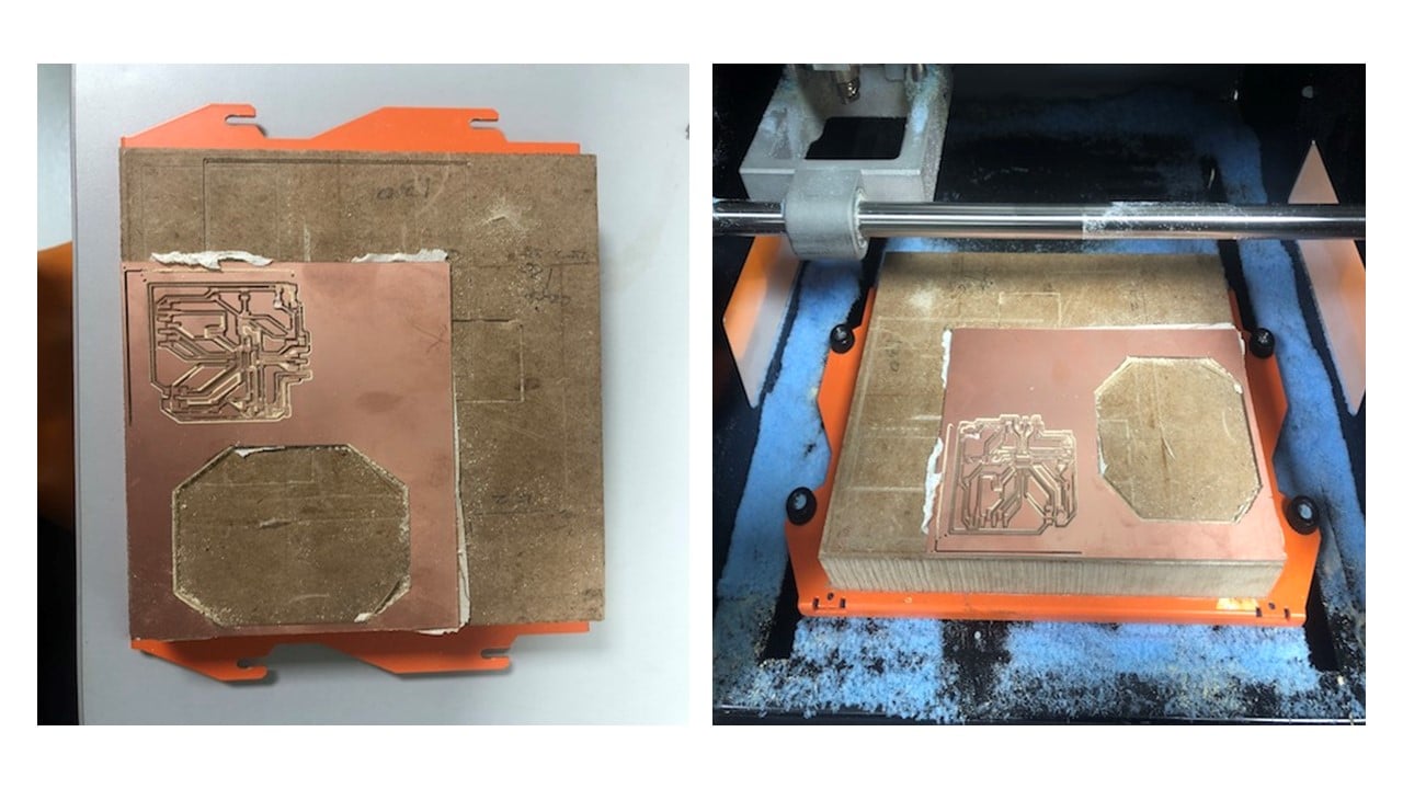
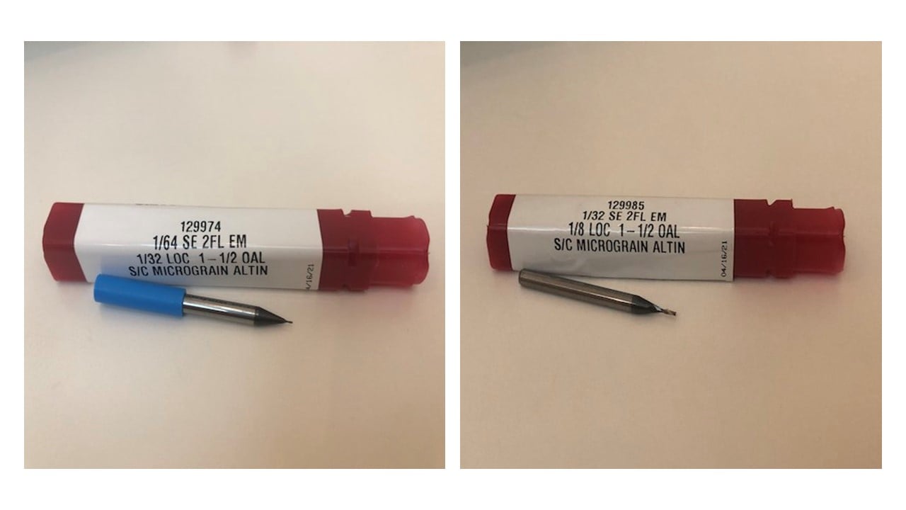
Before milling, I changed the milling bit of the machine using a screwdriver to 1/64 milling bit for the traces and 1/32 for the outline. Then, I selected the origin point (X, Y, Z) based on the available space on the board. After that, I clicked on the cut button and added the Ronald mill (.rml) files to start milling.
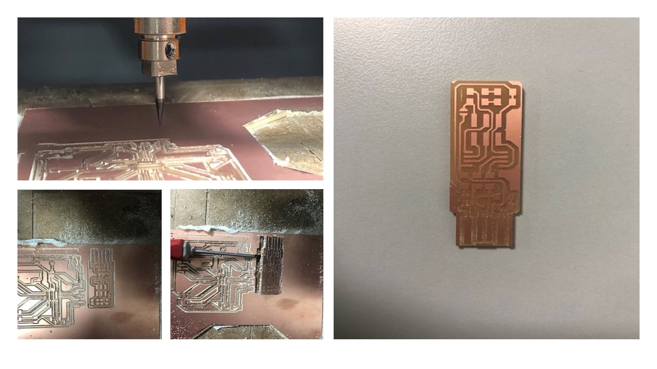
This is the final result is shown below.
b. Soldering:
First of all, I collected the 13 components of the circuit. I used double-sided tape to stick the components on paper to avoid losing them since they are tiny. The table below shows the required components.
| Component | Quantity |
|---|---|
| ATtiny45 | 1 |
| 1kΩ Resistors | 2 |
| 499Ω Resistors | 2 |
| 49Ω Resistors | 2 |
| 3.3v Zener diodes | 2 |
| Red LED | 1 |
| Green LED | 1 |
| 100nF Capacitor | 1 |
| 2x3 pin header | 1 |
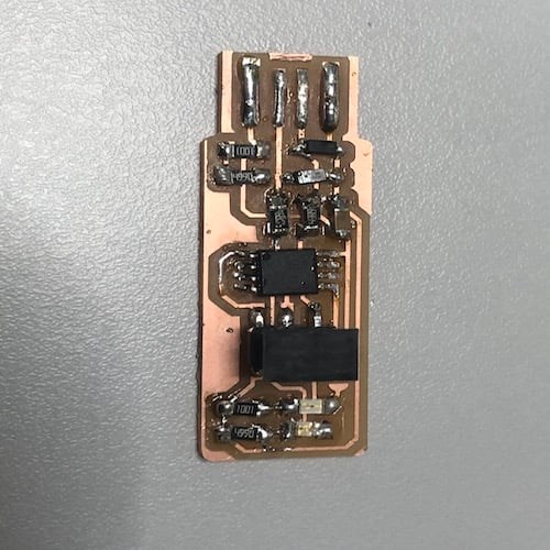
I started the soldering process by adding solder to PCB pads with one hand and try to move the circuit components by the other. I Kept repeating this process for all the components. To avoid having a short circuit, I removed the excess solder and the copper on the edge with a scalpel. Also, I checked the ends of the components using a multimeter.
c. Programming:
Before starting the programming section, I installed CrossPack and Homebrew on my Mac. Then, I typed the following five commands in Terminal and waited for each one to terminate before typing the next:
-[ $ brew tap osx-cross/avr]
-[ $ brew install binutills]
-[ $ brew install gcc]
-[ $ brew tap osx-cross/avr && brew install avr-gcc]
-[ $ brew install avrdude]
I restarted Terminal and typed the following command to confirm that the software version matches my MacOS system [ $ avr-gcc --version]. Then, I checked if the command [ $ make -v] is working.

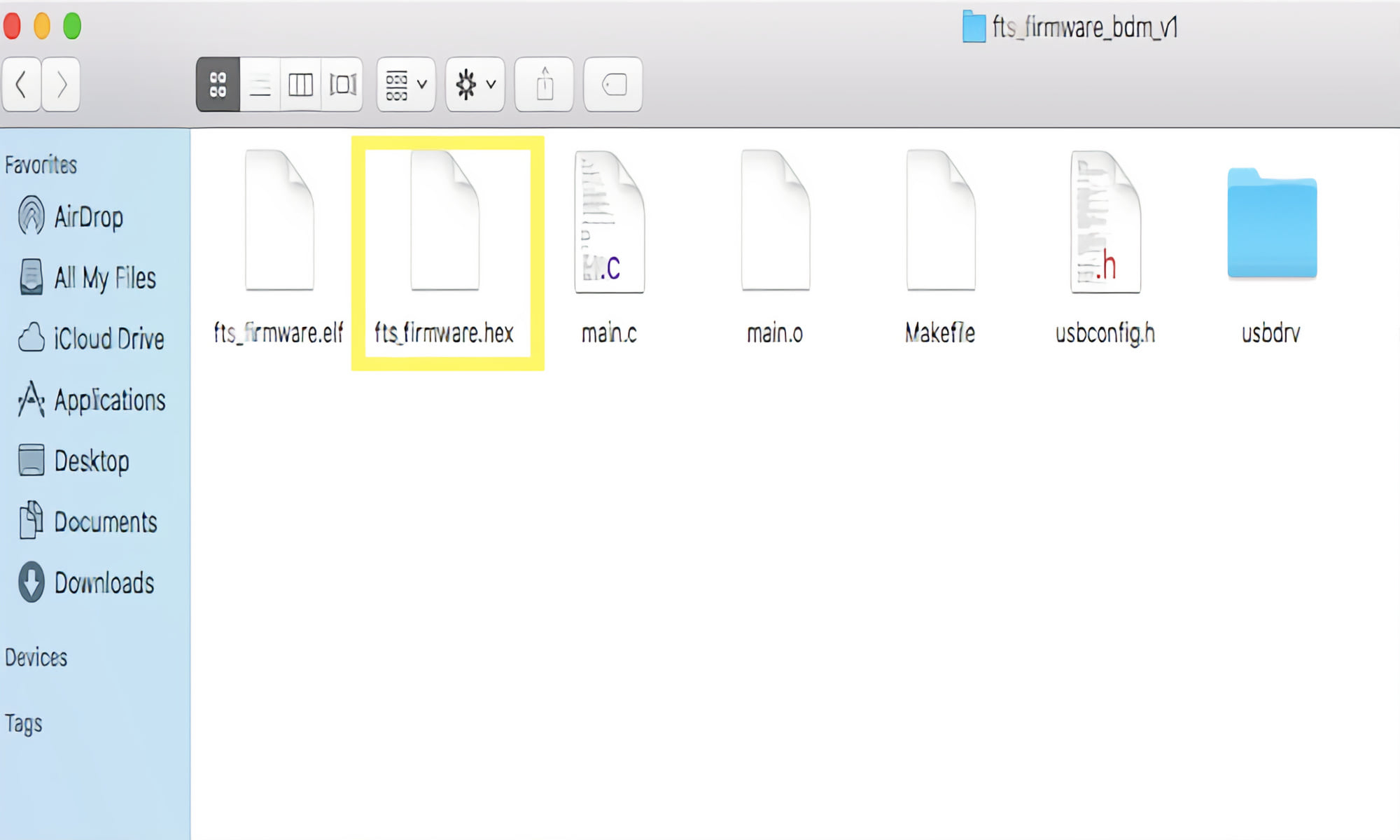
After that, I uploaded the firmware source code from here as a folder named "fts_firmware_bdm_v1". Then, I opened the folder using Terminal and [ $ cd ] command. Then, I run the command [ $ make ] to create a hex file with the name "fts_firmware.hex" that will be used to program the ATtiny45.
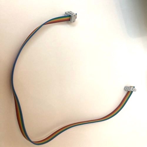
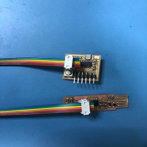
Before programming the FabTinyISP, I fixed two 2x3 connectors at the ends of a ribbon cable using a hammer. Please notice that the order of the colors on both ends must be the same.
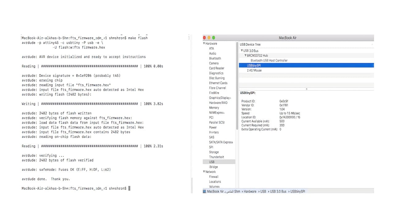
To program my FabISP, I connected it to a previously programed ISP by the ribbon cable. Then, I used Terminal to run the command [$ make flash] to program the flash memory. After that, I checked if the laptop identifies it by clicking on "About this Mac", then "System Report", then "USB".
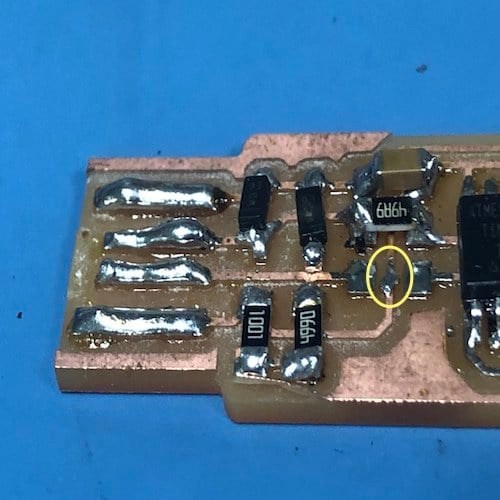
In my first trial, my laptop did not recognize the ISP due to a short circuit in one of the resisters (R4), as shown below.
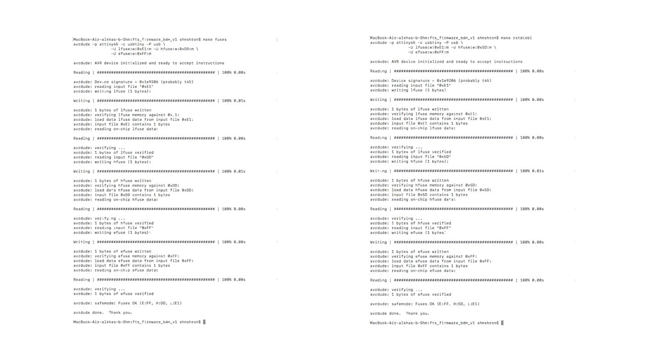
Then, I run the commands [$ make fuses] then [$ make rstdisbl].
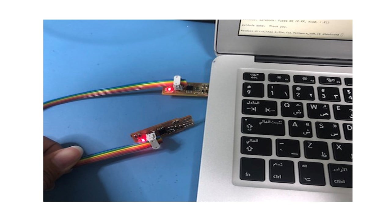
As an attempt to use my FabTinyISP, I downloaded Arduino IDE from this website and connected it to the ISP using the ribbon connecter as shown below.
To add support to the ATtiny, I followed step 3 from this website.

Then, I clicked on Tools and change "Board", "Processor", and "Clock" as shown below. After that, I selected the programmer by clicking on Sketch then "Upload using programmer".

Group Assignment
The link of the group assignment page is here.
# Goal:
Describe the design rules using the Roland SRM-20 CNC machine CNC machine.
# Tasks:
1- Change the format of the traces images to Ronald mill (.rml)
2- Milling in climb and conventional directions at a specific tool diameter.
# Procedures:
To start the fabrication process, I downloaded the interior and the traces in PNG format from this link.
To change the PNG images to Ronald mill (.rml), I mainly used this website. I started by right-click then I selected "Program", "Open server program", and "Roland mill SRM-20 PCB png".

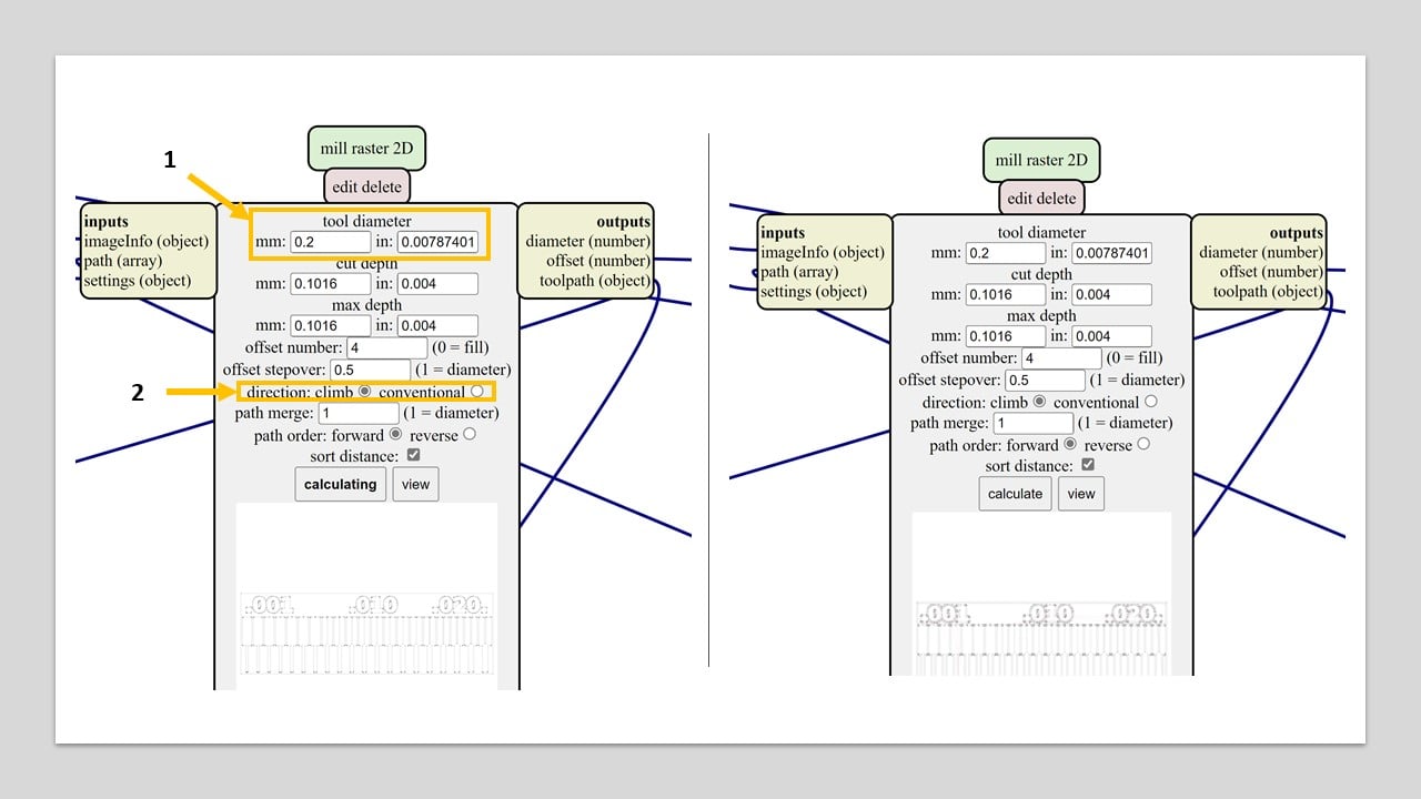
After that, I selected the traces png file and changed the tool diameter to 0.2 mm which equals , which equals 0.00787401 inches.

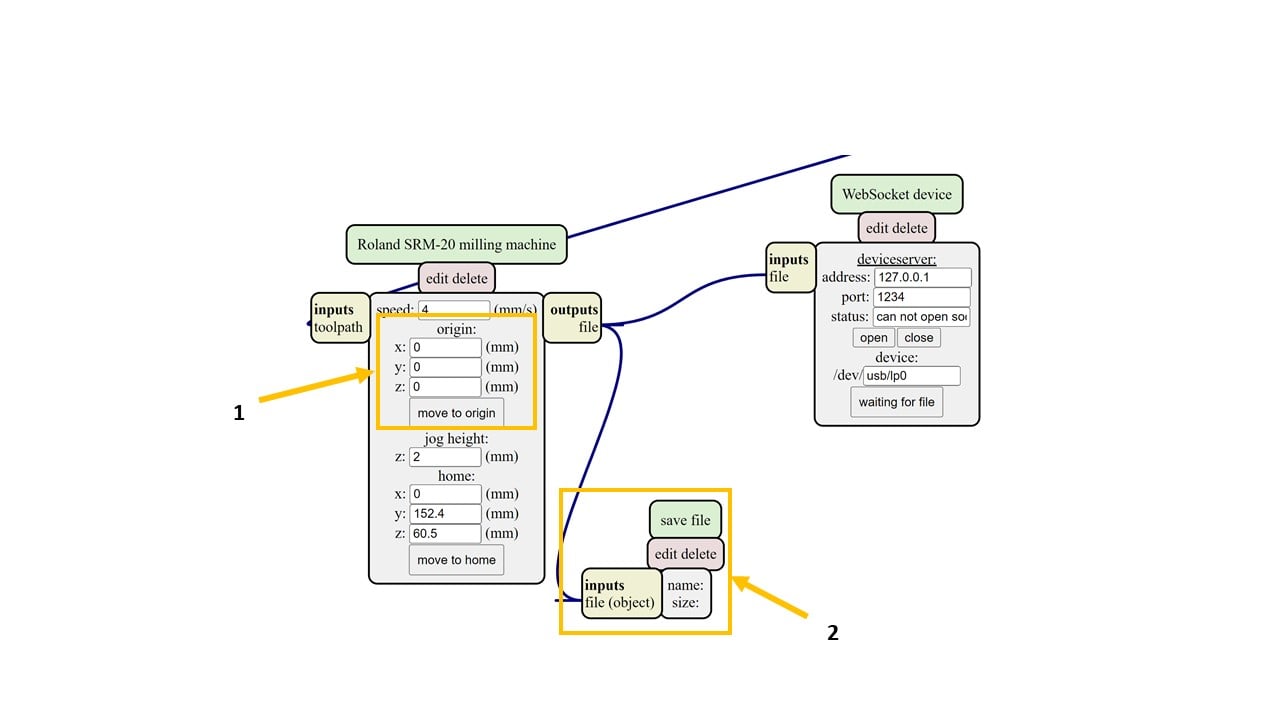
I changed the origin of the machine to zero on all axis. To save the output file, I right-clicked on the page and selected "Modules" and "Open server module" and "file save". Then, I connected the input and output as shown below.
Moving to the mill raster 2D, I changed the tool diameter to 0.2 mm and the direction to climb. Then, I pressed on calculate and saved the (.rml) file. I repeated this step in the conventional direction. Then, I changed the png file to the interior and repeated this step in the two directions.
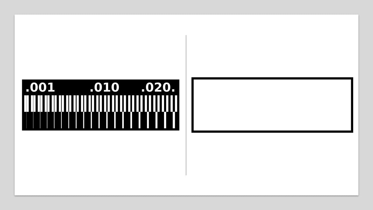
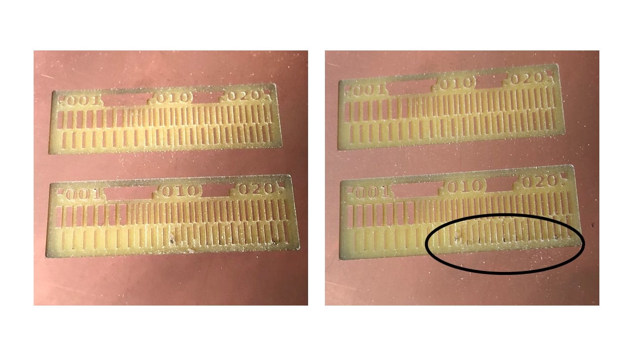
I changed the milling bit of the machine to 1/64 milling bit and selected the origin point. Then, I cut the climb files first then the conventional files. The results are shown below (top is the climb direction). According to the following image, the climb direction milling is clearer compared to the other one.
# Challenges:
I did face two main challenges. The first was during soldering, where I could not easily place the components and solder them, so I kept repeating this process. The second challenge was during the programming process, I kept following the steps given to me, but my laptop was continuously crashing, so I used my sister's laptop.
# Files:
1- Climb Traces
2- Climb Interior
3- Conventional Traces
4- Conventional Interior