3. Computer-aided Design
# Goal:
Learn briefly about two and three-dimensional designing using various softwares.
# Tasks:
1- Learn about 2D designs, i.e. raster and vector graph. Then, design four logos using various software.
2- Learn about 3D designs and use tools, such as rendering, simulation, and animation.
3- Learn about image and video editing.
# Procedures:
This week is a self-taught one, where we should experiment with as many designing softwares as we can. However, engineer Hashem in the pre-Fabacademcy course gave us a short introduction to computer-aided design using Fusion 360. This brief introduction provided us with the main tools required for 2D designs then 3D ones. Also, the engineer recommended that we watch a recorded workshop about 3D designing The Hope orbiter using Fusion 360.
a. 2D Desings:
Images are divided into two types, which are raster and vector images. Raster images rely on the units making up the digital images and are called Pixels. These small squares are shown in some images when you zoom in. However, vector images are made of connected dots or lines. This provides vector images with more sharp lines and clear details when enlarged, compared to raster images.
1- Raster:
In this part, I designed two different logos using two software. The first logo was designed using GNU Image Manipulation Program "GIMP" by following this tutorial. This software is a powerful raster image editor at zero cost. The second software used was Krita, a professional painting program at zero cost. I inspired the second design from this tutorial.
GIMP
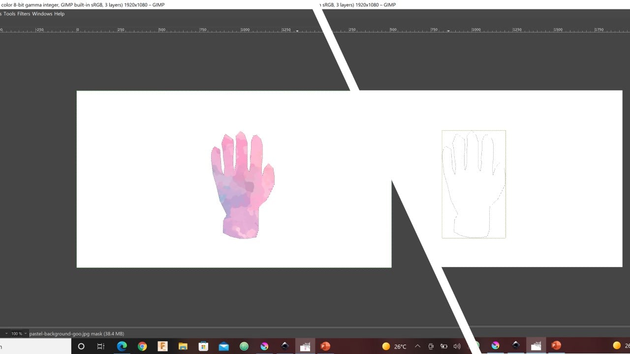
The first logo: I start with googling a glove picture and a pastel background picture. Then, I took an outline of the glove as shown below in black and save it as a new layer. Also, I blur the pastel background picture using filters.

I copied the outline layer and past it on top of the pastel image as a new layer. Then, I created a new white layer and masked the pastel background with a black layer to give it full transparency. I used the Alpha to Selection command to allow the glove outline to appear on the white layer. After that, I fill the black mask of the pastel background with the foreground (FG) color. Thus, the result of the previously mentioned steps is shown below.
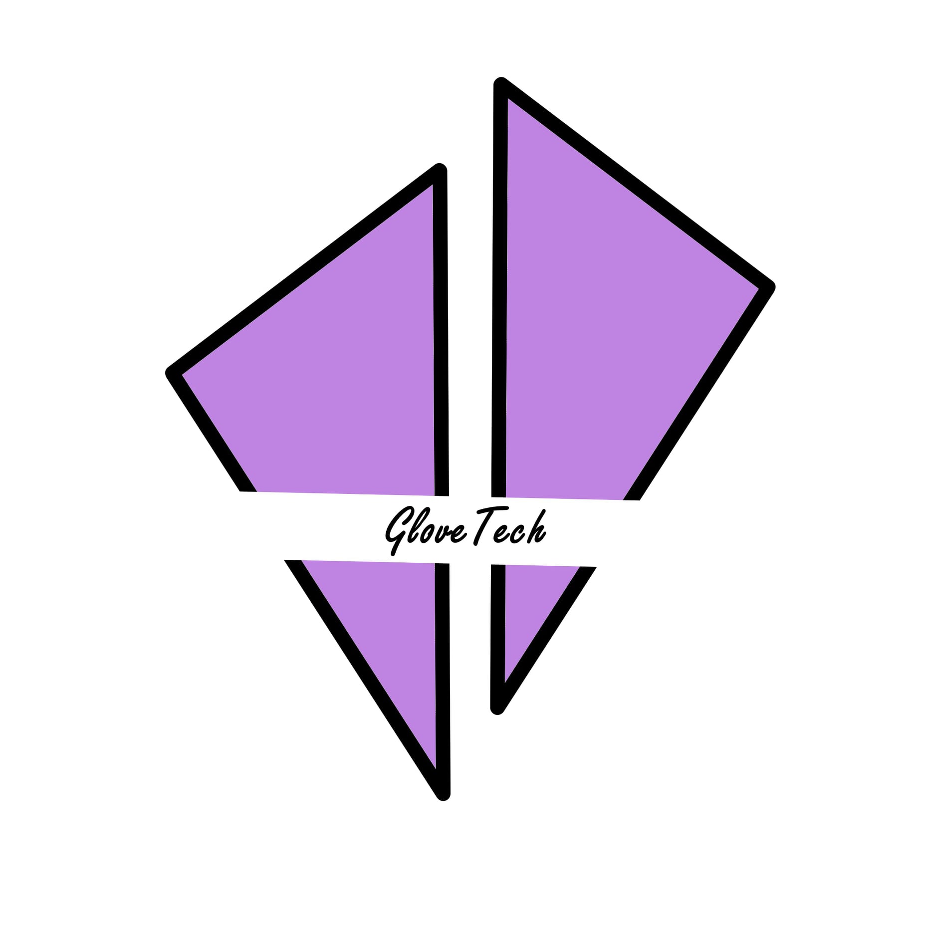
To add more decorations to the logo, I used Splats 01 paintbrush to fill around the glove. Also, I add the name of my final project.

Krita
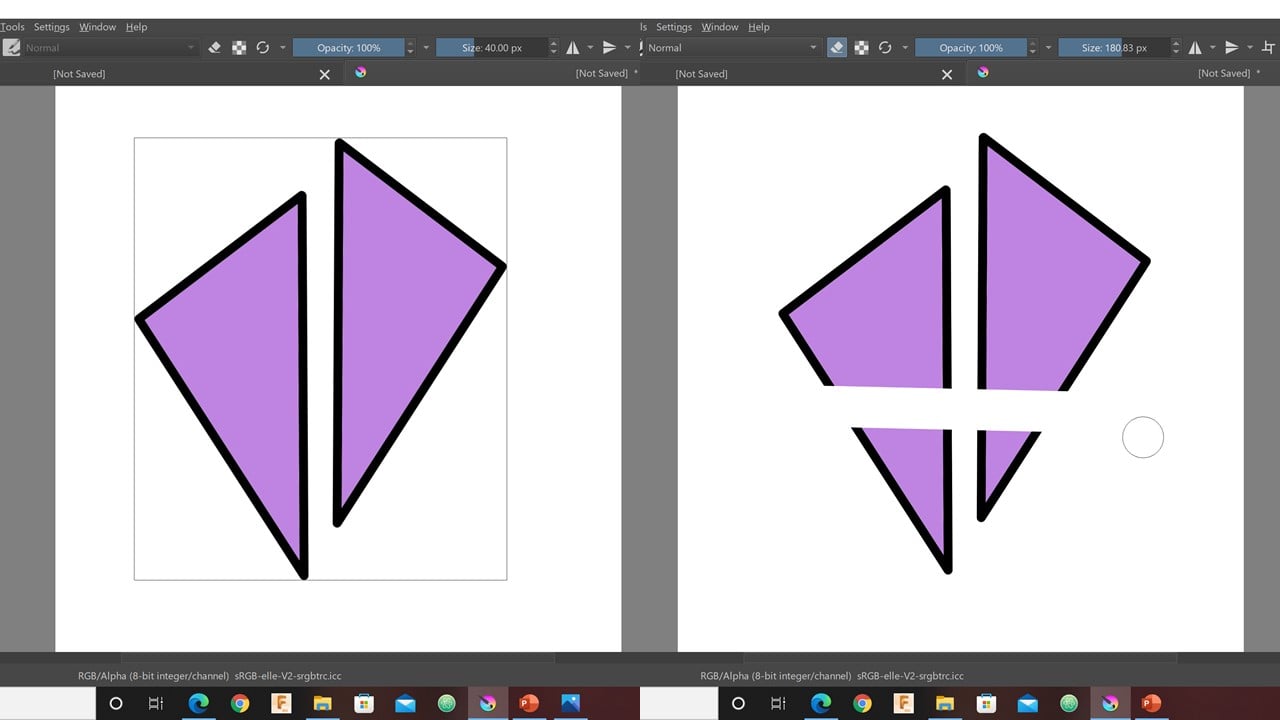
The Second logo: This logo is so simple. I start by drawing a triangle and filling it with color. Then, I create a duplicate of the triangle and use the mirror layer horizontally command to reflect it across the y-axis.

To give the logo an edgy look, I placed the reflection slightly higher than the original shape. Then, I merge the triangles to have one picture and control them easily. After that, I used the eraser to create a space for the project name.
2- Vector:
Here also I designed two different logos using two software. For the first logo, I used Inkscape and repeated the steps in this tutorial. This software is a free advanced vector graphics editor. I used for the second one, a well-known vector graphics editor named CorelDraw. To obtain the second logo, I followed this tutorial.
Inkscape
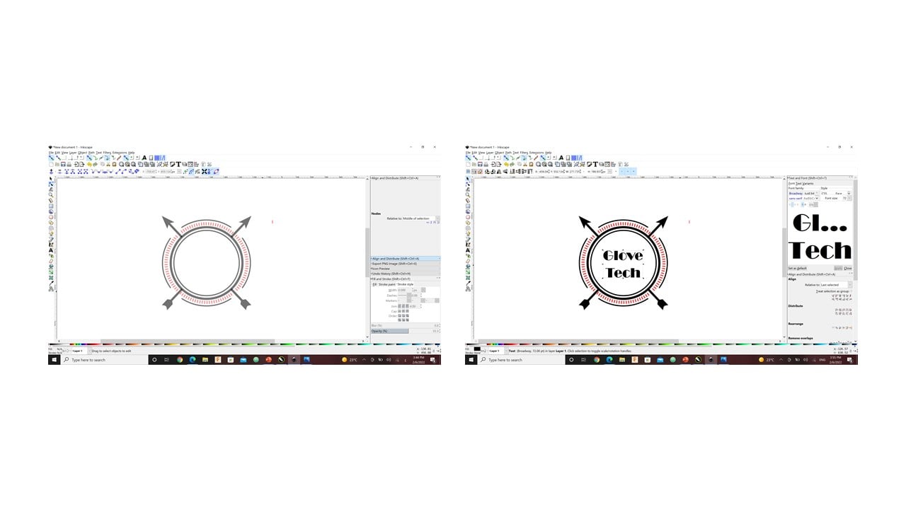
The first logo: In the beginning, I drew a hollow circle with a black outline. Then, I duplicated it and reduced the size of the duplicate slightly. To create an arrow, I started by drawing a small square then rotate it by 90 degrees to have a rhombus. Then, I used the paths by nodes command to move the highest and lowest corners of the rhombus up with the same amount. This produced the tip of the arrow. After that, I drew a rectangle with tiny width and a square to represent the shaft and nock of the arrow, respectively.

After grouping the parts of the arrow, I press the "center on vertical axis" command to ensure that the arrow is in the center of the circle. Then, I rotated the arrow by around 60 degrees and duplicate it. After that, I flipped the duplicate horizontally. Then, I duplicate the largest circle and click on the difference command to remove the arrow parts inside the circles.

Now, I duplicated the small circle and scaled it up to be larger than the large circle. Then, I created a pink square and rotated it to be a rhombus. After that, I click on the "center to horizontal axis" command. I duplicated the rhombus three times so that each rhombus intersects with a quarter of the circle.
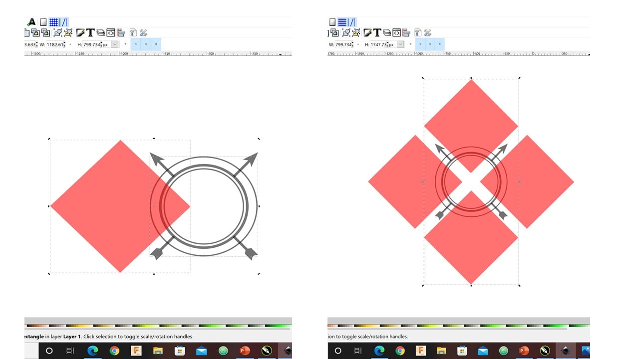
The "intersect" command produced the shape in the left of the image below. Then, again I duplicated the large circle without an outline. Also, I changed its color to pink and scaled it up.

Moreover, I used the "pattern along path" command to repeat a rectangular shape. Finally, I added the project title.
CorelDraw
The Second logo: In the beginning, I drew a polygon. Then, I increased the number of its sides to 6 to get a hexagon and drew three lines connecting the corners. After that, I drew three intersecting circles and removed the drawn lines inside the hexagon.
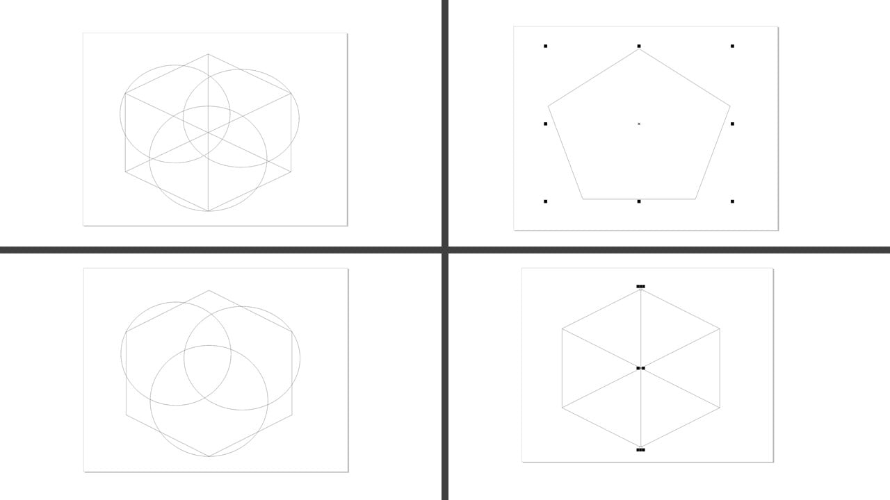
I used the fillet tool to smooth the corners of the hexagon. Then, I deleted two lines inside the hexagon to create a new segment.
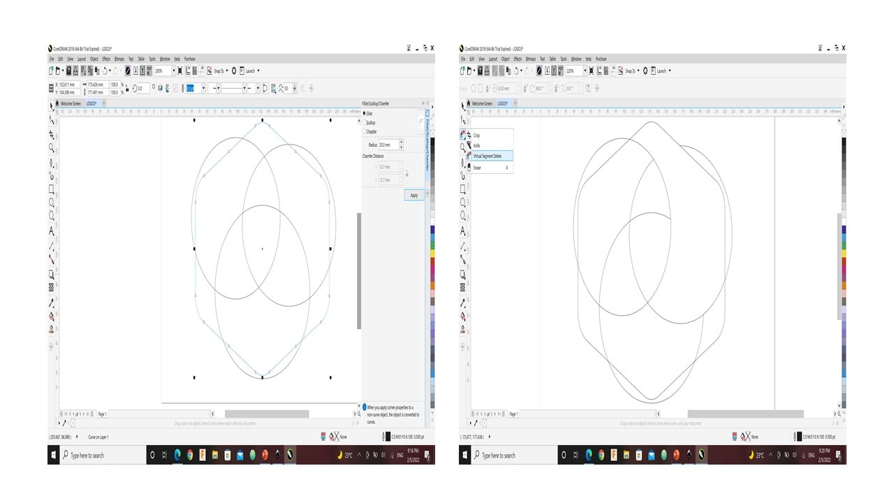
I colored the new segment and detached it from the hexagon. Then, I used the "interactive fill tool" to fill the segment with different shades. After that, I drew a line passing through a segment corner. This line was intersecting with a side of the segment at a point. Then, I drew another segment covering that area. I colored it with the "smart filling tool" and removed all the shapes except the first segment.
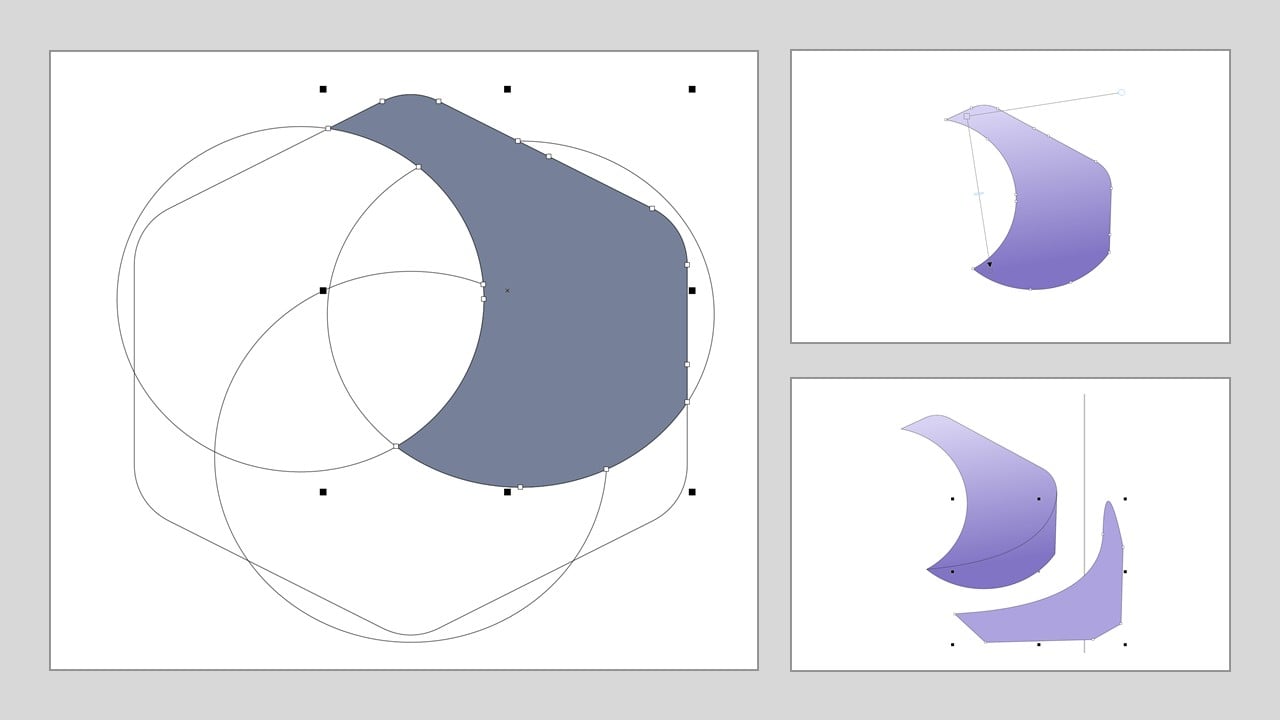
I duplicated the segment and rotated the duplicate by 130 degrees. Then, I attached the segments and added a title.

b. 3D Desings:
The 3D design is the approach of using design software to form an object within a three-dimensional space. We are interested in three main tools, which are rendering, simulation, and animation.
1- Render:
3D rendering refers to applying light to a 3D design to give it a realistic look. In this part, I tried to model two different objects using two software. The first model was designed using Fusion 360 by following engineer Hashem instructions to create a cup. This software is free for teachers and students and, its goal is to design and model assemblies. The second software used was Blender, a software mainly used for animation, art, visual effects at zero cost. The second design from this tutorial.
Fusion 360
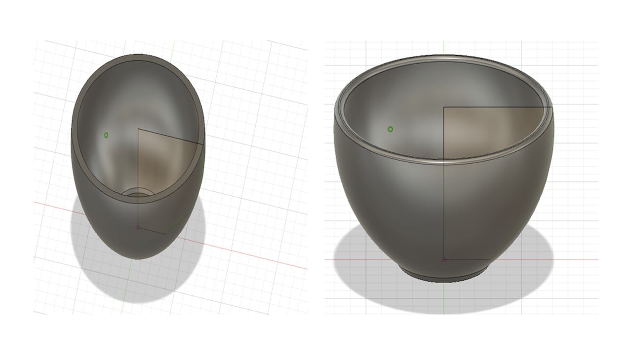
The first design: In the beginning, I drew a cross-sectional of a quarter of the cup. The following image shows the details of the cross-section. Then, I clicked on Create, then Revolve. To get the 3D design, I selected the cross-section as the profile and the z-axis as the revolving axis.

To create a hollow cavity, I clicked on modify, then shell. I fixed the wall thickness, for example, to 3 mm. After that, I used the fillet feature and fixed it to 1.25 mm to smooth out the edges of the cup.
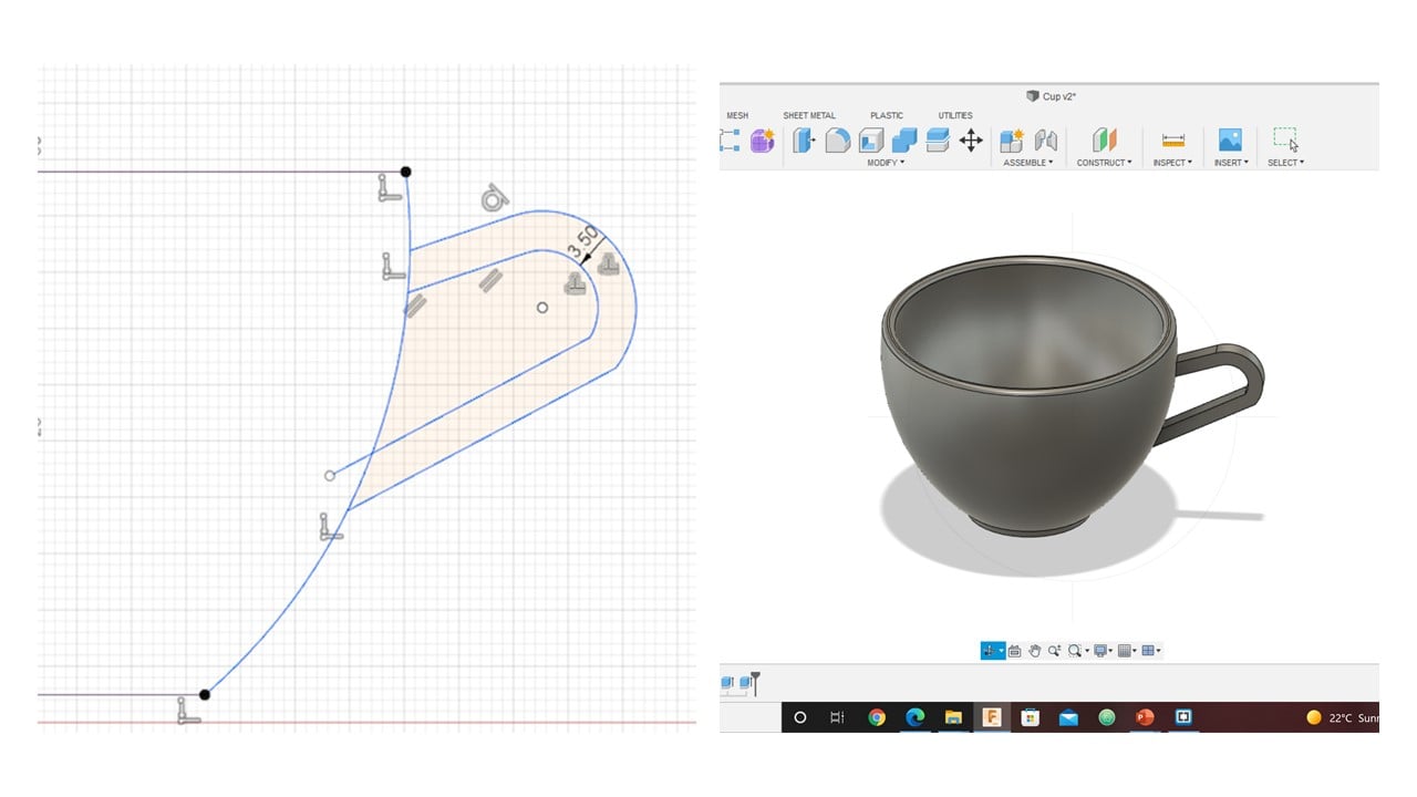
To sketch the cup handle, I clicked on Project/ Include, then project and selected the cup body and drew an arc. Thus, a sketch of the cup body will be produced. Then, I used offset to select the thickness of the handle. After that, I clicked on Extrude, then selected the direction of extrusion to be two and join the handle with the cup body. I fixed the thickness in each direction to be 2 mm.
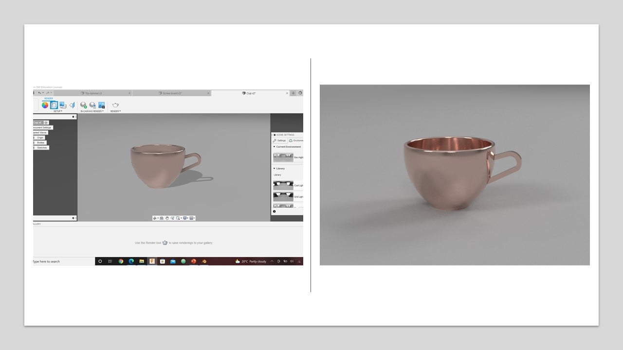
I watched this tutorial to know more about render in Fusion 360. To active this feature in Fusion 360, I clicked on the workspaces button in the top-left of the design window and changed it to Render. In the first trial, I changed the material to Copper and selected the rim highlights as the current environment. Then, I clicked on the in-canvas render button. The result is shown in the left part of the below image.
In the second trial, I changed the material to medium glass in blue shade and fixed the brightness to 1500 and the focal length to 126 mm. Then, I clicked on the in-canvas render button. The result is shown in the left part of the below image.

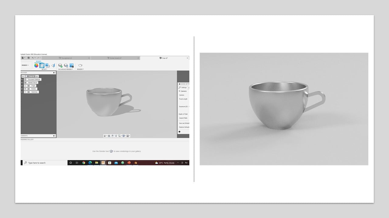
In the third trial, I changed the material to stainless steel and fixed the exposure to 9.2 EV and the focal length to 126 mm. Then, I clicked on the in-canvas render button. The result is shown in the left part of the below image.
Blender
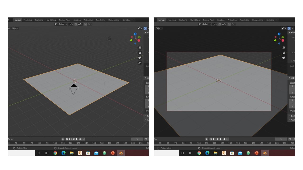
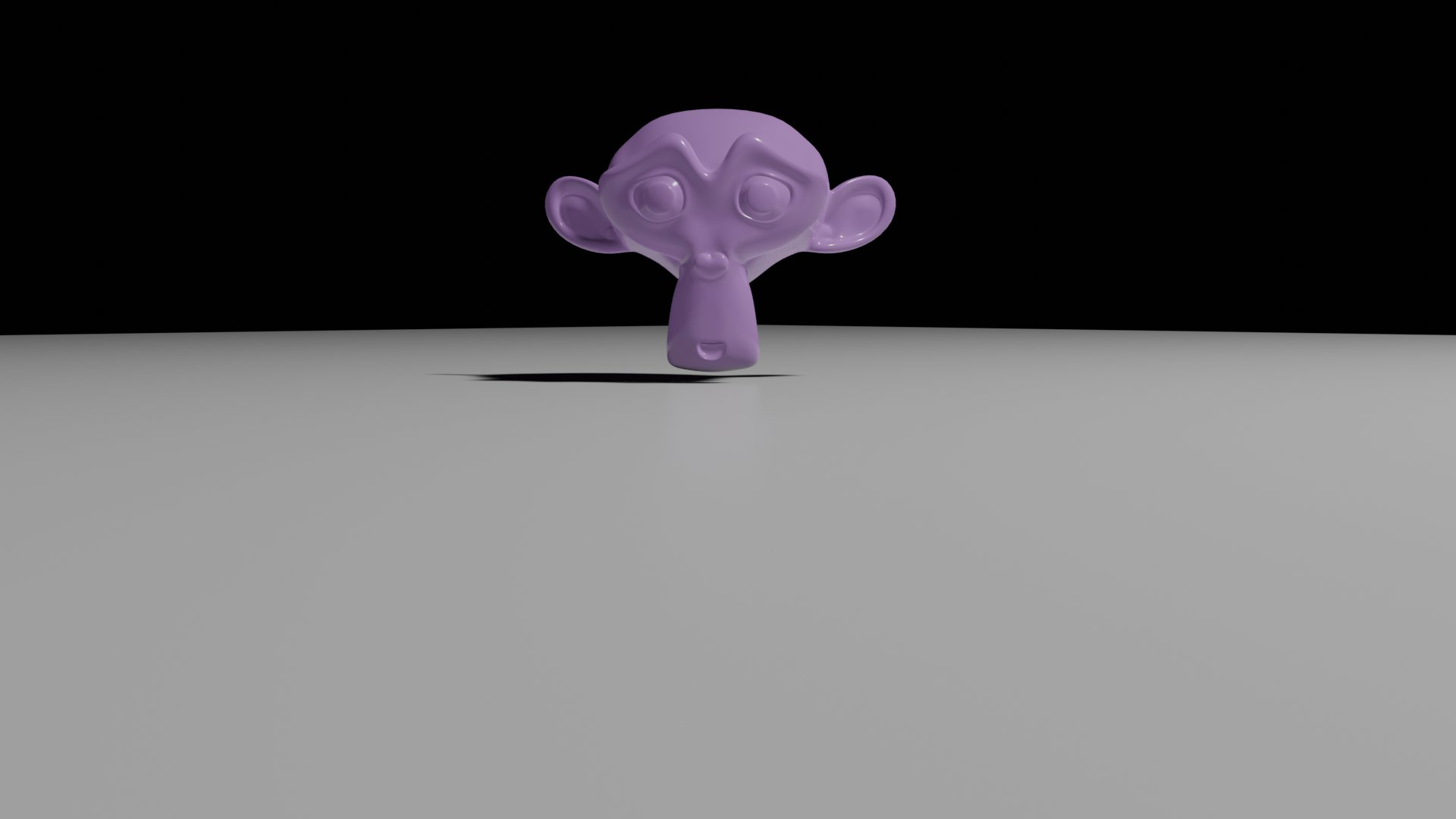
The second design: In the beginning, I deleted the cube and instead added a plane. Then, I scaled up the plane by 5 in the X, Y, and Z-axis. After that, I locked the camera to view and focused it on the plane's origin.
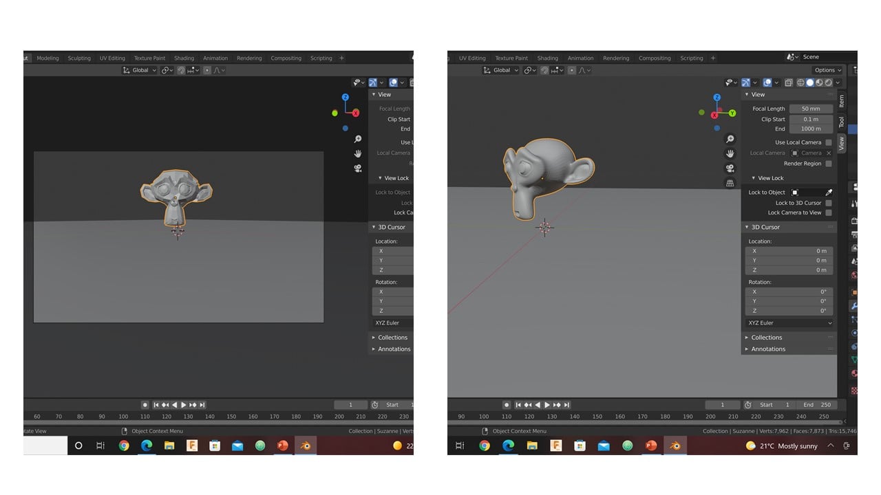
I added a monkey mesh near the origin and rotated it around Z-axis to face the camera. As you can see on the right side of the image, the model is a low poly character so it does not cover many vertices. To increase the number of vertices, I modified the model using the subdivision surface tool. Notice that the model surface became smoother.
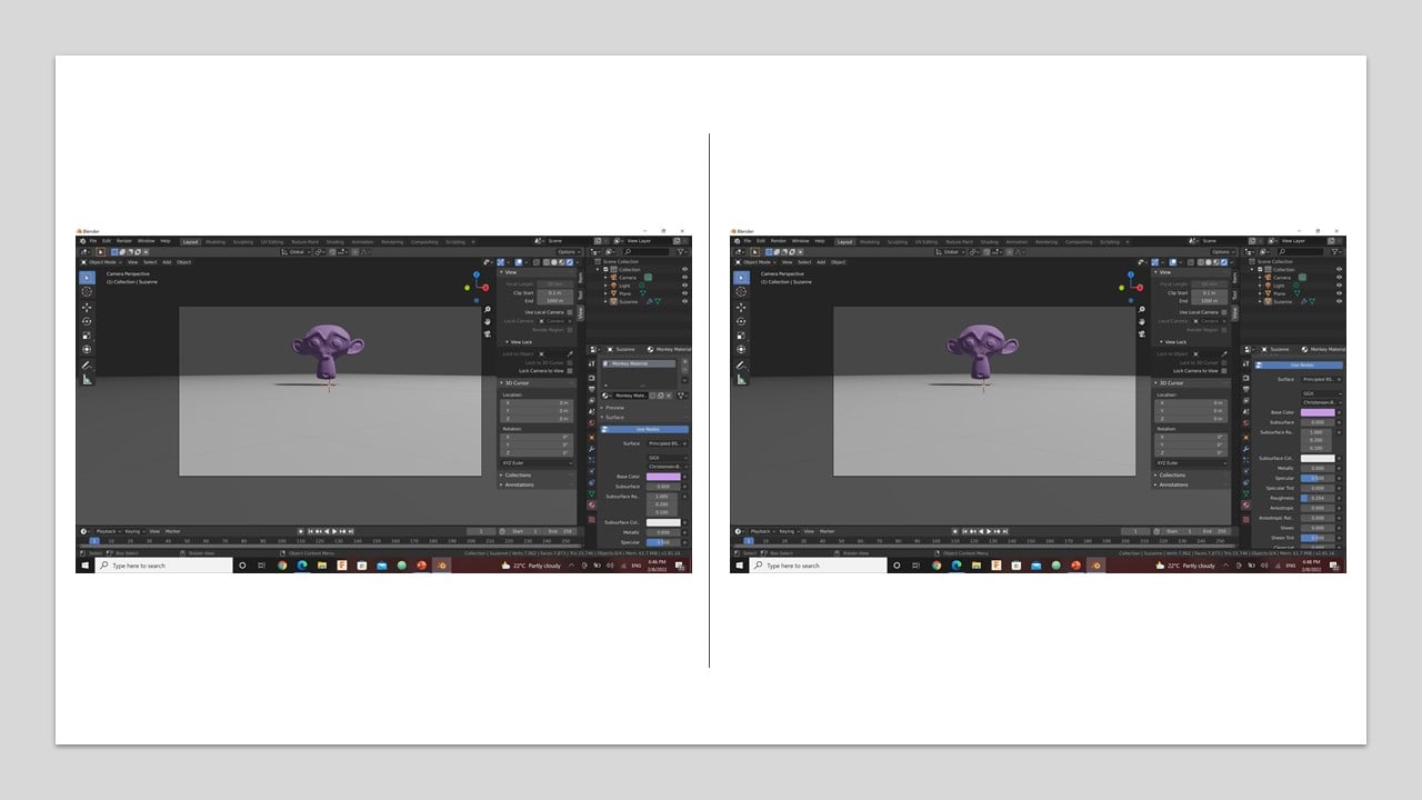
Now, I moved to render the model. I started by changing the material to "Monkey Material". Then, I fixed the material's color to be purple and reduced the material's roughness. This increased the reflectivity of the surface.
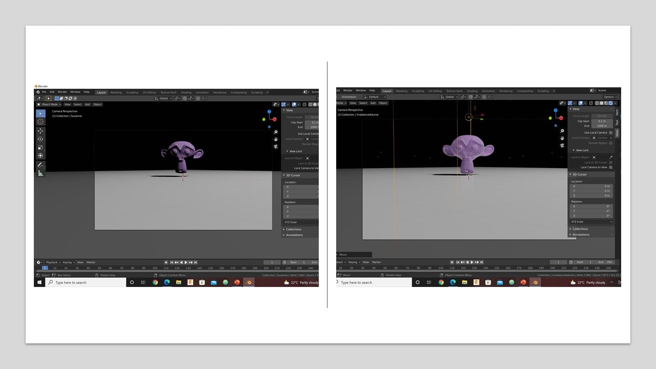
Since I wanted a realistic model, I changed the background by reducing the strength to zero to have the light bulb as the only source of light. Then, I used Eevee render to get the final result.
2- Animation:
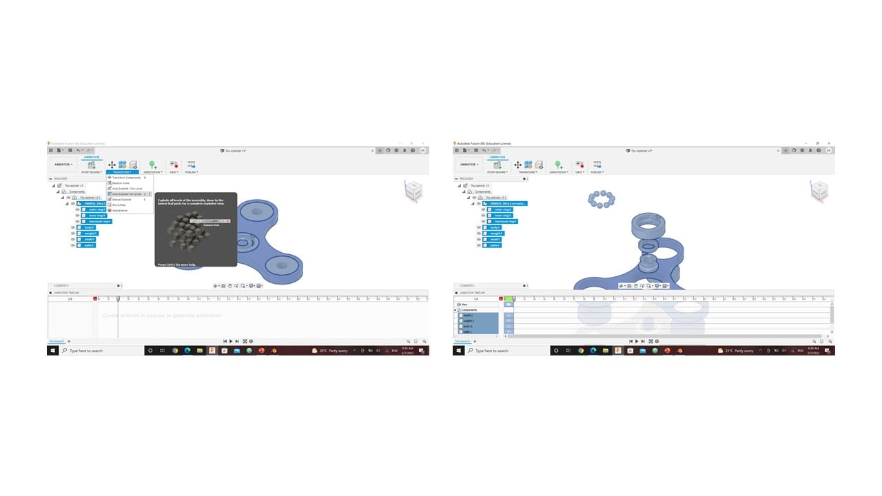
Animation is a technique used to alter and modify figures to seem like moving images. In this part, I tried to model two different objects using two software. The first model was designed using Fusion 360 by following engineer Hashem instructions to create a spinner the animate it using this tutorial. The second software used was Blender, but the software kept crashing.So, only Fusion 360 results are provided.
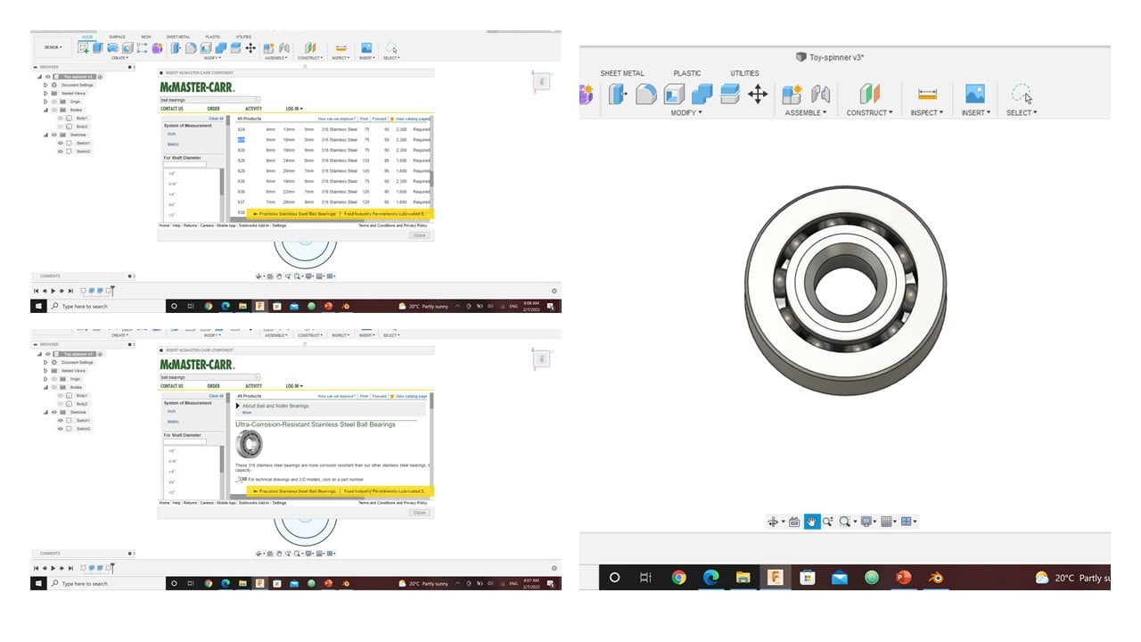
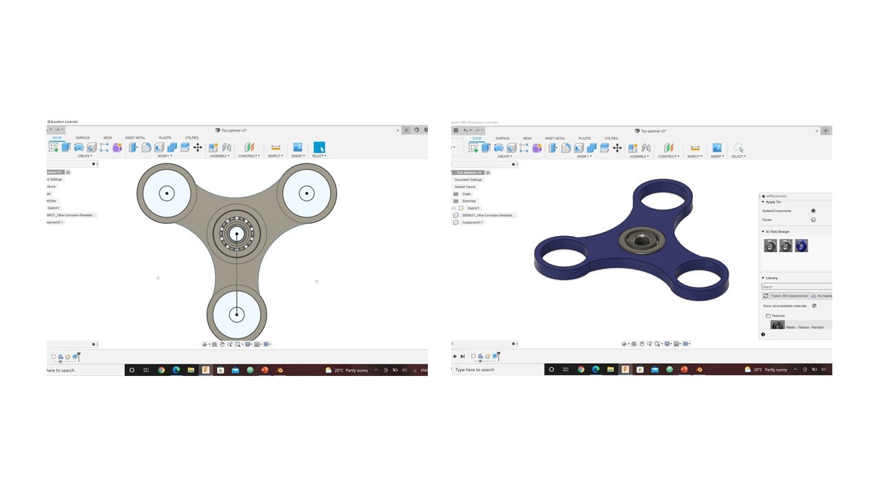
To start, I drew inner and outer circles in the zero point to represent the center bearing with diameters 16 mm and 22 mm, respectively. Then, I used the mirror feature to create a reflection of the circles where the distance between the centers is 27 mm. Instead of mirroring the left two bearings, I use the circular pattern feature by selecting the objects, which are the inner and outer circles, and the center point, which is the zero point. Then, I used the same tool again to create a smallest circle compared to the other two. After that, I connected the center and the outer bearings by drawing 3-point arcs, as shown below

Then, I inserted an Ultra-Corrosion-Resistance ball bearing from the McMaster-Carr with similar dimensions to the design in the last step.
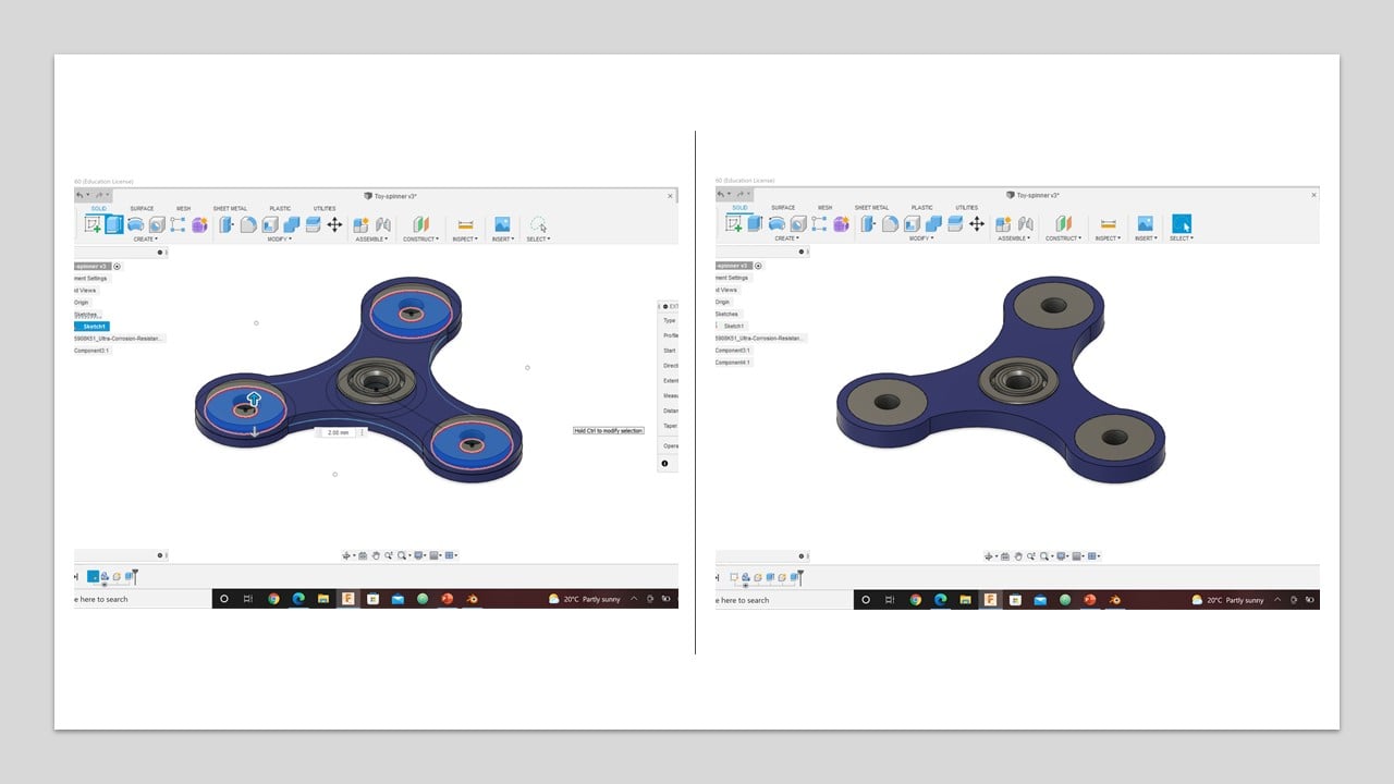
After that, I extruded the spinner body and the outer symmetrically by 2 mm to cover the height of the ball bearing. Then, I modified the spinner's appearance by changing its material to blue plastic. Then, I extruded the middle circles in each side bearing by 2 mm symmetrically.
To active this animation feature in Fusion 360, I clicked on the workspaces button in the top-left of the design window and changed it to Animation. Then, I exploded all levels or parts, reassemble them, and rotated the spinner to create the animation video.
3- Simulation:
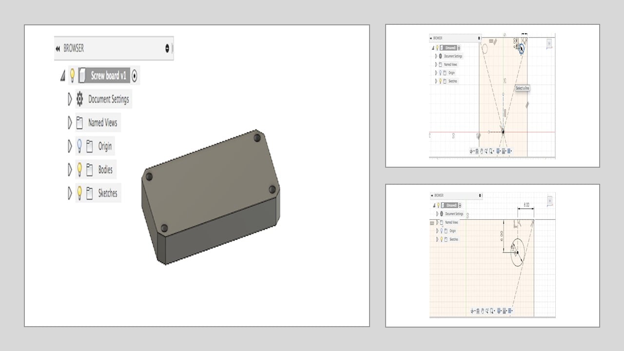
In this part, I designed a screw board using Fusion 360 by following engineer Hashem instructions. Then, I used this tutorial to apply a static simulation.
In the begining, I drew a center rectangle with 50 mm width and 100 mm length starting from the zero point.Then, I drew two perpendicular constriction lines, each is 6 mm in length, at one of the rectangle corners. After that, I drew a circle with 5 mm diameter as shown in the following images. To avoid repeating step 3 for the left corners, I used the mirror feature by selecting the circle as the object and adding two perpendicular construction lines as the mirror lines. Then, I extruded the surface by 10 mm and smoothen out the rough edges using 5 mm chamfer distance.
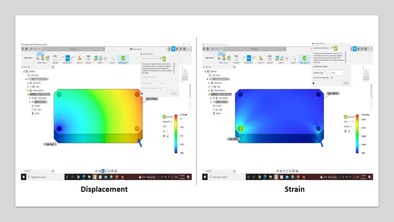
To active this simulation feature in Fusion 360, I clicked on the workspaces button in the top-left of the design window and changed it to Simulation. Then, I chose static stress simulation and the study material as Aluminum 6061.

I fixed the board at a single screw hole. Then, I applied a load horizontally to another screw hole.

Then, the solution of the simulation is shown below. Each graph is an indication of the actual reaction of the board if I applied the same load in real life. The graphs are representing deformation, stress, displacement, and strain.

c. Image and Video Editing:
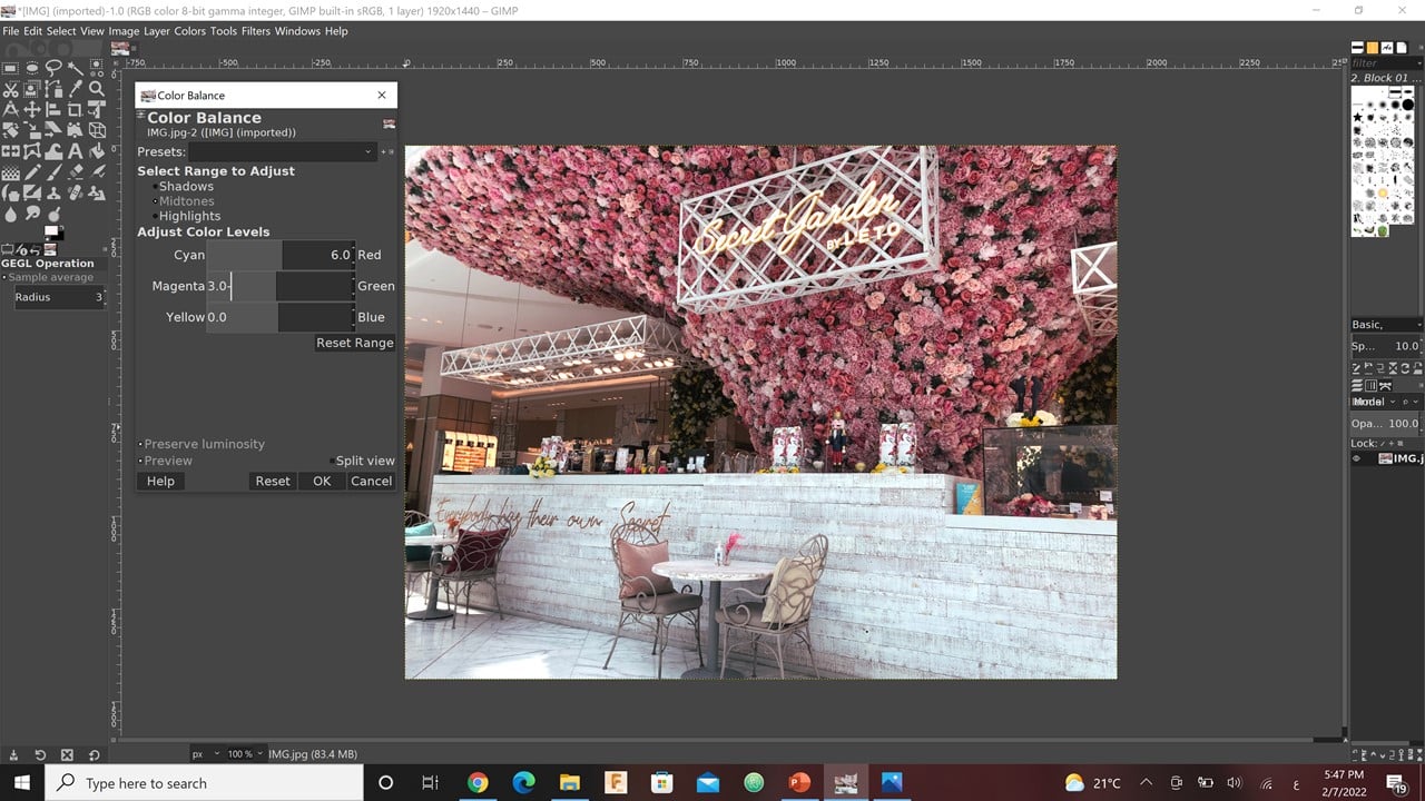
In this part, I edited an image I already have on my phone using GIMP. I watch a tutorial on Youtube that describes the main steps to do so. Then, I edited a video download from Youtube by this website, as well, and followed the steps given by this tutorial using kdenlive software. To compress photos and videos, I use mainly Facebook. However, the video I edited is too large. Thus, I cut it to 11 seconds.
1- Image Editing:
I started with scaling down the picture and increasing X and Y resolutions. Then, I moved to edit the "Shadows and Highlights tool". This can cause show the details in the shadow and reduce/increase the details in the highlights. Thus, I modified the shadows to 16 px and the highlights to 19 px. Then, I increased the "White point Adjustment" to 3. This will brighten the whole picture. I altered also the "Color Balance tool", where I fixed the mid-tones red to 6 and magenta to 3.
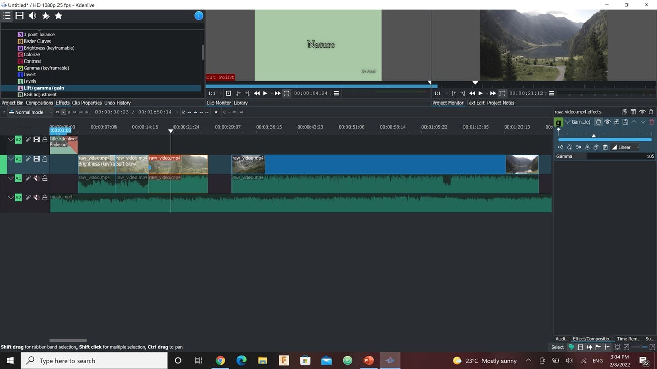
2- Video Editing:
I started with dragging and dropping the music and the downloaded video. Then, I dragged the video to the editing area, where I muted the original video. Also, I tried to adjust the length of the music required to cover the whole edited video. After that, I added a title using "Title Template". In the last step, I trimmed the video into smaller parts and I added "Effects" to each part.
# Challenges:
I did not have any previous experience in using all the softwares except Fusion 360 software. Thus, I took me a long time to get use to each program. Now, I think I know the basics about these software only, so I need to practice to master using them.
# Files:
1- GIMP Logo
2- Krita Logo
3- Inkscape Logo
4- Render Fusion 360
5- Render Blender
6- Animation Fusion 360
7- Simulation Fusion 360
8- Image Editing