4. Computer-Controlled Cutting
# Goal:
Learn about the use of Vinyl cutter and laser cutter.
# Tasks:
1- Laser cut a keychain using Universal Laser System interface.
2- Design a press-fit kit using Fusion 360 software. Then, laser cut it on cardboard with 6 mm thickness.
3- Cut a laptop sticker using Vinyl cutter.
# Procedures:
We had a pre-fab academy workshop, where the engineers gave us an introduction to laser cutting. We designed and cut a keychain made of MDF wood using Fusion 360 software and the Universal Laser System interface, respectively. This week, we implemented the information learned previously to create a cardboard press-fit construction kit. Also, we learned about Vinyl cutters. Then, we made two laptop stickers.
a. Laser Cutting:
Laser cutting is a computer numerical control cutting process where a high-intensity laser is utilized to engrave and cut various materials.
1- Keychain:
In this part, I started by drawing a small circle inside a bigger one using CorelDraw software. Then, I inserted a simple black-and-white design from the internet as a picture in PNG format and wrote my name inside the big circle. After that, I right-click on the uploaded picture and choose "Power Trace" and "Detailed Logo" to achieve a detailed picture.

To delete the background from the detailed picture, I pressed "Enter" on the keyboard. Then, I selected the circles, the picture, and the written name, and I right-click on the red color shown in the color sidebar to change their outer borders to red. This will allow the laser cutter, later on, to cut these borders, while the black color will be engraved.
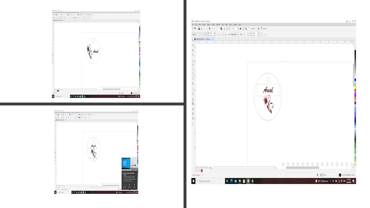
Then, I saved this file to a USB and used the computer next to the Universal Laser System to set the printing setting for the used material " MDF wood ". After the printing process is completed, I allowed the printer to cool down for a few minutes before removing the final piece.

2- Press-fit kit:
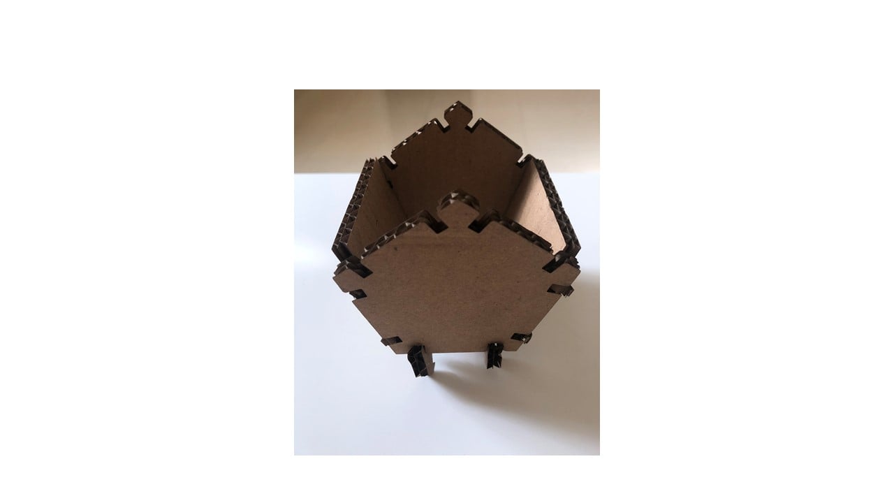
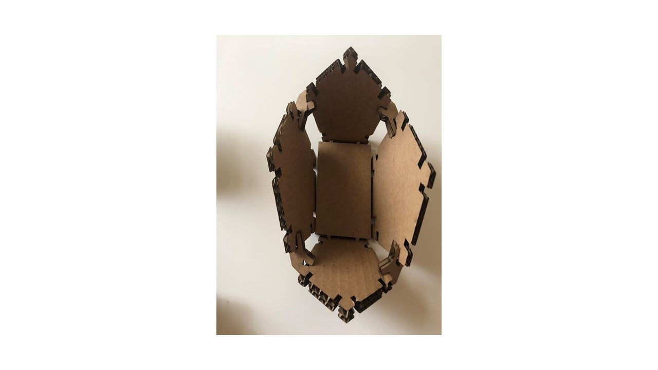
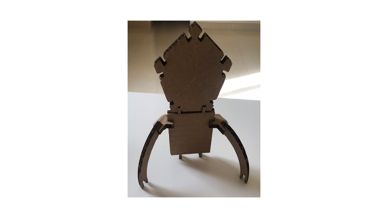
In this part, the goal is to design a press-fit construction kit using Fusion 360 software, and laser cut it in cardboard.My press-fit kit consists of pentagons, chevron arrows, arc shapes and squares. This design was inspired by Matt Blackshaw as shown in the picture below. [website]

Before starting the sketch, I set up eight parameters needed for the design by clicking on Modify, Change Parameters, then the User parameters. Three of these parameters are related to the chevron arrows while the rest to the pentagons.

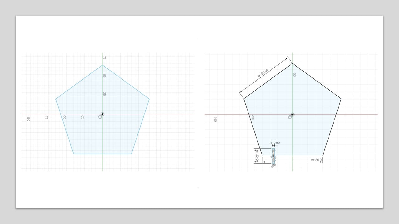
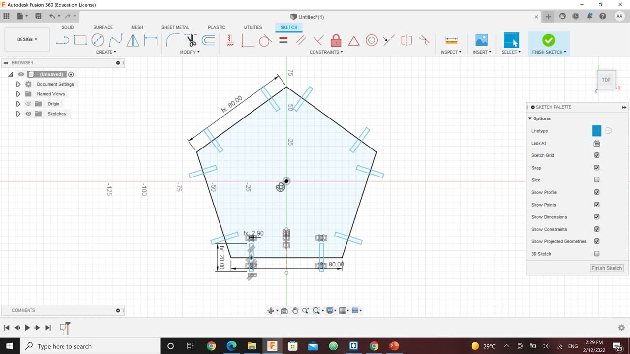
To sketch an equilateral pentagon, I used the " Circumscribed Polygon " tool. Then, I set the length of the pentagon's side to 80 mm. Also, I sketch a rectangle using the "Center Rectangle" tool near one of the corners. Then, I set the length of the rectangle to double the slot parameter, which is 20 mm. While the rectangle's width to thickness minus the kerf, which is 5.833 mm.
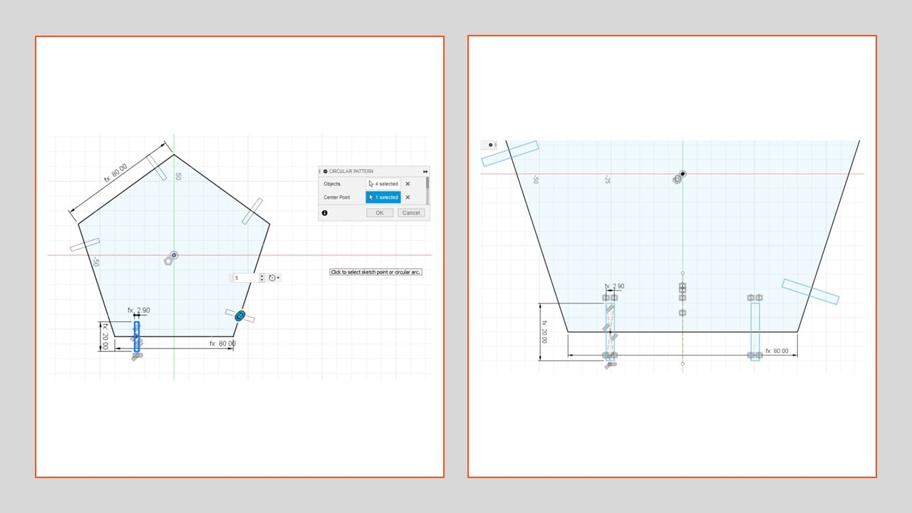
I used the "Circular Pattern" tool to repeat the drawn rectangle five times, one at each side of the pentagon. After that, I mirror the original rectangle on the first side using the "Mirror" tool and a construction line. Then, I used the "Circular Pattern" tool again. Thus, I have two rectangles on each side of the pentagon.
The final step is to extrude the pentagon body, i.e. without the rectangles, by the thickness, which is 6 mm.

Moving to the chevron arrow, I started by drawing two lines with the length "a1" using the "Line" tool. The second line is angled by 45 degrees from the first, which is a horizontal line. Then, I drew two perpendicular lines with length "a3" at the beginning and the end of the previous lines. After that, I drew parallel lines to the first two with the length of "a2". To add the slots, I drew a center rectangle to one side with similar dimensions as the rectangles in the pentagon. Then, I mirror it using the "Mirror" tool and a construction line. To finalize it, I extrude it by 6 mm.

Moving to the arc shape, I drew an arc using the "3-point arc" tool. The length of the arc is 80 mm, which is the side length of the pentagon. Then, I used the "Offset" tool to create another arc away from the original one by 10 mm. Then, I drew a rectangle using the "Center Rectangle" tool at one side of the arc shape. The dimensions of the rectangle are similar to the rectangles drawn in the pentagon.

Then, I tried to adjust the rectangle using the "Move/Copy" tool. After that, I repeated the last two steps on the other side of the arc shape.
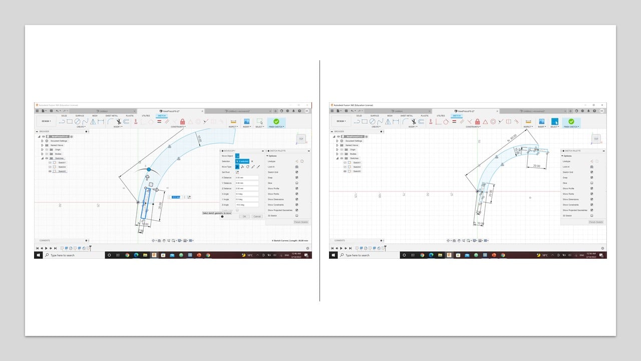
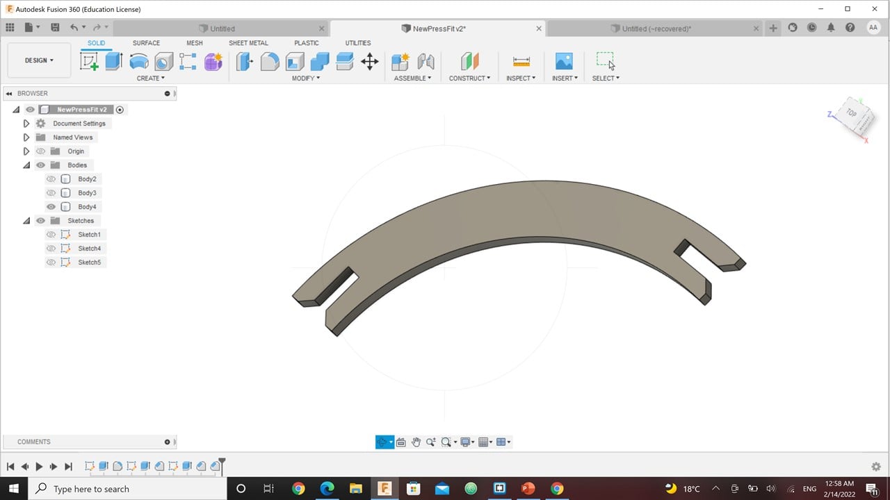
I extruded the sketch to transfer it to a 3D design by 6 mm, which is the thickness.
The final shape is the square. I drew a square using the "Center Rectangle" tool and adjusted the dimensions to be 80 mm. After that, I drew a rectangle again with 5.833 mm width and 20 mm length.

I used the "Mirror" tool to copy the rectangle drawn previously three times. Then, I extruded the shape by 6 mm.

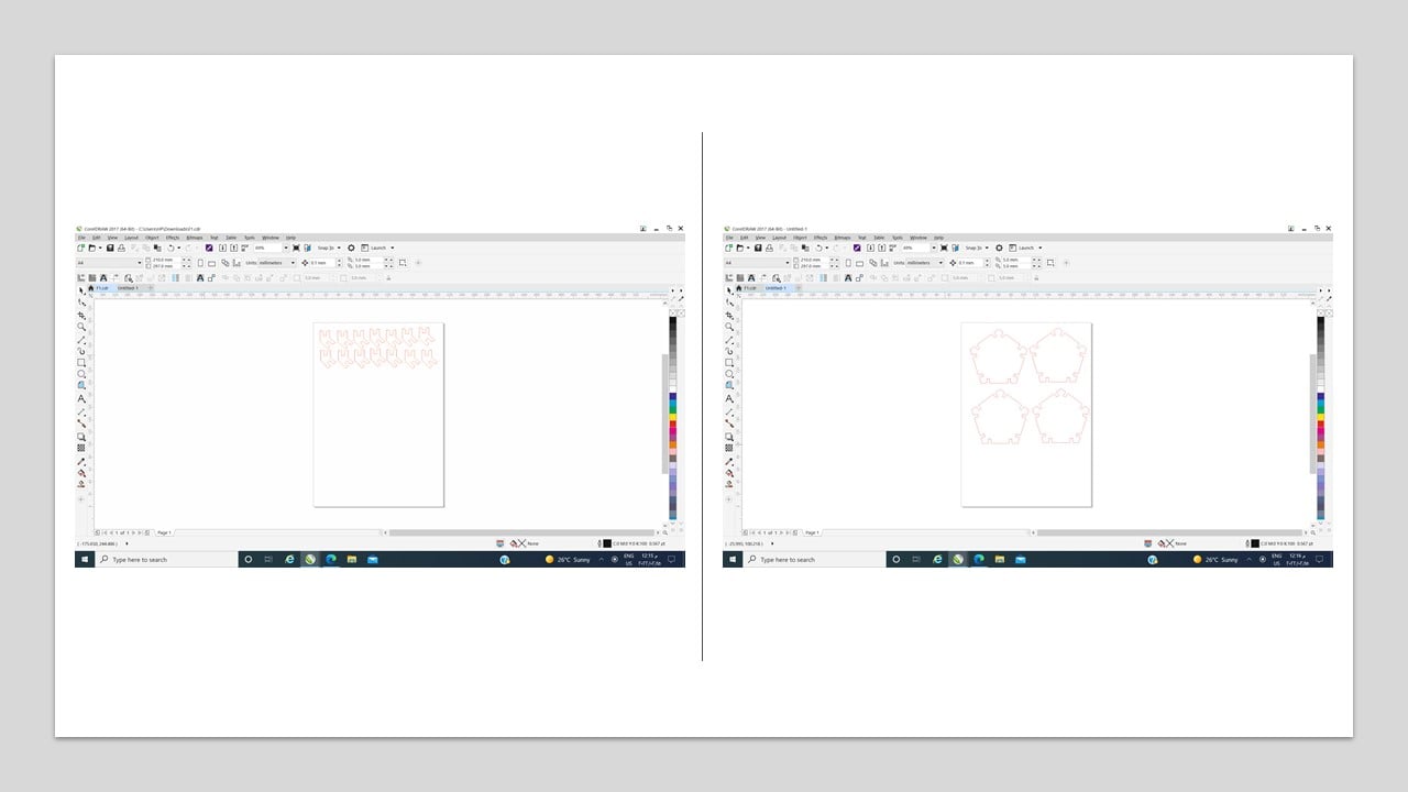
I created four new sketches, where each one has the top face of the previously designed shapes. Then, I saved them as DXF. Also, I used CorelDraw software to arrange the repetitions of each sketch and to outline the sketch in red. Then, I used a 6 mm cardboard and the Universal Laser System interface to laser cut the shapes. The settings are shown in the table below.
| Color | Power | Speed | PPI |
|---|---|---|---|
| Red | 100% | 12% | 500 |

The result from cutting are 6 pentagons, 15 arrows, 3 squares, and 2 arcs.
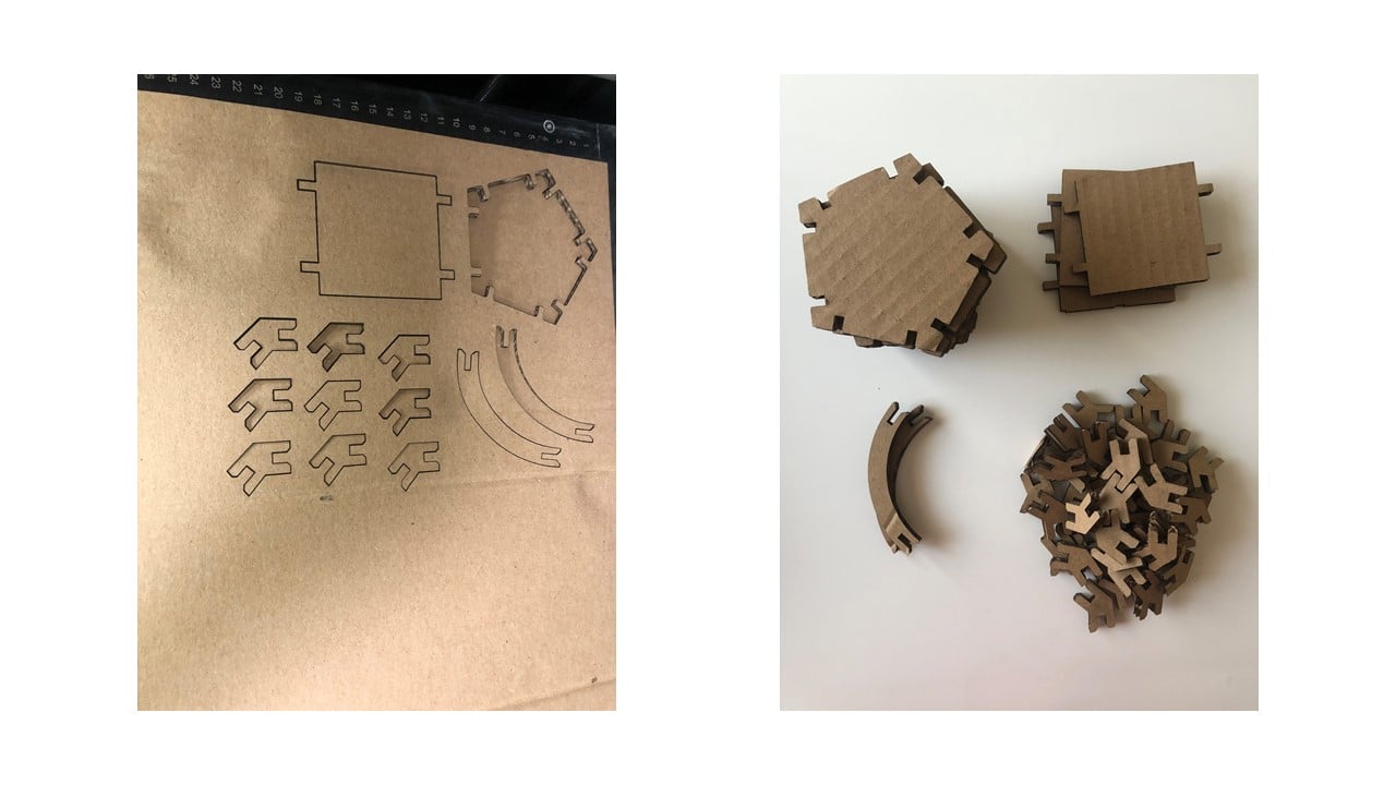
I tried to connect the shapes in different ways to have four press-fits.

b. Vinyl Cutting:
Vinyl cutting is a computer-controlled cutting process. This process contains a small knife or blade that cuts an outline of a vector image in a sheet of vinyl.In this part, I created a laptop sticker using Inkscape software, CorelDraw software, and the Roland Vinyl Cutter CAMM-1 GS-24 machine. This machine is shown below.

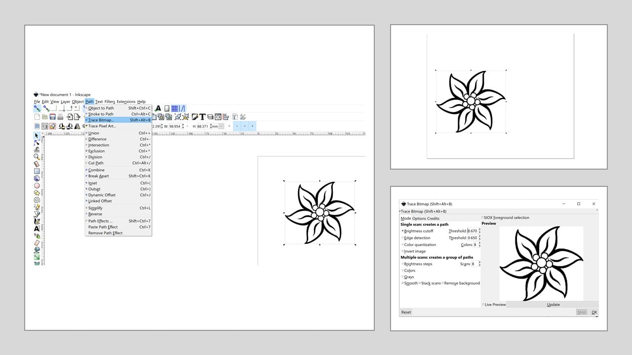
I started by downloading a simple flower picture from the internet. Then, I used Inkscape software to create a path or outline for the picture by pressing on "Path" and "Trace Bitmap". After that, I increased the brightness to increase the outline clarity. Then, I saved the file as a PDF.
I opened the PDF file in CorelDraw software and changed the outline to a hairline. Then, I right-clicked on the red color. After that, I clicked on the "Roland Cutstudio" button to open the Roland Cutstudio software. Then, I adjusted the cutting setup to get the cutting area from the machine. Then, I changed the length to 100 mm.

To start the cutting process, I fixed the origin of the machine and clicked on the "Cutting" Button. After the process is completed, I cut out around my picture. Then, I used a scalpel to remove the unwanted pieces of the vinyl. Then, I coved my sticker with an application tape to place it easily on my laptop.


Group Assignment
The link of the group assignment page is here.
# Goal:
Find the kerf and the proper cutting parameters to specific material.
# Tasks:
1- Draw a simple design using CorelDraw software.
2- Lase cut the design using Universal Laser System interface with various cutting power, speed and pulses per inch (PPI).
3- Draw a rectangle divided into 12 smaller ones to calculate the kerf.
# Procedures:
a. Proper Laser Cutting Parameters:
For this assignment, I choose the material to be cardboard with 6 mm thickness. Also, I draw a square with my initial letter "A" using CorelDraw software. I have tried seven different combinations of speed, power, PPI to get the proper cardboard cutting parameters using the Universal Laser System interface.Please remember that the red color refers to cut, and the black one refers to engraving.
The first trial
The initial guess of the parameters is shown below in the table. This results in light engraving and no cut at all. [Figure 1 in the following image]

| Color | Power | Speed | PPI |
|---|---|---|---|
| Black | 27% | 80% | 500 |
| Red | 30% | 80% | 500 |
The Second trial
Due to the previous trial results, the power for both colors was increased. However, the speed for both of them was kept at 80%. This results in a clear engraving and a slightly deeper cut but not the one needed to have an easily removed design. [Figure 2]
| Color | Power | Speed | PPI |
|---|---|---|---|
| Black | 30% | 80% | 500 |
| Red | 45% | 80% | 500 |
The Third trial
In this trial, I examined the impact of the cut speed on the design by reducing it to 60%. All the other parameters were kept similar to the last trial. This results in a slightly deeper cut but does not penetrate the bottom of the cardboard. [Figure 3]
| Color | Power | Speed | PPI |
|---|---|---|---|
| Black | 30% | 80% | 500 |
| Red | 45% | 60% | 500 |
The Fourth trial
I continued to reduce the cutting speed to half the figure in the previous trial. This clearly improved the cutting process but still was not enough to remove the design from the cardboard.[Figure 4]
| Color | Power | Speed | PPI |
|---|---|---|---|
| Black | 30% | 80% | 500 |
| Red | 45% | 30% | 500 |
The Fifth trial
In this trial, I reduced the engraving speed to 60% and increased the cutting power to 65%. As a result, the engraving was not clear and the cutting was enhanced.[Figure 5]
| Color | Power | Speed | PPI |
|---|---|---|---|
| Black | 30% | 60% | 500 |
| Red | 65% | 30% | 500 |
The Sixth trial
I returned the engraving speed to 80%, where I found a clear engraving from the previous trials. Also, I increased the cutting power to 100% and reduced its speed to 15%. As a result, the laser could penetrate the other face of the cardboard. However, the design requires a slight push to be removed from the board.[Figure 6]
| Color | Power | Speed | PPI |
|---|---|---|---|
| Black | 30% | 80% | 500 |
| Red | 100% | 15% | 500 |
The Seventh trial
Here, I only reduced the cutting speed slightly to 10%. Thus, the design was easily removed from the cardboard. [Figure 7]
| Color | Power | Speed | PPI |
|---|---|---|---|
| Black | 30% | 80% | 500 |
| Red | 100% | 10% | 500 |
b. Calculating the kerf:
In this part, I draw a rectangle with 6 cm width and 4 cm height using Fusion 360 software. Then, divid the inner part of the rectangle to 12 equal smaller rectangles with 0.5 cm width using the rectangular pattern feature. Then, I laser cut the design on the same cardboard with 0.6 cm thickness using the same proper cutting parameters. After that, I calculated the kerf using the equation:

kerf= (theoretical length- measured length)/(# of sections)
kerf= (6 - 5.8)/(12)= 0.0167 cm= 0.167 mm
# Challenges:
During opening the sketch DXF files into CorelDraw software, I arranged the sketches to fill a paper which caused the lengths to change. Thus, I had to go back and forth between Fusion 360 and the printing process to ensure the pieces were compatible. In addition to that, the used cardboard burned due to a mistake in the rectangle design during the kerf calculation. I used to draw single small rectangles, then connect them to make the larger one in the first trail. This designing method made the laser cut a rectangle side back and forth, which set the board on fire.
# Files:
1- Pressfit
2- Pentagon PDF
3- Arc PDF
4- Square PDF
5- Arrow PDF
6- Flower Outline