12. Machine Design
# Goal:
Design a CNC milling machine from scratch.
# Tasks:
1- Design the CNC machine's Y-axis using Fusion 360.
2- Create prototypes for some designed parts.
3- Assemble Y and Z-axis as designed.
The link of the group assignment page is here.
# Procedures:
This week my colleagues and I decided to design a CNC milling machine. This machine has a three-axis movement. We started by discussing the required components to construct the machine. Then, we divide the tasks based on the axis. I was responsible for designing the Y-axis and assembling the Y and Z-axis.
a. Design:
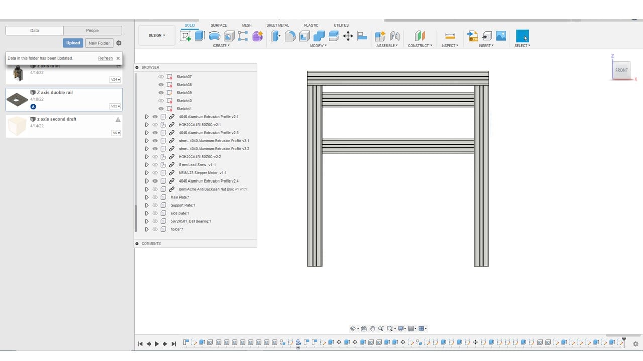
In this part, we started by collecting the fusion 360 designs of the main components of the machine from GRABCAD library. These components are stepper motor NEMA 23, 4040 Aluminum extrusion profile, 8 mm lead screw, ball bearing, 8 mm acme anti-backlash nut, and linear bearings slides and rails.I started by organizing three 500 mm extrusion profiles, as shown below. Then, I placed two shorter parallel profiles at a calculated height from the X-axis design. That height is 100 mm from the bed.
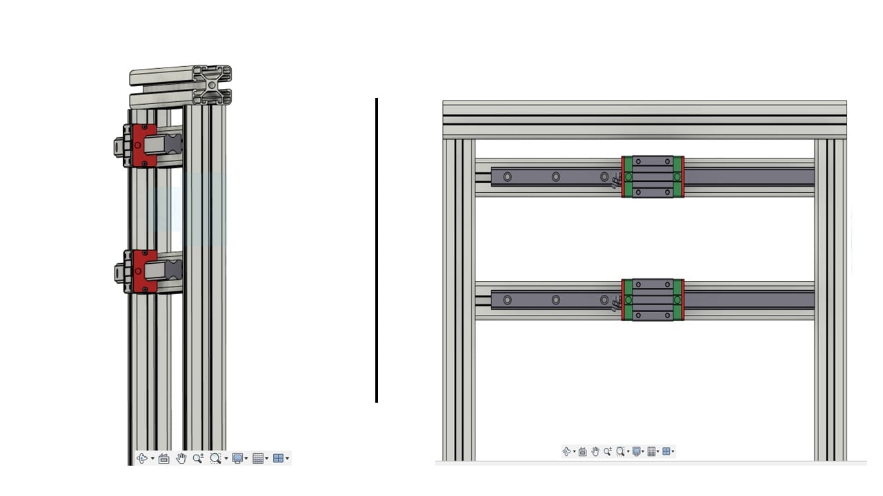
These shorter extrusion profiles' purpose is to hold the spindle and allow the CNC machine to move along the y-axis. Thus, I added a linear bearing slide and a rail for each inner profile using the "Align" tool.
I used the "Align" tool to connect the stepper motor, lead screw, and acme anti-backlash nut, as shown below.

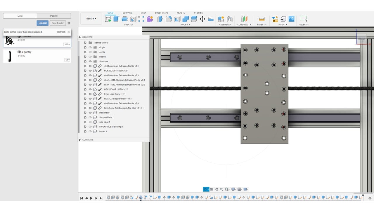
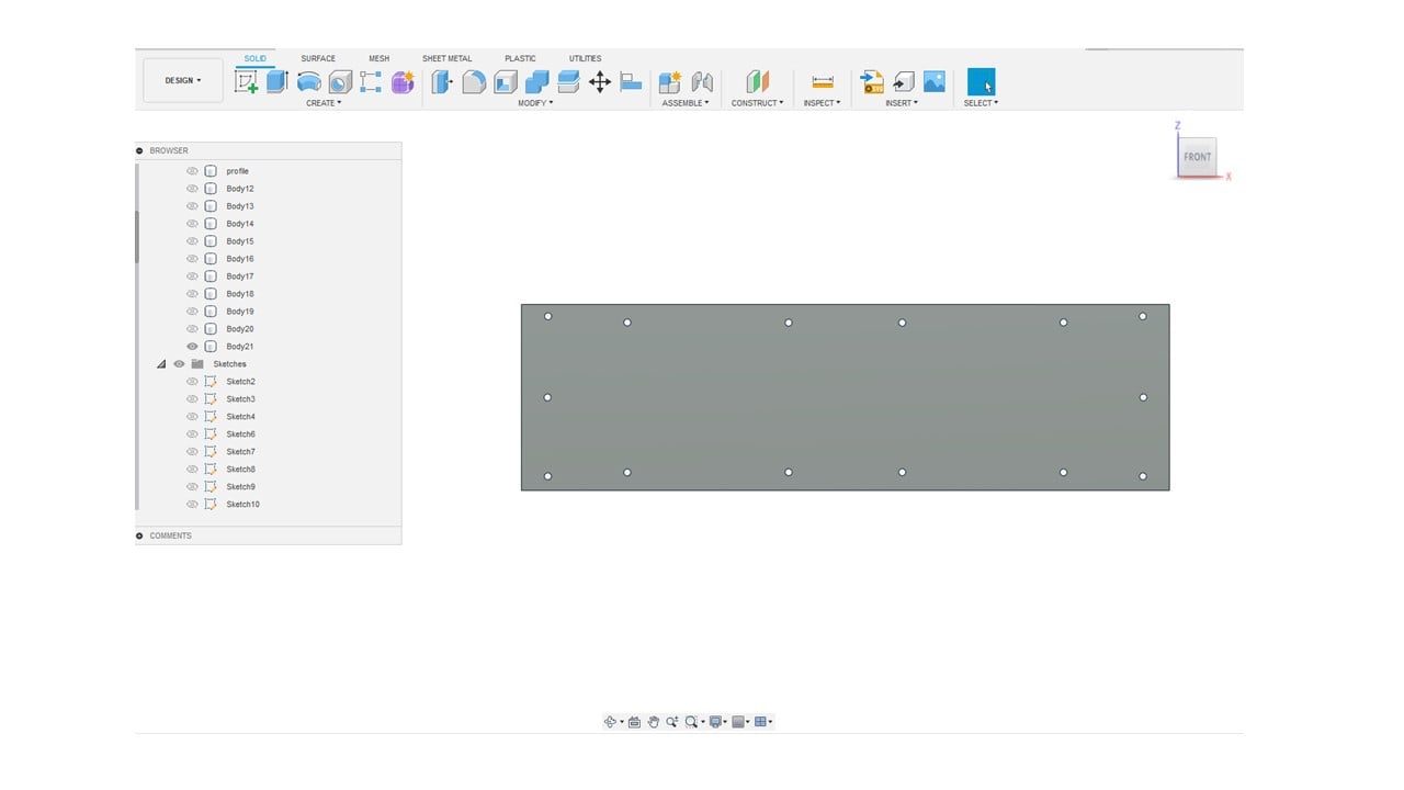
After that, I created a plate to hold the spindle and z-axis design using screws. The middle ten holes are used to fix the plate to the acme anti-backlash nut and linear bearings. These holes will allow the plate to move to the right and left.
Also, I created another plate to hold the motor in place while the machine is operating. This plate will be attached to an extrusion profile using screws.

I constructed a third plate to hold the lead screw in place using a ball bearing. Similar to the motor plate, this plate will be secured to an extrusion profile using screws.

Thus, this is the final result of the y-axis design.The engineer suggested adding a support plate behind the y-axis for reinforcement.
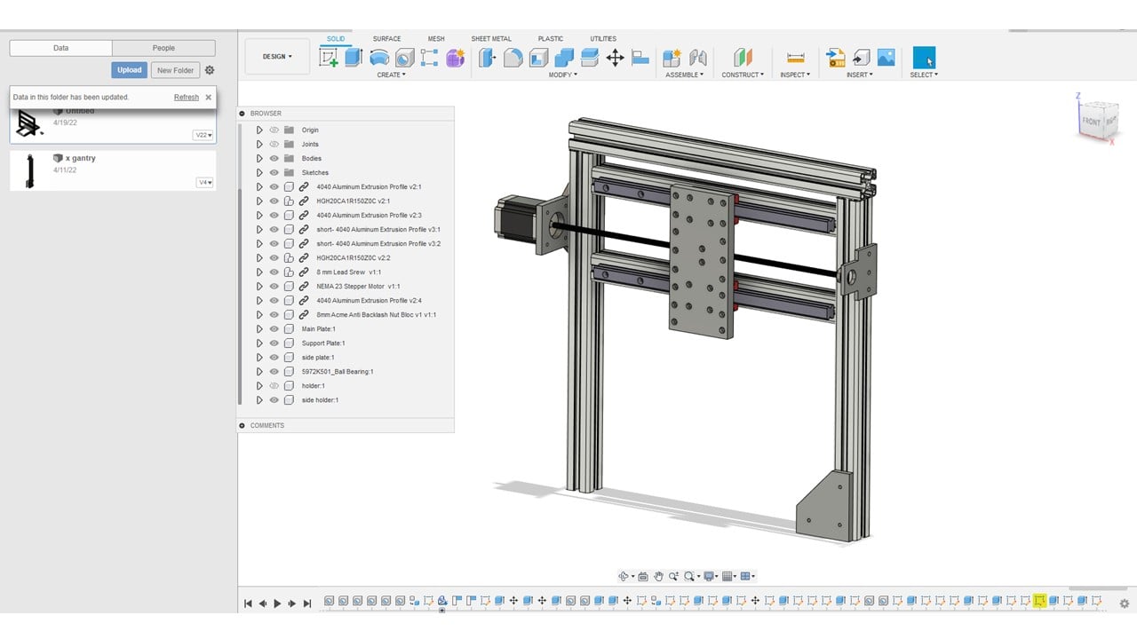
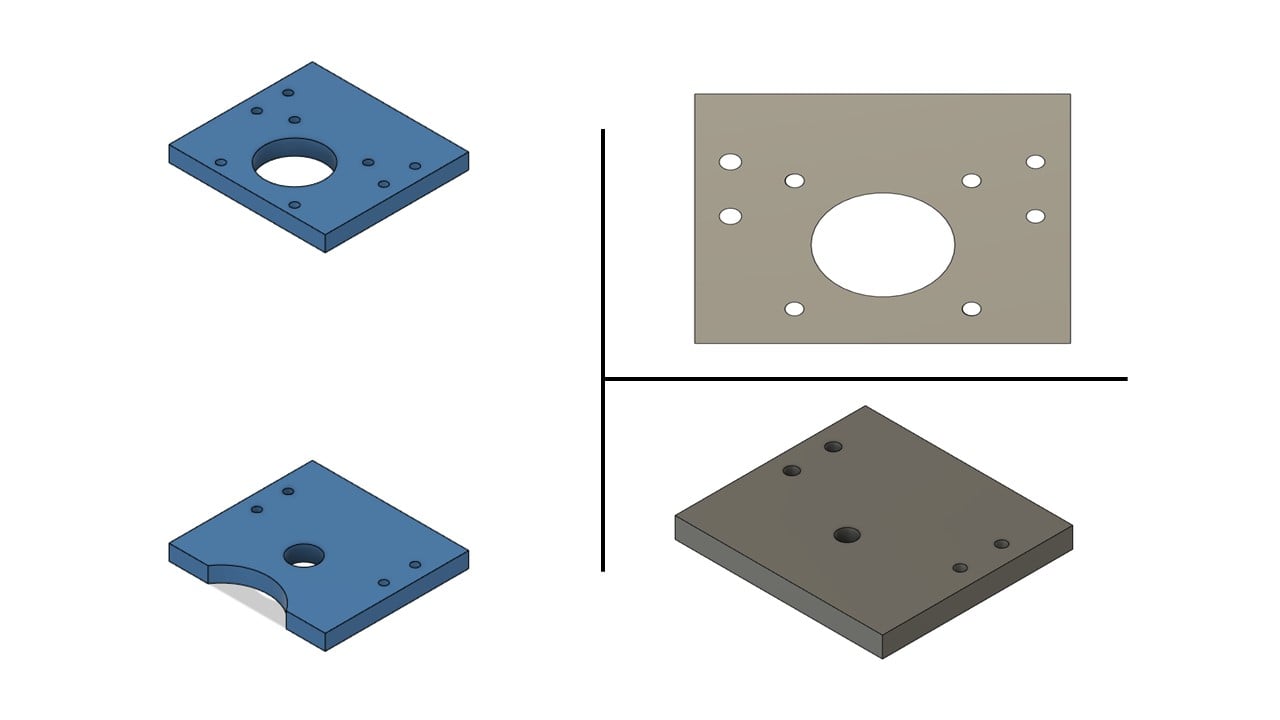
After my colleague, Ali, finished his z-axis design, I edited it to match my y-axis design. I added spindle holder screw holes at a calculated distance from the z-axis linear bearings holes.

I moved the holes of the z-axis motor and lead screw plates by 6 mm to avoid crashing the spindle plate.
b. Production and Assembly:
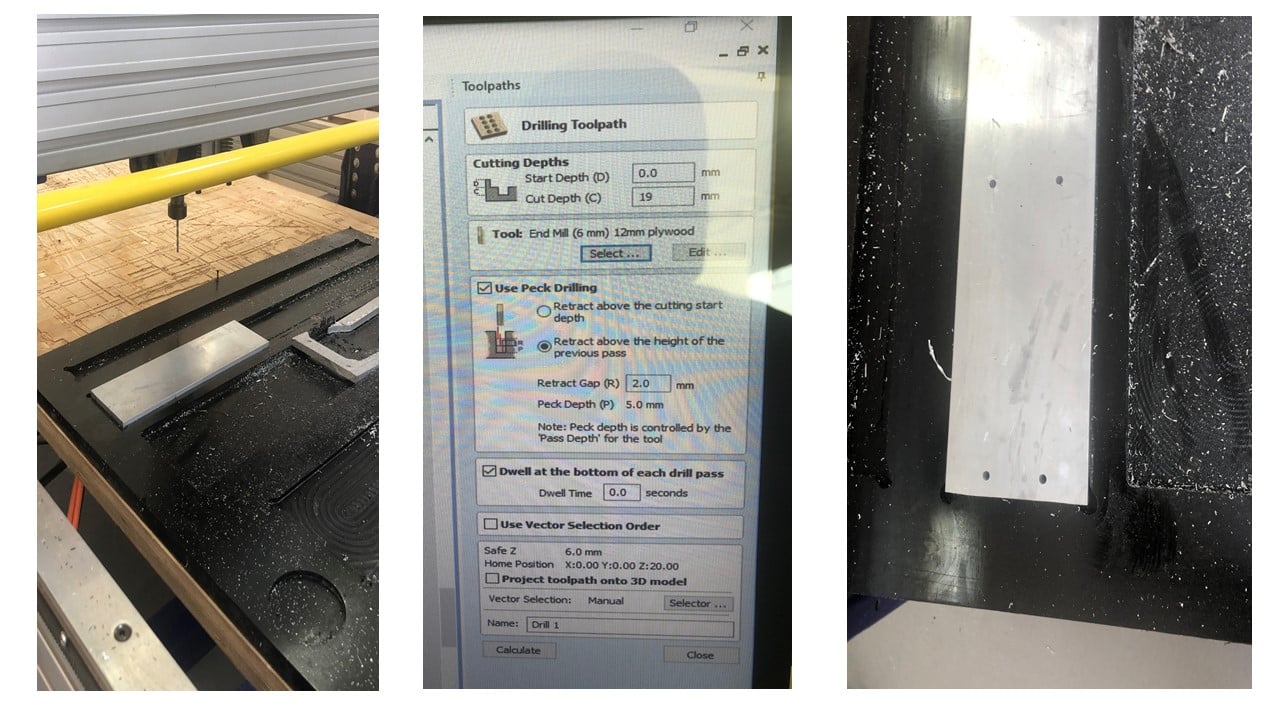
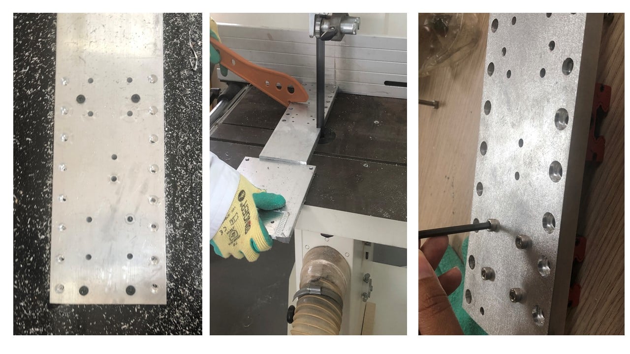
Moving to the production and assembly part, I used the ShopBot machine and VCarve software to construct the y-axis plate. To start, I drilled four holes, with the help of engineer Hashim, in an aluminum plate to not allow it to move. Then, I used a 5 mm drilling bit and drill toolpath to produce the designed holes. Then, I used a 5 mm end mill and pocket toolpath to insert the head of the screws into the plate.

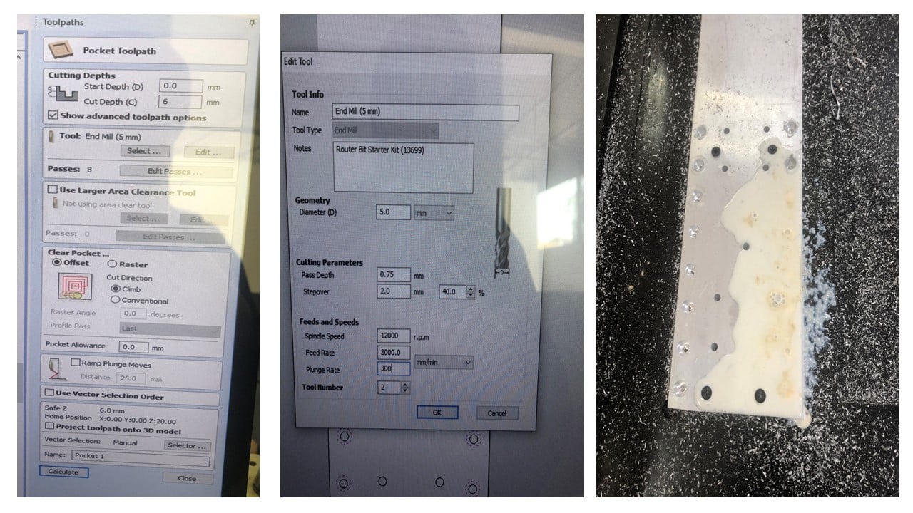
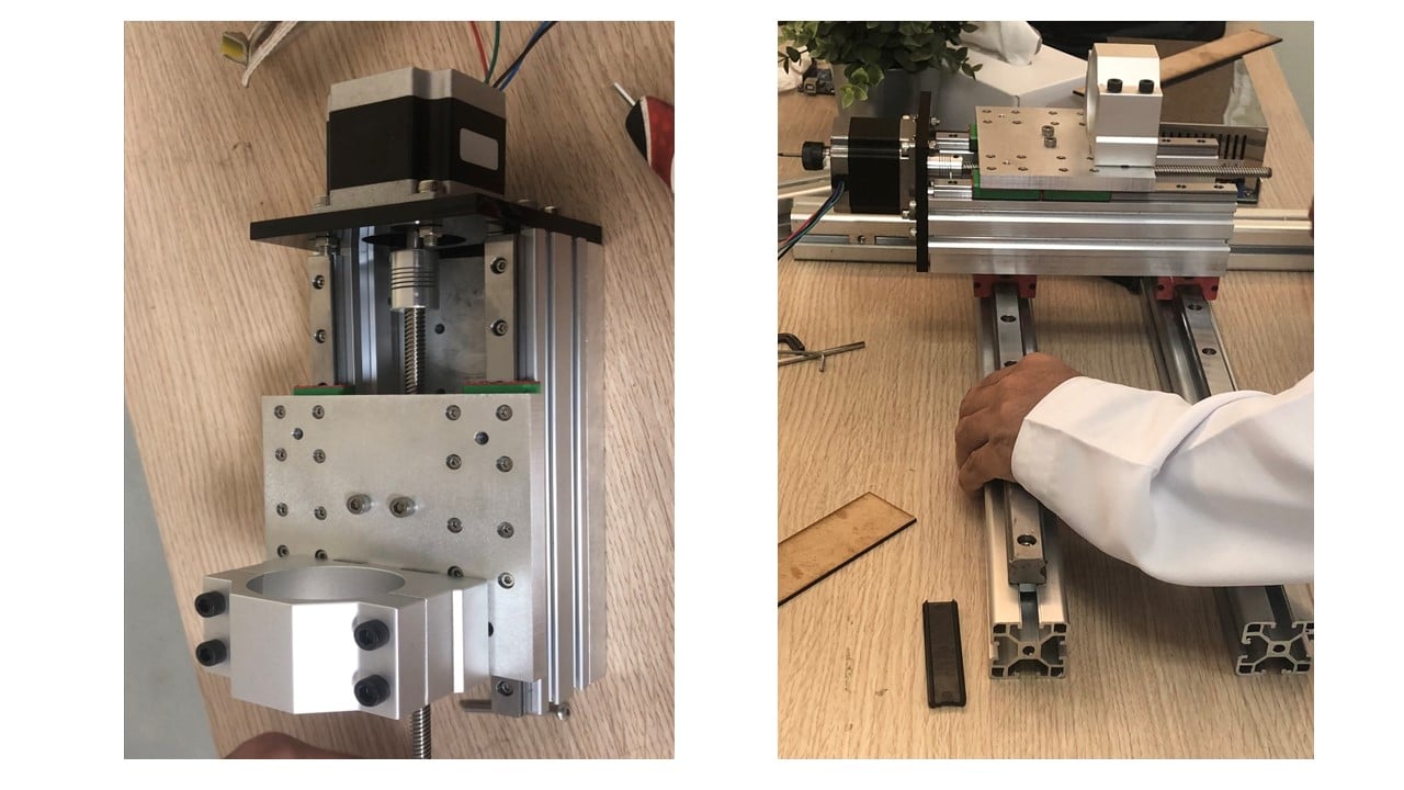
After that, I removed the fixing screws to cut the plate to the desired length. After a minor sanding process, I attached the linear bearings to the plate using screws.
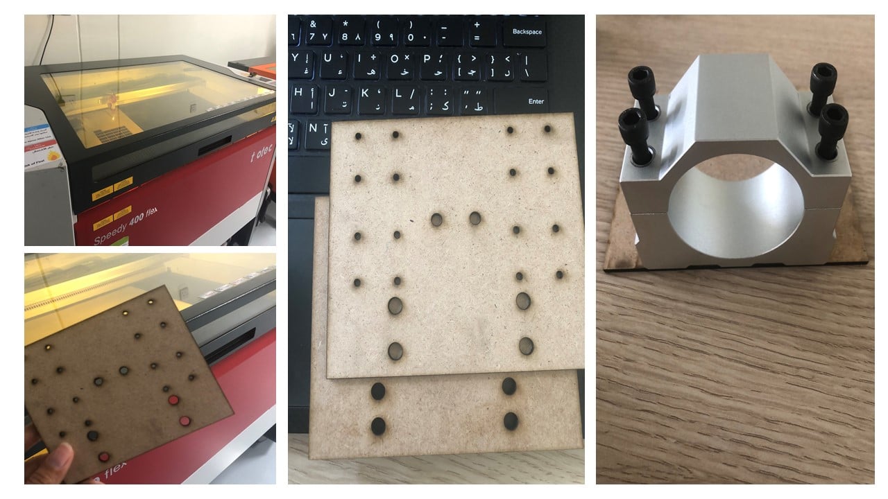
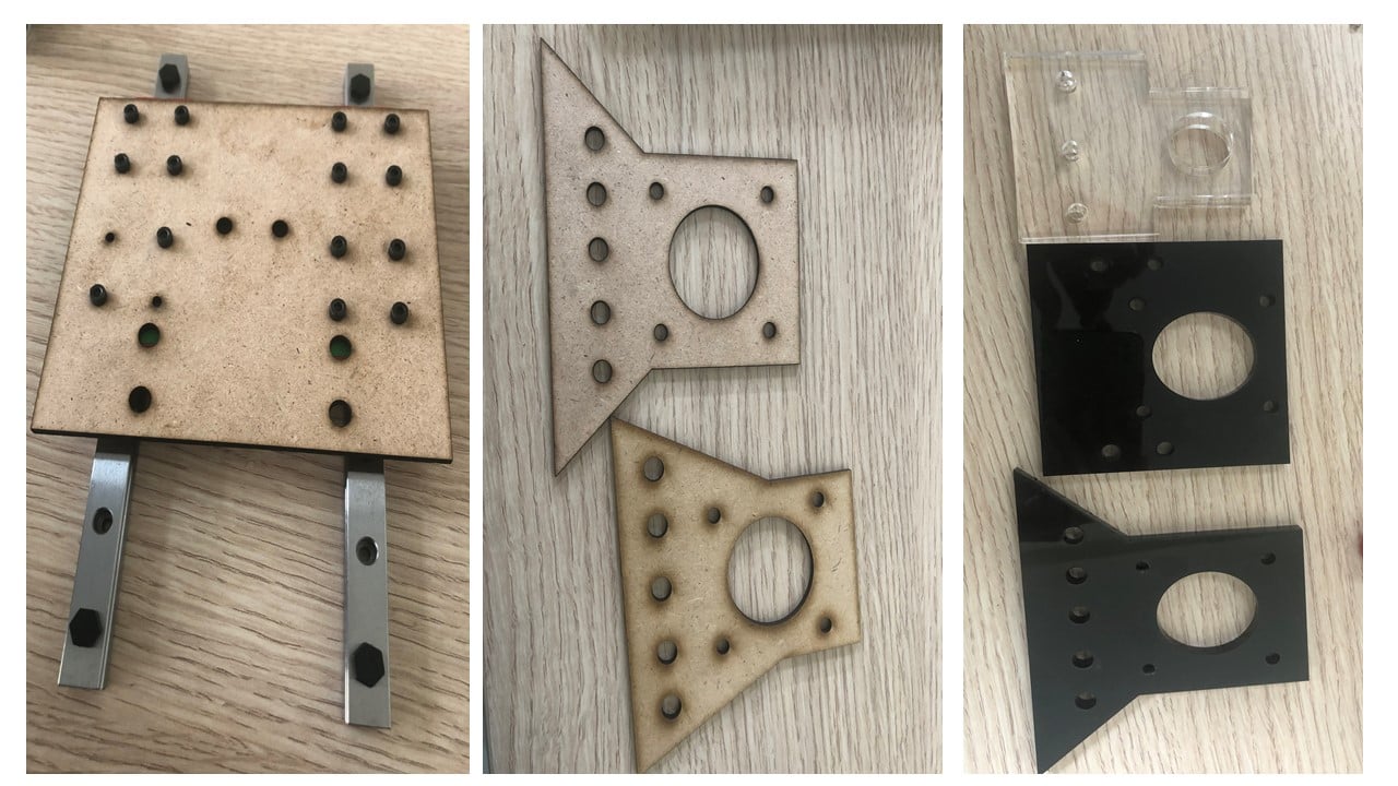
To create the spindle plate, motor plate, and lead screw plate, I used a laser cutter machine and MDF wood to ensure that the dimensions were correct. After a trial and error process, I created these plates using a laser cutter and acrylic sheets.
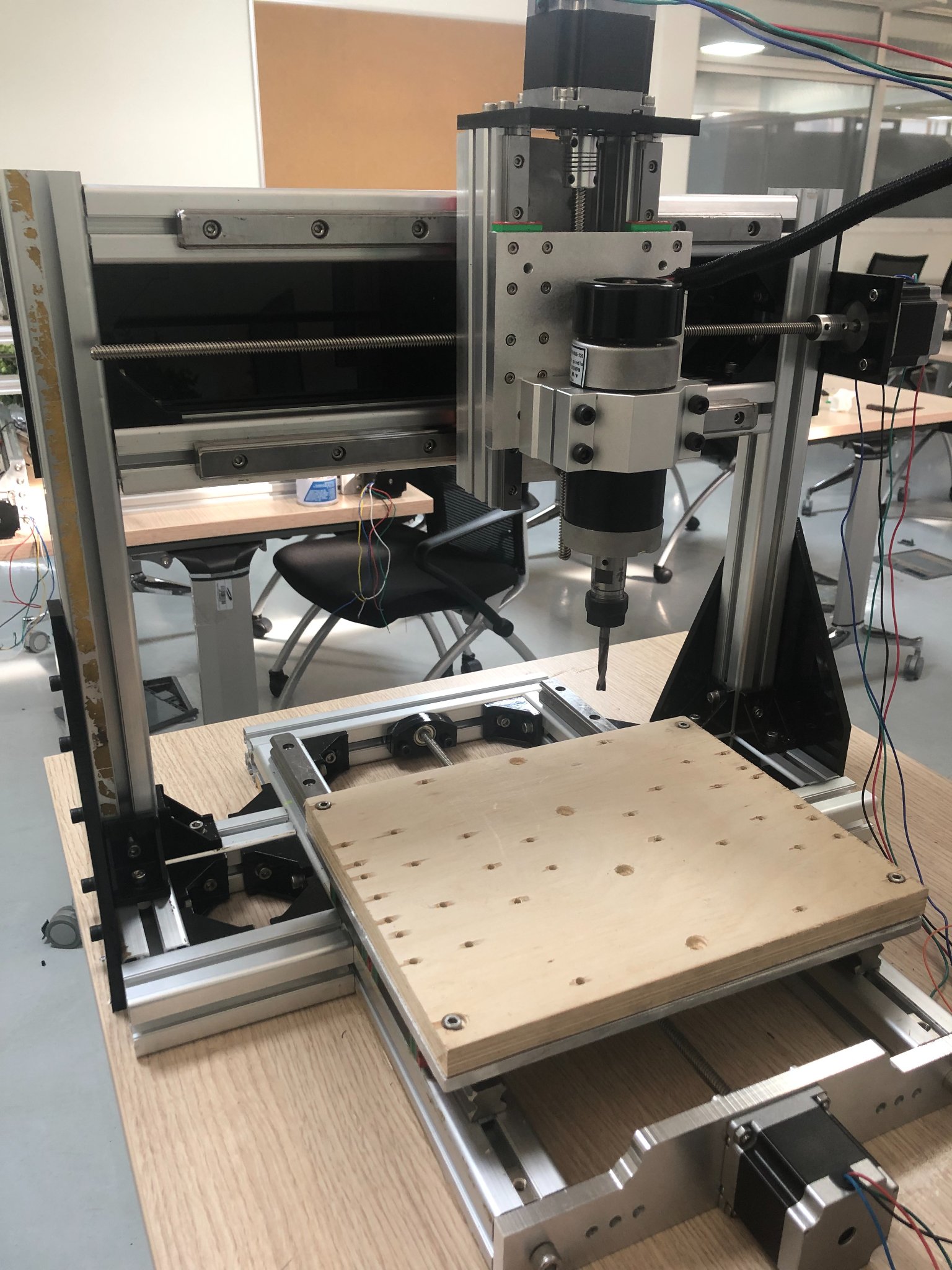
Then, I assembled the y and z-axis using the help of engineer Hashim and my colleague Yousef.
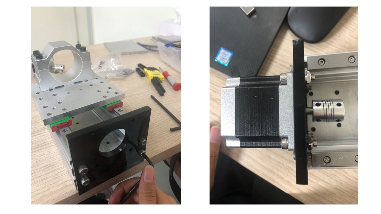
The final result is shown below.
# Challenges:
The main challenge I faced was the time required for constructing a machine was longer than expected due to the trial and error process to produce some parts.