10. Moldeing and Casting
# Goal:
Design a mold and produce cast parts.
# Tasks:
1- Design the mold using Fusion 360 software.
2- Mill the mold using Roland SRM-20 CNC machine and machinable wax.
3- Fabricate casted parts using the created mold.
# Procedures:
This week engineer Hashim gave us a workshop about designing a two-part mold using Fusion 360 software. I started by designing the mold using the design and manufacturing workspace, then cut it using Roland SRM-20. After that, I mixed the silicon rubber to create the mold and the liquid plastic to make the cast parts.
a. Mold Design:
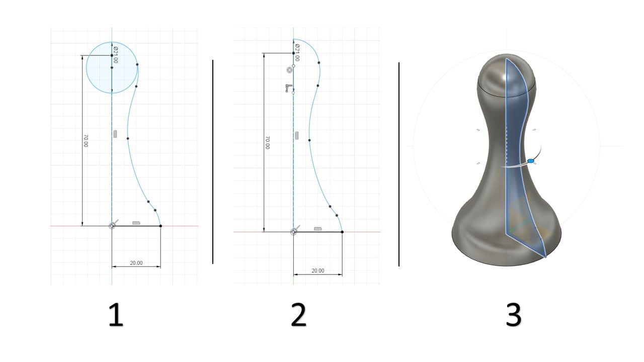
I chose to design a pawn used in chess since it is easy to sketch and needs a 3-axis finish cut. I had a detailed picture in mind. However, the engineer recommended reducing the details in the design to ensure a clean cut by the CNC machine. So, I started by drawing a half outline of the actual design. Then, I used the "Revolve" tool to rotate this outline for 360 degrees.
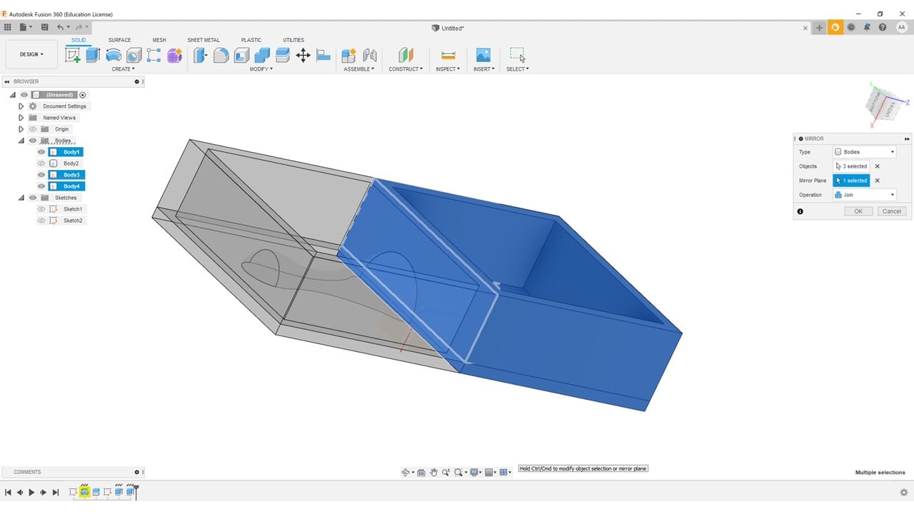
After that, I split the body using the "Split Body" tool. I used the resulted half of the body to sketch the mold, starting with the frame and the base. Then, I extruded both of these parts.


Then, I duplicated the whole design using the "Mirror" tool to create the other half of the mold.
After that, I sketched the spherical connectors, cast inlet, and the bubbles outlet. I created a sphere in each indicated place of the connectors. These connectors will help me fix the mold during the casting process. I cut the spheres on one side while I joined them on the other. Then, I extruded the inlet and outlet.

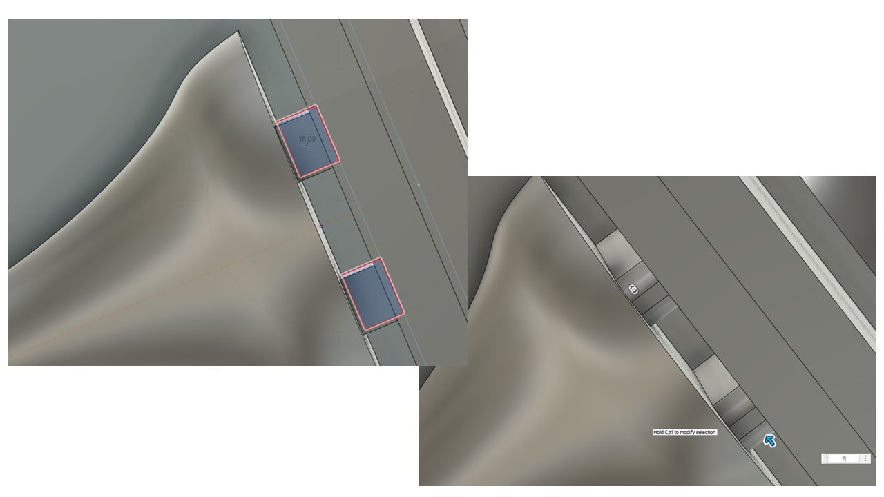
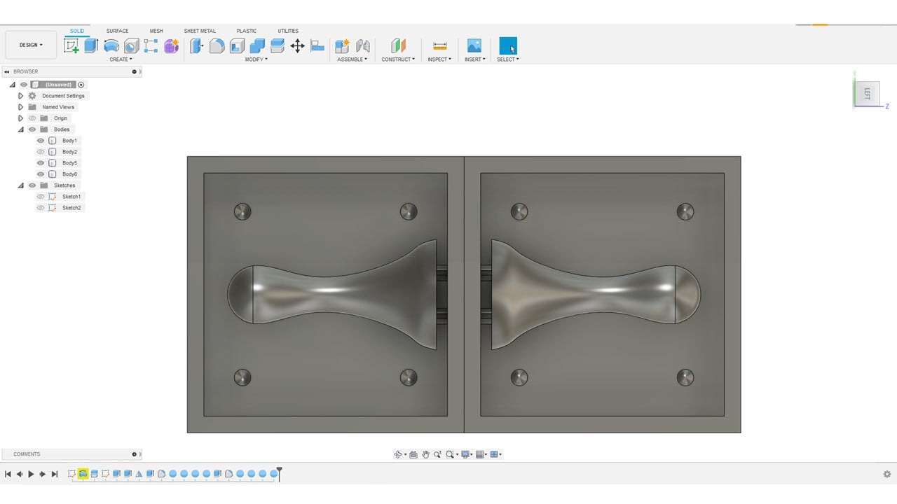
The final step here was duplicating the connecters and the inlet and output to the other half of the designed mold.
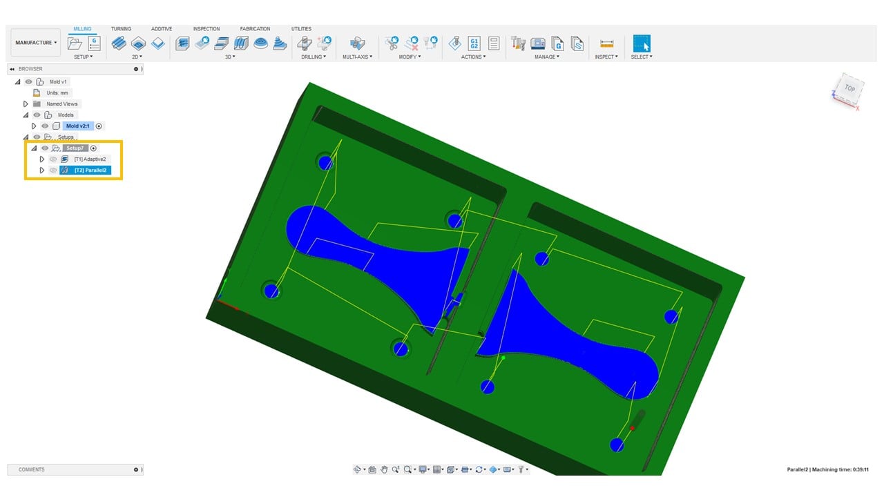
b. CAM:
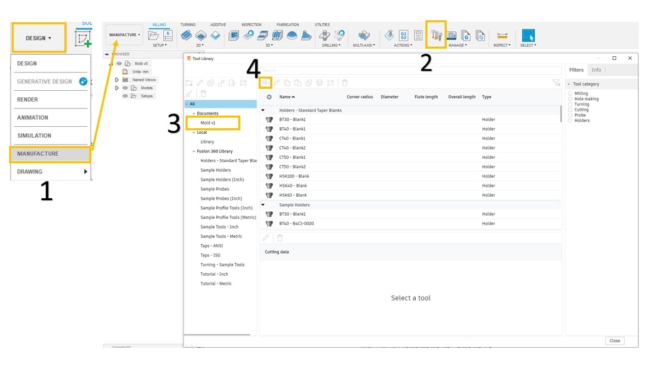
Fusion 360 software has a strong reinforcement for computer-aided manufacturing (CAM), which enables the user to convert designs into physical reality. I started by converting the workspace in the software to "Manufacture". Then, I chose "Milling", "Manage", and "Tool Library" to insert all the details about the two milling bits I am going to use. These milling bits are 1/8 inches Flat end mill and 1/8 inches Ball nose end mill. I clicked on the design file and the plus icon.
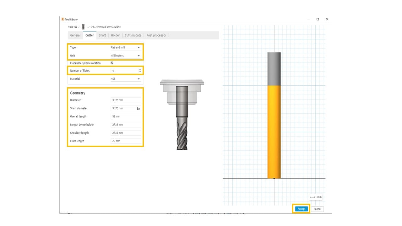
The first milling bit is the flat end. Thus, I selected it from the "New tool" list. Then, I clicked on "Cutter" to describe its properties. I changed the units to millimeters and the number of flutes to 4. In the geometry part, I adjusted the diameter and the shaft diameter to 1/8 inches, which equals 3.175 mm, since the used mill does not have a shaft. After that, I measured the milling bit length and flute length using a ruler. Also, I fixed the shoulder length and the length below the holder to 27.16 mm.

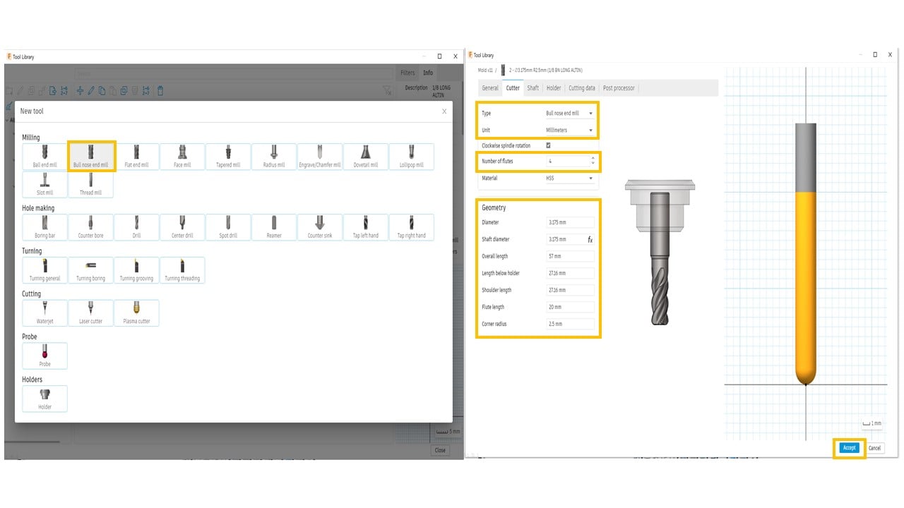
The second milling bit is the bullnose end. Thus, I selected it from the "New tool" list. Then, I clicked on "Cutter" to describe its properties. I changed the units to millimeters and the number of flutes to 4. In the geometry part, the dimensions are similar to the previous milling bit.
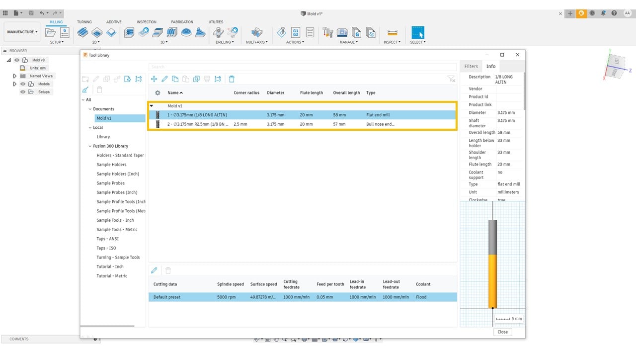
Now, the tools appeared in the "Tool Library" of the mold design.
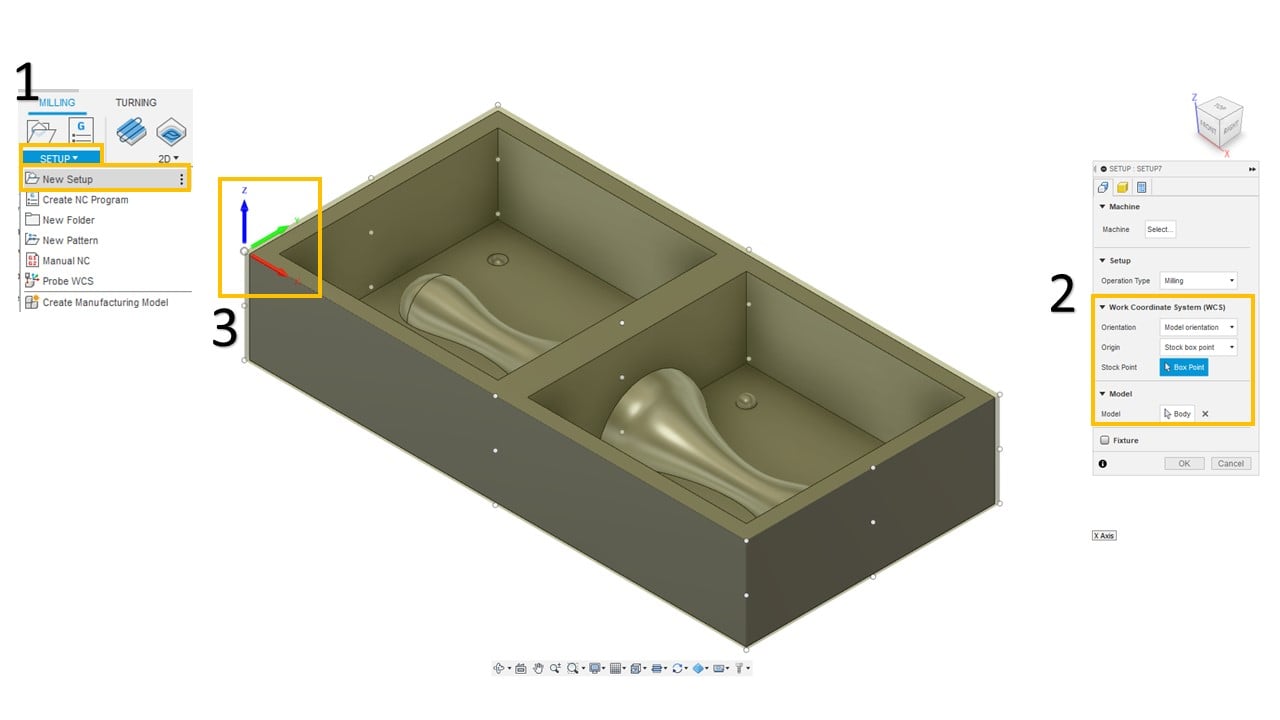
To select the origin, I clicked on "New Setup". Then, I chose the body as the model, the stock box point as the origin. After that, I clicked on the left upper corner as the stock point.
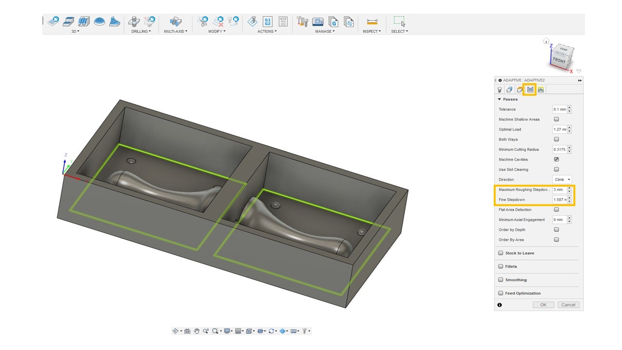
In the 3D milling, I started with adaptive clearing, which is a roughing technique to remove large quantities of a selected material. I selected the flat end mill as the tool. Then, I adjusted the spindle speed and the ramp spindle speed to 8500 rpm. After that, I fixed the cutting, lead-in, and lead-out feed rates to 1000 mm/min.

In the geometry part, I removed the rest machining check and selected the machining boundary as the bases in the mold.

I fixed the heights as shown below. Moving to the passes section, I changed the maximum roughing stepover and the fine stepdown to 3 mm and 1.587 mm, respectively.

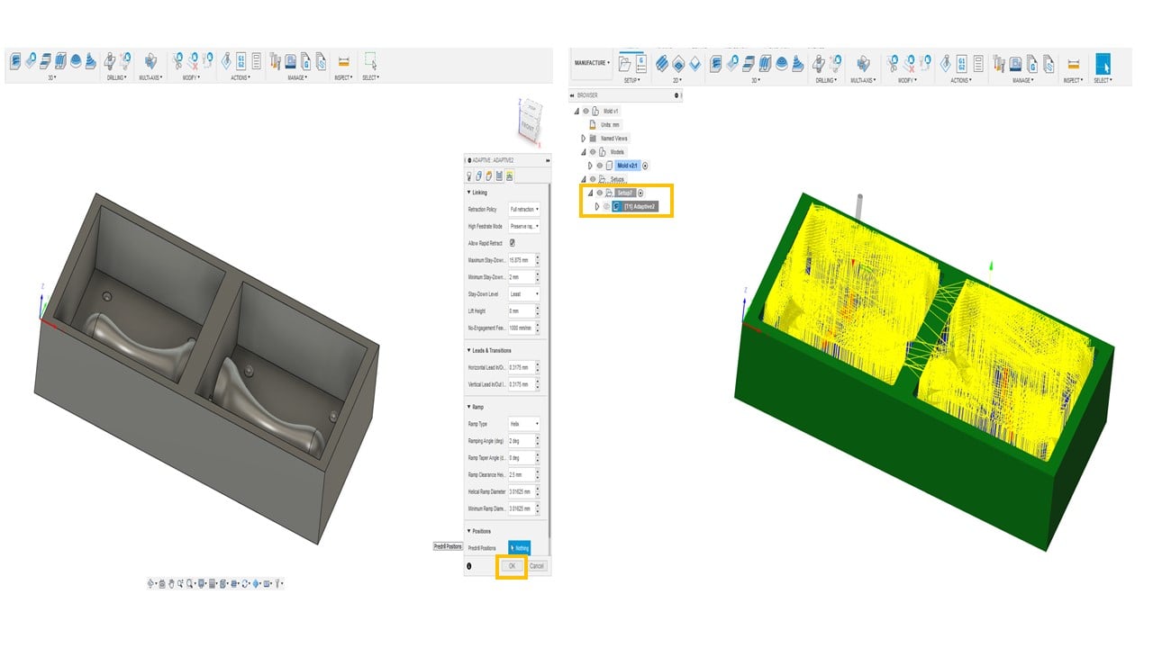
I clicked on "OK" and waited for the adaptive cleaning toolpath to terminate.
Parallel finishing passes are the best to give a smooth finishing to the areas of the design with details. Thus, I added a parallel toolpath. The tool used here is the bull nose end mill. I fixed the feed rates and speed to the previous toolpath.
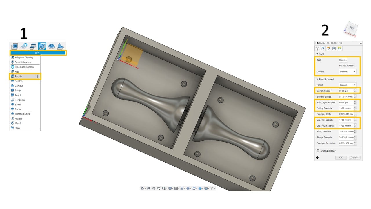
In the geometry part, I selected the machining boundary as the pawn, the connectors, and the inlets and outlets. Moving to the passes section, I fixed the stepover to 0.1 mm.

I clicked on "OK" and waited for the parallel toolpath to terminate.
To extract the toolpath files from the software, I clicked on "Actions" and "Post Process". Then, I chose the post as Ronald RML, and the machine type as MDX-40.

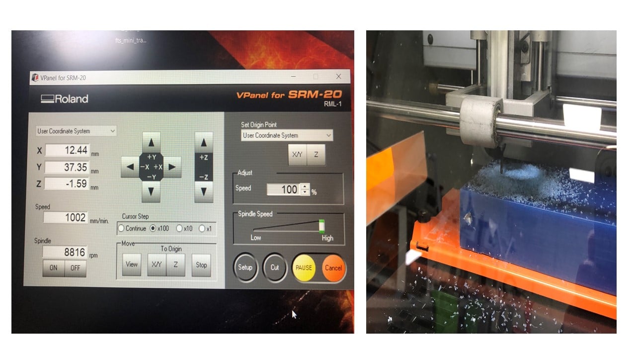
c. Milling:
I started by cutting the machining wax based on the mold design dimensions. Then, I placed the wax inside the Roland SRM-20 CNC machine and ensuring it was flat using the screws.I used the flat end mill to create the adaptive cleaning toolpath and the bullnose end mill for the parallel toolpath.

Using V-panel, I selected the origin point (X, Y, Z) by clicking on the arrows. This point was selected based on the available space on the wax. After that, I clicked on the cut button and added the mold files to start milling.
The final result of the milling is shown below.
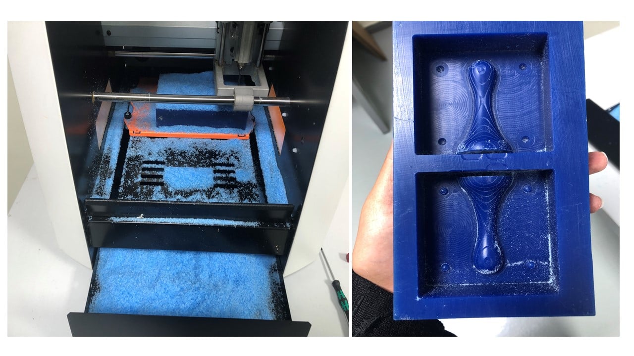
d. Molding:
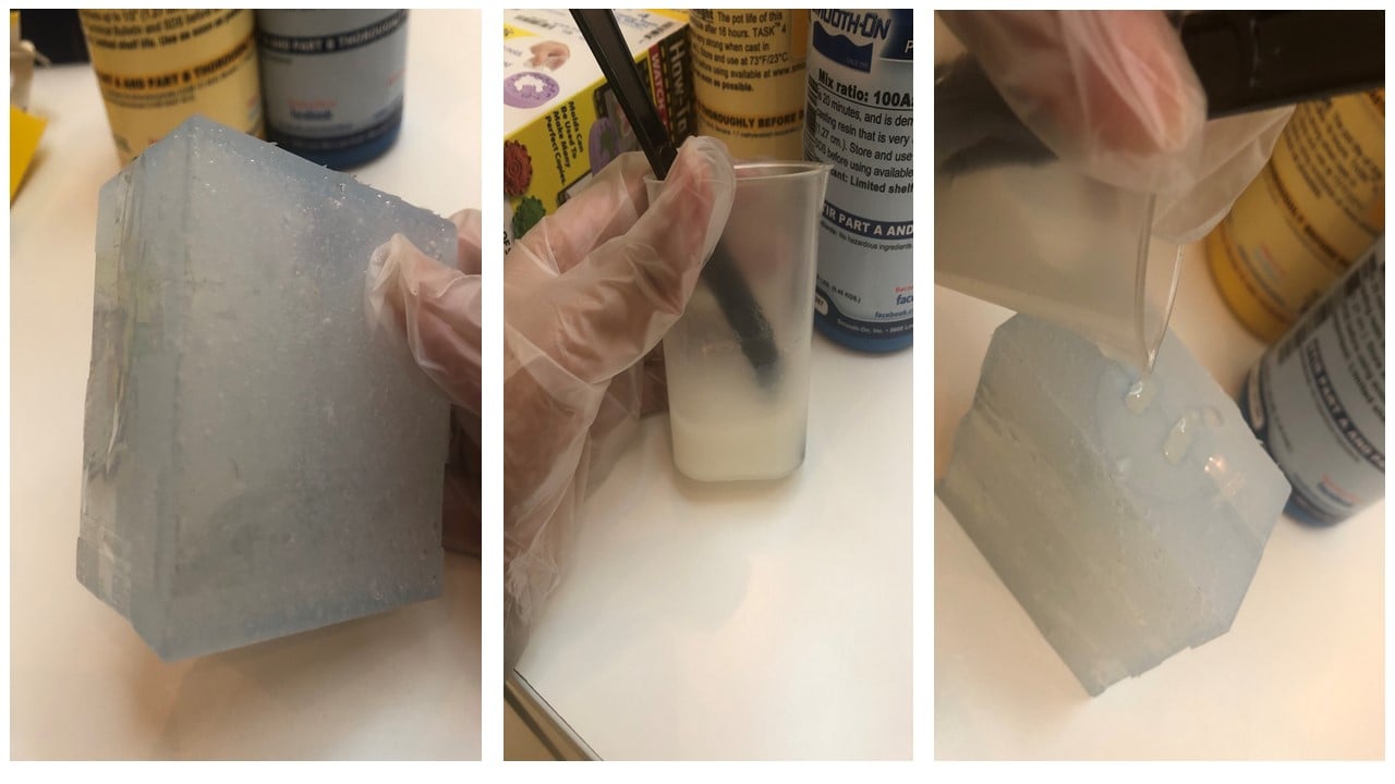
To create the mold, I used the Sorta-clear 37 Silicon Mold rubber. I started this process by wearing a lab coat, safety goggles, mask and gloves.

I used water to estimate the amount of material needed to create the mold. Then, I mixed half of the amount from liquid A and B because their mix ratio is 100A:100B.

I pour the mixture slowly to cove the wax. Then, I waited for 4 hours to allow it to dry. The resulting mold is shown below.

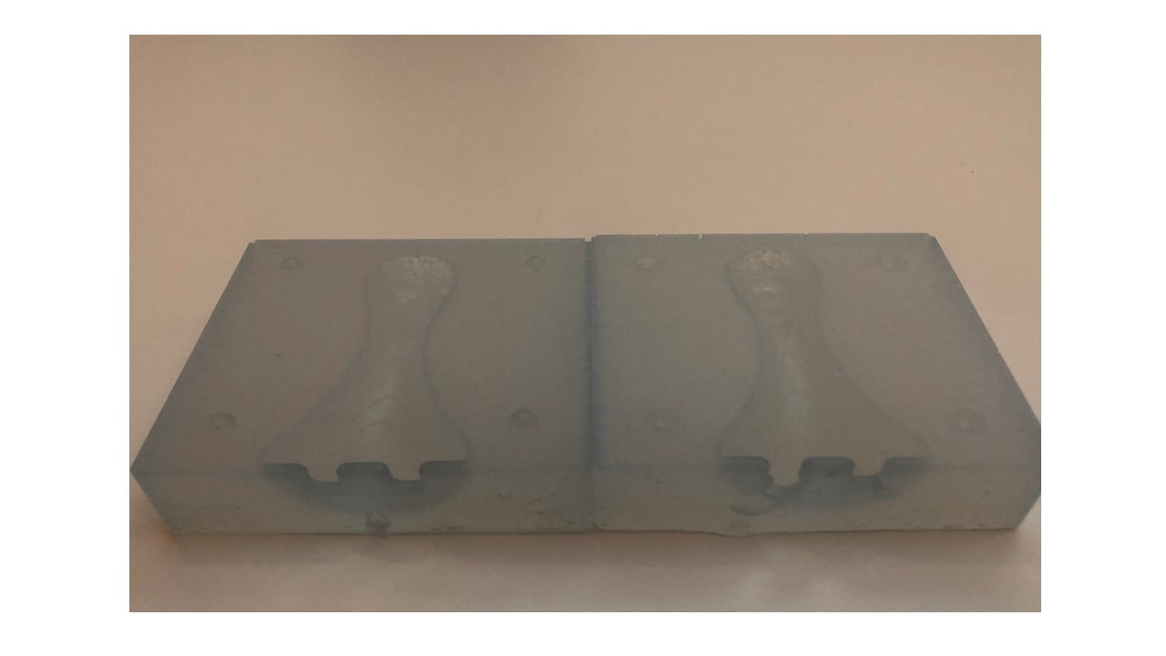
e. Casting:
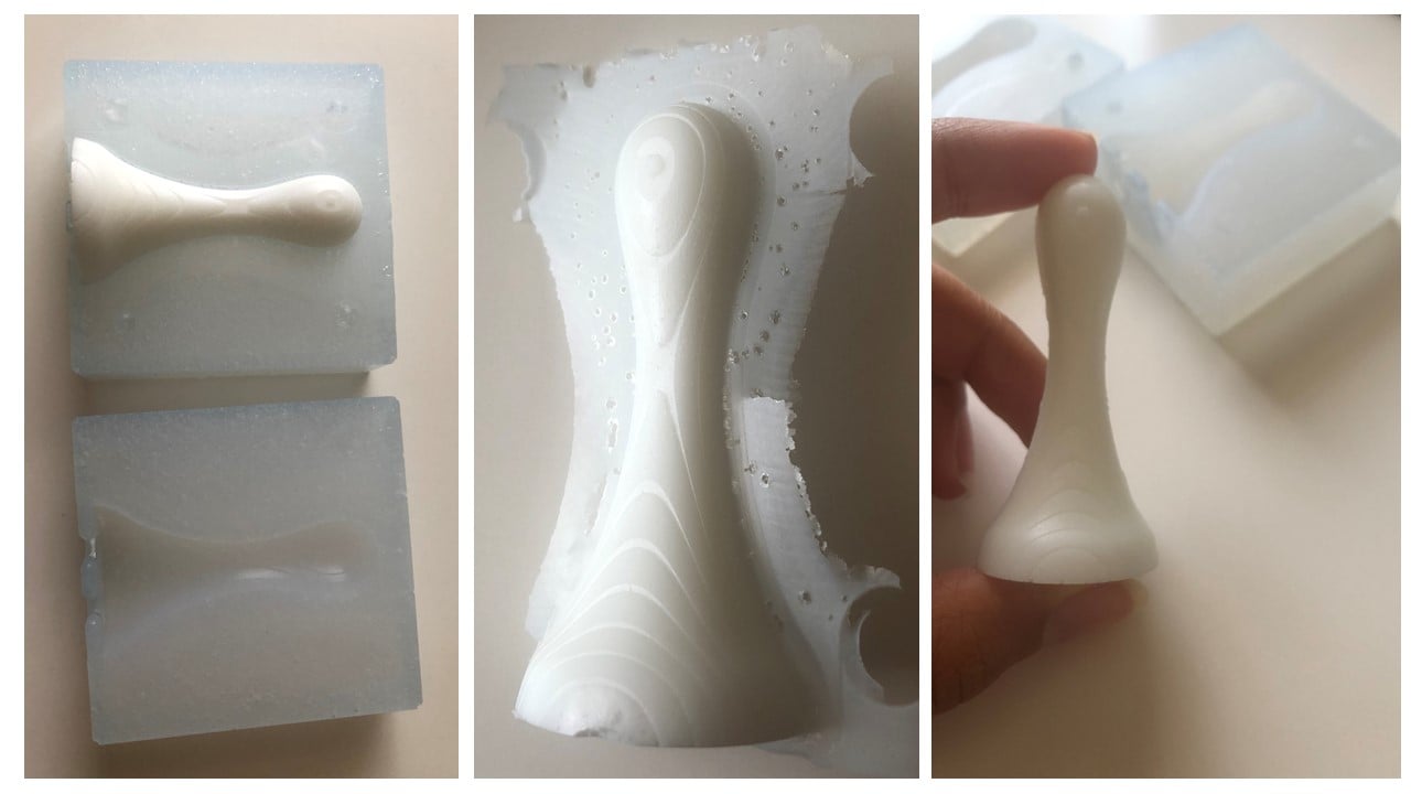
To create the mold, I used Task 4 Urethane Casting Resin. Similar to the molding phase, I followed the safety procedures.

I ensured that the two parts of the mold closed tightly by using a tap. Then, I used water to estimate the amount of material needed to create the mold. I mixed half of the amount from liquid A and B because their mix ratio is 100A:100B. After that, I pour the mixture slowly.
I waited for 16 hours to allow it to dry. The resulting mold is shown below before and after sanding.
Group Assignment
The link of the group assignment page is here.
# Goal:
Learn about the safety precautions needed while using molding and casting materials.
# Task:
Read the safety data sheet of the molding and casting materials and compare them.
# Procedures:
I chose Sorta-clear 37 Silicon Mold rubber for the mold and Task 4 Urethane Casting Resin for the cast. Thus, I read the safety data sheet for the mold and cast materials.
Sorta-clear 37 Silicon Mold contained no hazardous ingredients in both parts A and B. When storing this material, we should keep it closed tightly with a clear label in a cool, dry, and well-ventilated place. There is no respiratory protection needed while using this material in open environments with adequate ventilation. However, there is a need to wear liquid-tight gloves and goggles. Also, extra protective clothing is not a necessity. It is highly recommended to have good personal hygiene after handling the material.
Task 4 Urethane Casting Resin part A is classified as dangerous that can cause skin and eye irritation and asthma symptom if inhaled. Thus, air-purifying respirators are needed. Also, there is a need to wear liquid-tight gloves and goggles. Moreover, extra protective clothing and good personal hygiene are recommended. On the other hand, part B contained no hazardous ingredients.
While using both materials above, I wore a lab coat, safety goggles, mask, and gloves.
# Challenges:
The main challenge I faced was the long cure time required for the silicon rubber and liquid plastic to dry. Thus, I worked on my documentation during this time.
# Files:
1- Mold Design