5. Electronics production
0.2 mm Tool Diameter Amal Ashoor
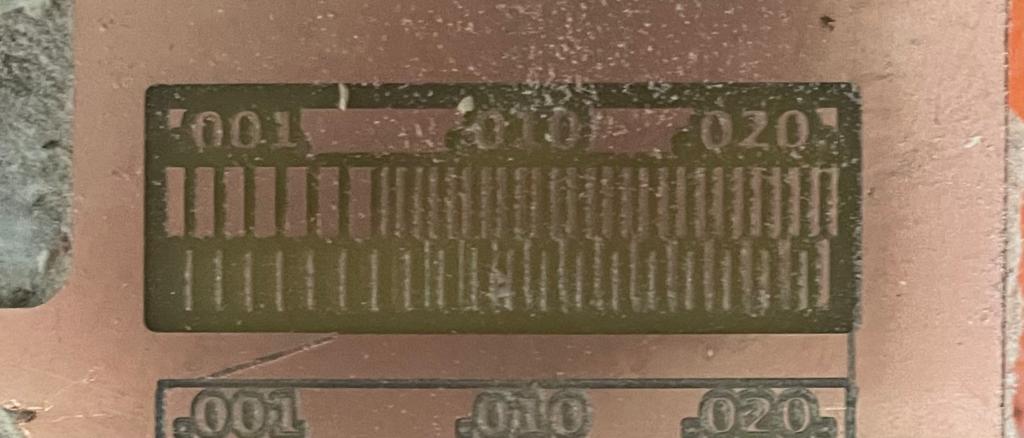
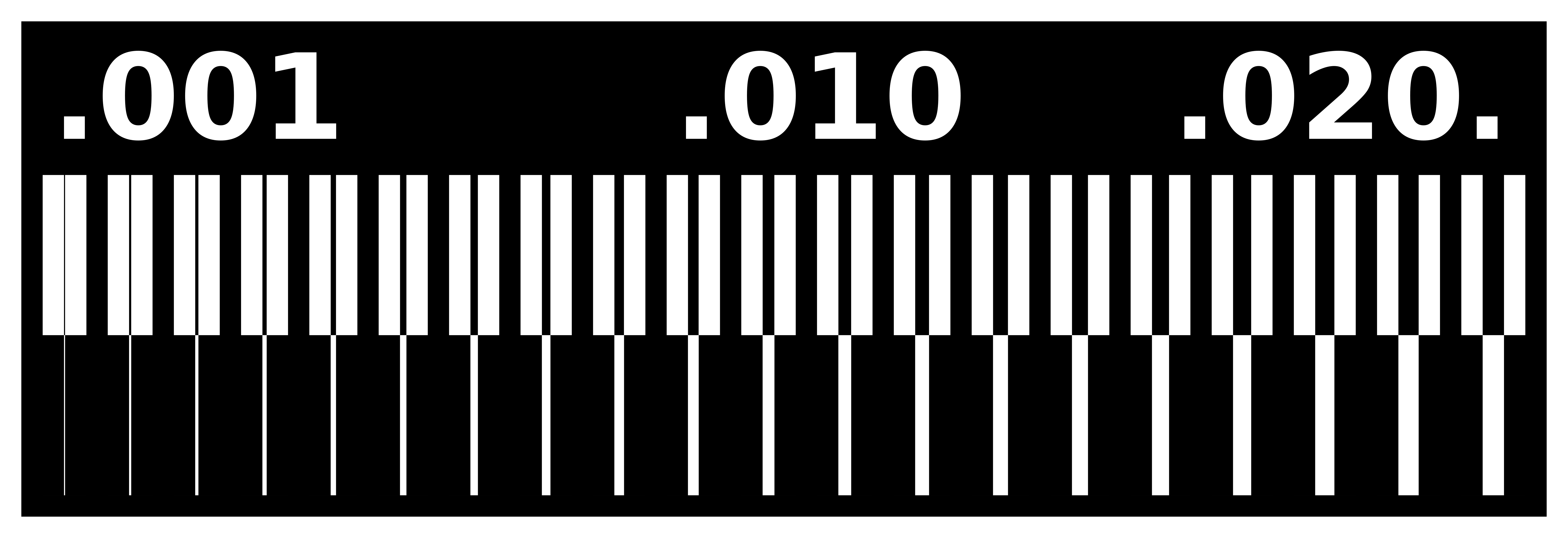
The goal of this week assignment is to describe the design rules using the Roland SRM-20 CNC machine CNC machine. To start the fabrication process, I downloaded the interior and the traces in PNG format from this website.
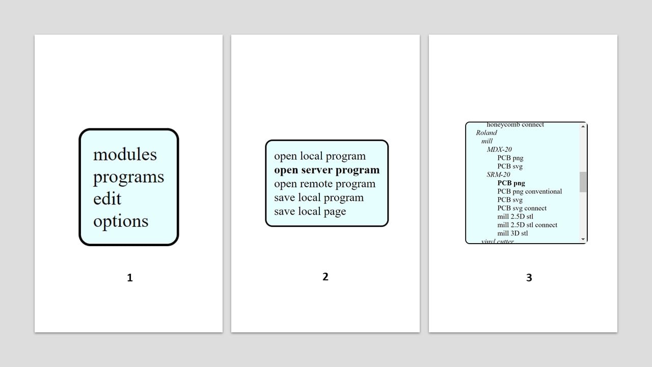
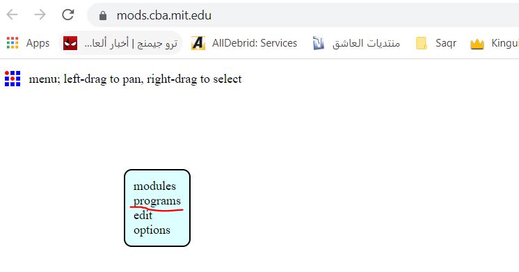
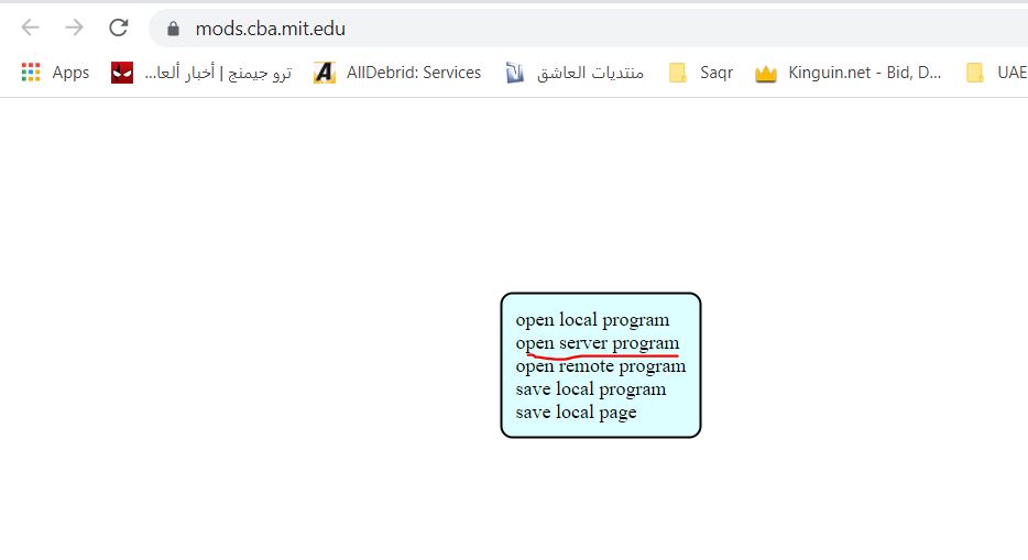
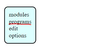
 To change the PNG images to Ronald mill (.rml), I mainly used this website. I started by right-click then I selected “Program”, “Open server program”, and “Roland mill SRM-20 PCB png”.
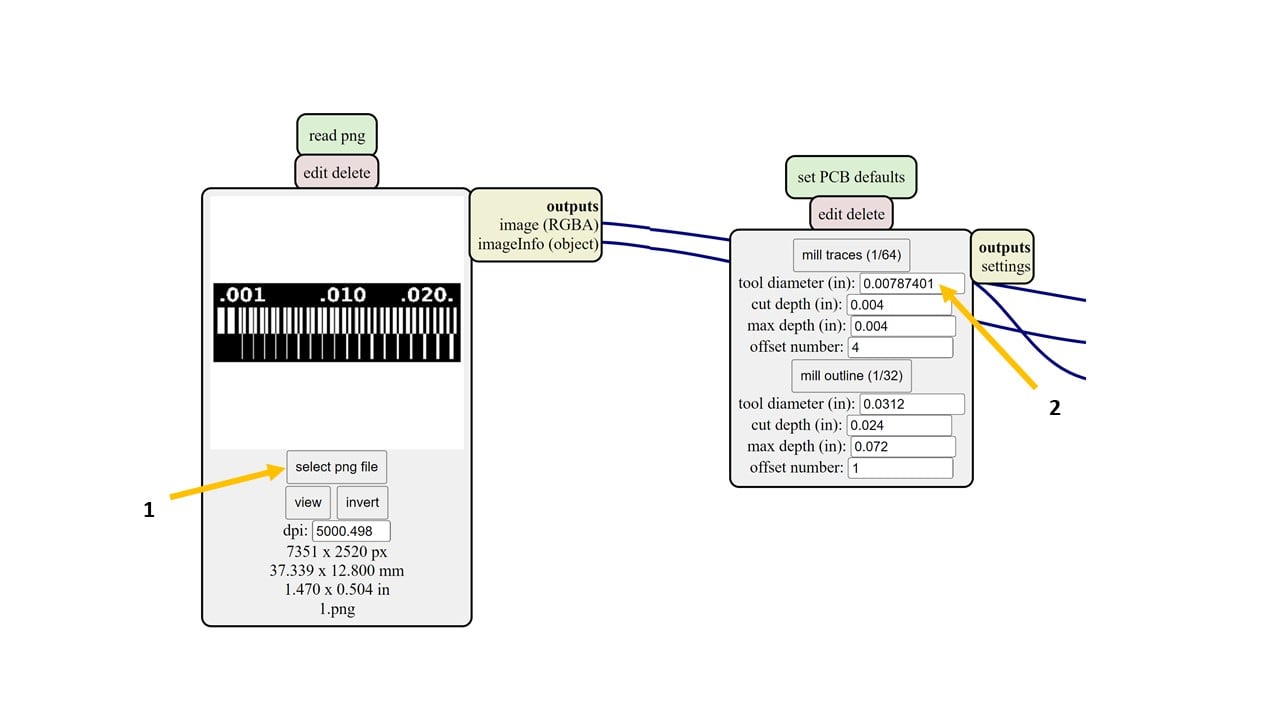
 After that, I selected the traces png file and changed the tool diameter to 0.2 mm which equals , which equals 0.00787401 inches.
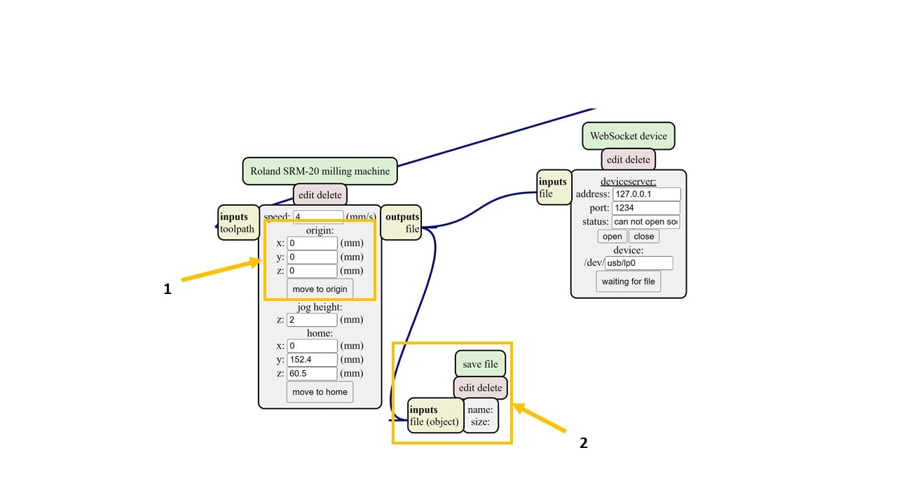
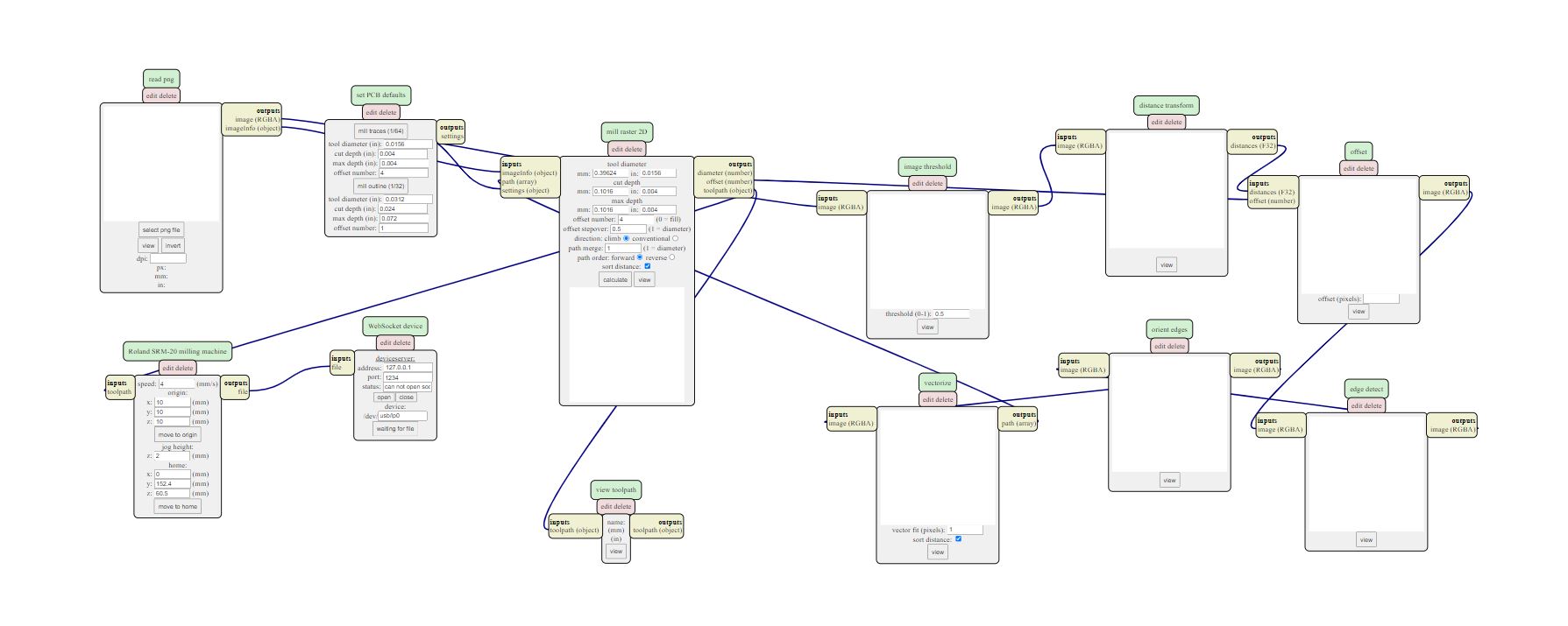
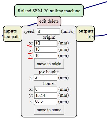
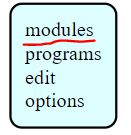
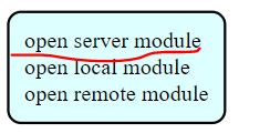
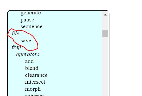
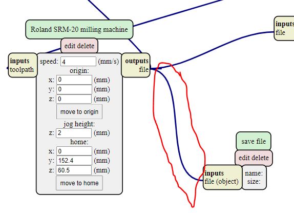
 I changed the origin of the machine to zero on all axis. To save the output file, I right-clicked on the page and selected “Modules” and “Open server module” and “file save”. Then, I connected the input and output as shown below.
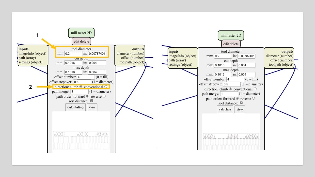
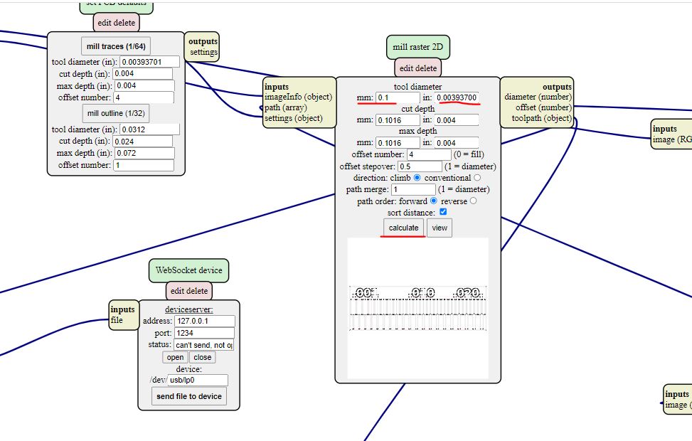
 Moving to the mill raster 2D, I changed the tool diameter to 0.2 mm and the direction to climb. Then, I pressed on calculate and saved the (.rml) file. I repeated this step in the conventional direction. Then, I changed the png file to the interior and repeated this step in the two directions.
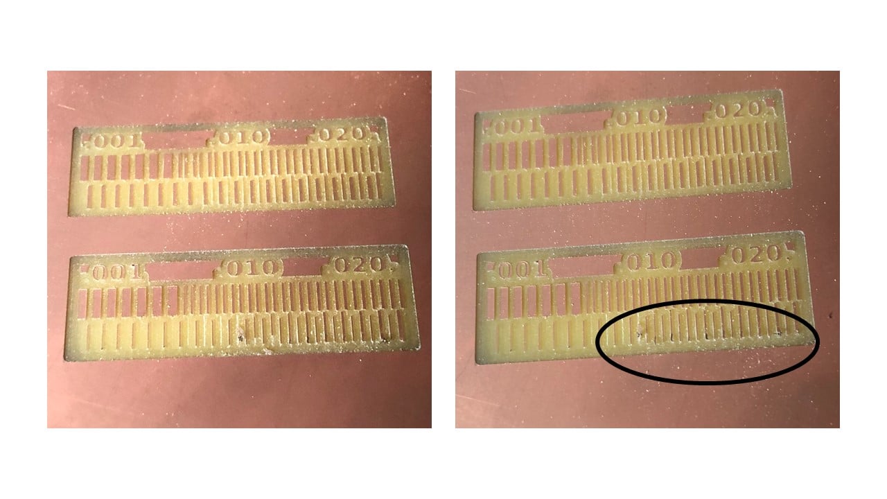
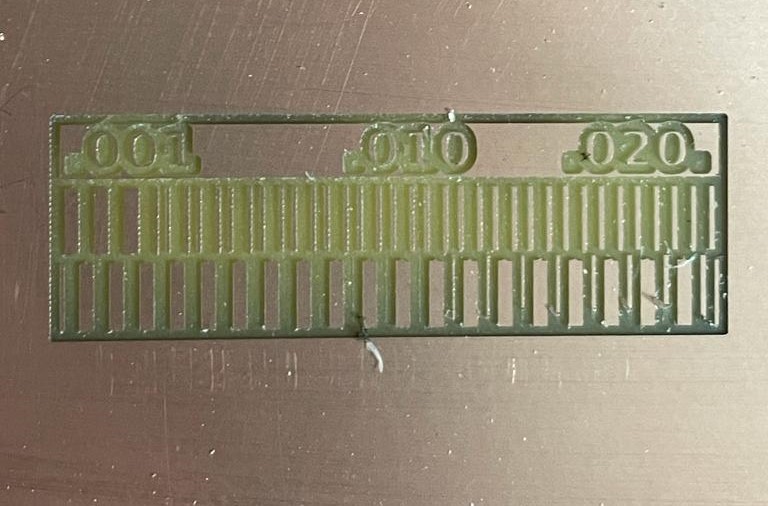
 I changed the milling bit of the machine to 1/64 milling bit and selected the origin point. Then, I cut the climb files first then the conventional files. The results are shown below (top is the climb direction). According to the following image, the climb direction milling is clearer compared to the other one.
<<<<<<< HEAD
4255d2635aa16b1cb2a9e0e8819f10f8b977a776
Yousef Jalil 
For the Group assignment we had to test the capabilities of the Machine (Roland SRM-20) to mill extra fine details. also through different milling directions (Climb and Conventional)
I downloaded the traces provided to test the machines from Here.
Linetest traces
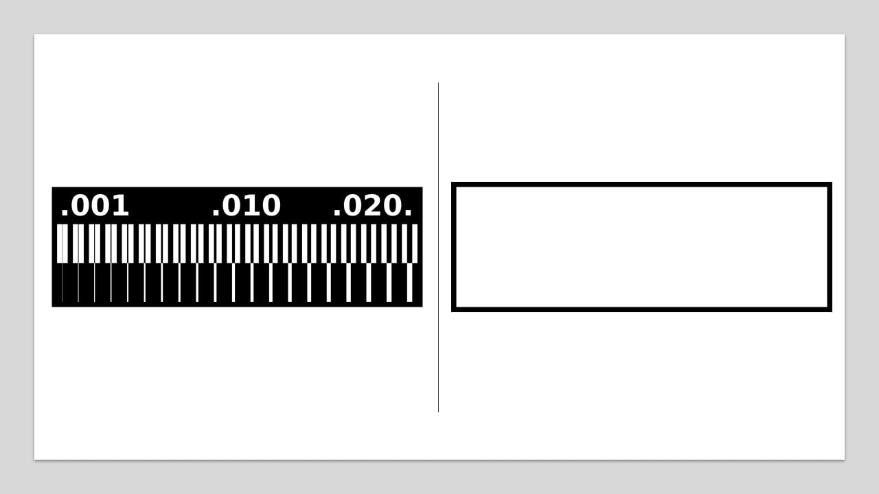
 Outline

Then Proceded with Mods to set up the cutting files I went to Mods,Click Right click to pull up the interface then go to Programs
Then —> Open Local Server
Choose —> Roland SRM-20 –> PCB PNG
After that you will see a set of nodes
what we are going to use is on the left side, click on select PNG and pick the linetest
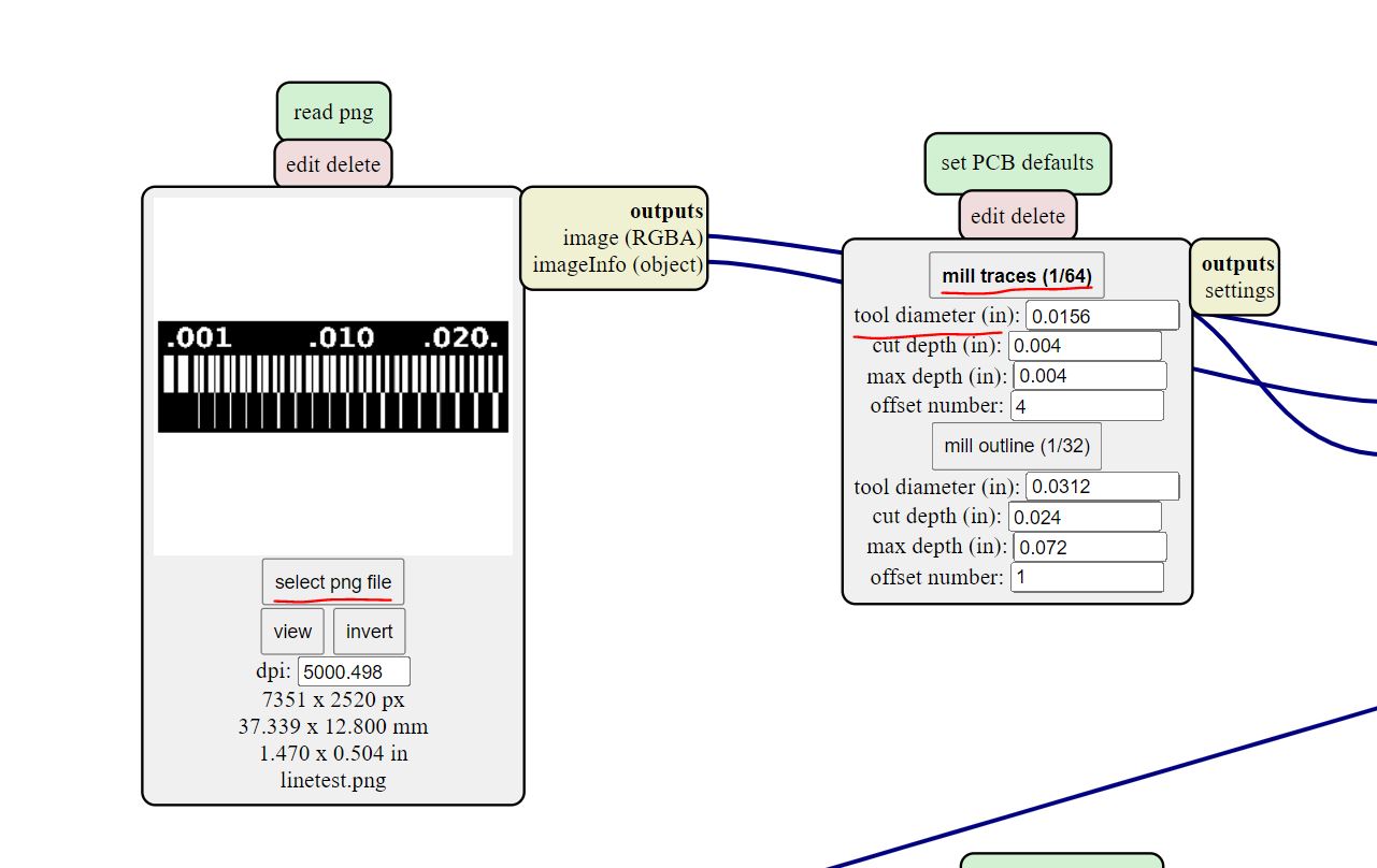
Make sure to change the tool diameter to the one you are going to use in this case 1/64”

Make sure to set the machine coordinates x,y,z to Zero (origin)
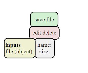
Then to save your file open the menu by clicking right click again and choose —> Programs
Then –> Open server program

–> Modules
Then –> Open server module
Then –> File –> Save
And you will get this Node
And lAST connect the nodes together
After checking everything is ok click we will do the the calculation twice, one for the Climb direction and one for the Conventional direction.
Results
Climb
Conventional