This week focuses on output devices. Output devices can be anything which receives and presents an output of a system. They range from displays, to motors and even printers technically.
Learning:
- Group Assignment
- Power Consumption
- Individual Assignment
- Servo Motor
- PCB Schematic
- PCB Layout
- Mods CAM
- Soldring
- Programming
Group Assignments
Power Consumption
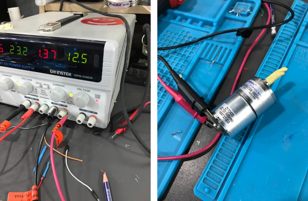
We measured the power consumption of a DC motor using a DC motor output board.
Power (in Watt) is calculated by
Where V is the voltage across the load and I is the current passing through the load.
To measure the volatge and current we used Digital Multimeter (DMM)
- Voltage, the Digital Multimeter (DMM) is connected in Parallel with the load.
- Current, the Digital Multimeter (DMM) is connected in Series with the load.
Remember to move DMM positive test lead to current measuring position before connecting in series with the load.
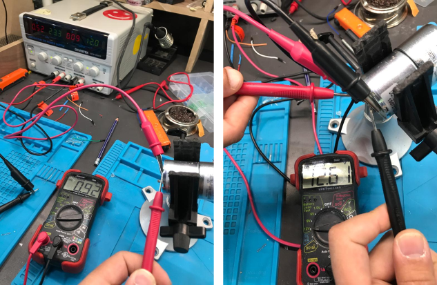
To calculate the power consumption of the DC motor:
Individual Assignments
Servo Motors
In this assignement, I want to design a board similar to the board for the final project, Servo Motors will be the major output devics in my PCB.
A Servo Motors is a rotary actuator or linear actuator that allows for precise control of angular or linear position, velocity and acceleration. It consists of a suitable motor coupled to a sensor for position feedback. It also requires a relatively sophisticated controller, often a dedicated module designed specifically for use with servo motors.
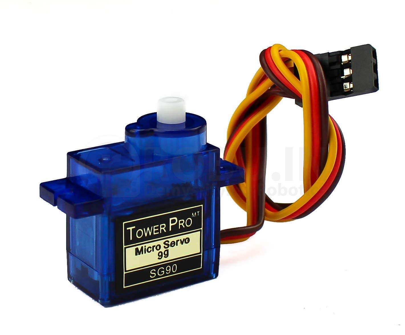
The servos I will be using are 180 degree micro-servos, with just enough torque and angular control capabilities. They are connected by 3 wires (VCC, GND and Signal).
PCB Schematic
The schematics of this PCB is almost the same for the previous PCB at week 6, with a difference in the outputs instead of being LEDs with 2 pins (Data and GND), they became 3 pins (VCC, GND and Data). Also, removed the RESET Button and FTDI pins.
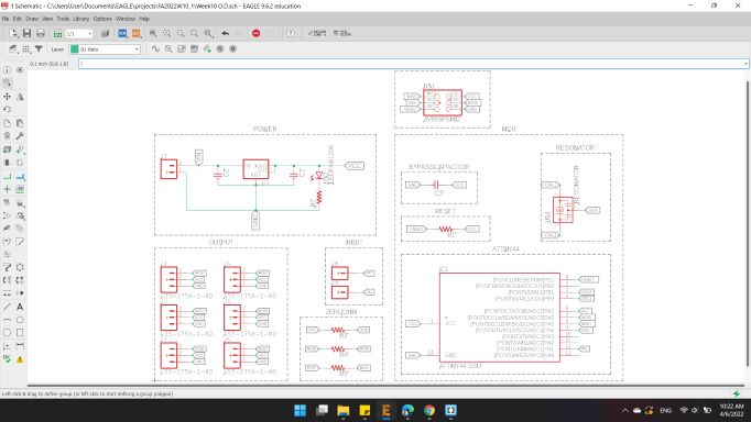
- ATtiny44"ATTINY44-SSU SOIC14"
- Voltage Regulator"V_REG_LM1117SOT223"
- Capacitors"CAP-UNPOLARIZEDFAB"
- Resistors"RES-US1206FAB"
- ISP AVR Male Header 2x3 SMD"AVRISPSMD"
- Male Pin Headers"Conn_03"
- Male Pin Headers"Conn_01"
- LEDs"LEDFAB1206"
- RESONATOR"Resonator"
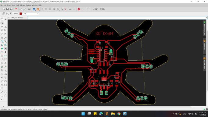
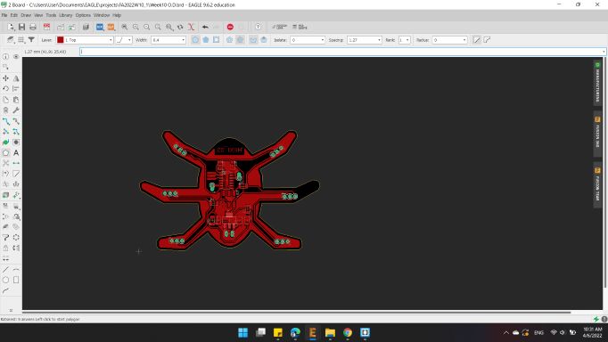
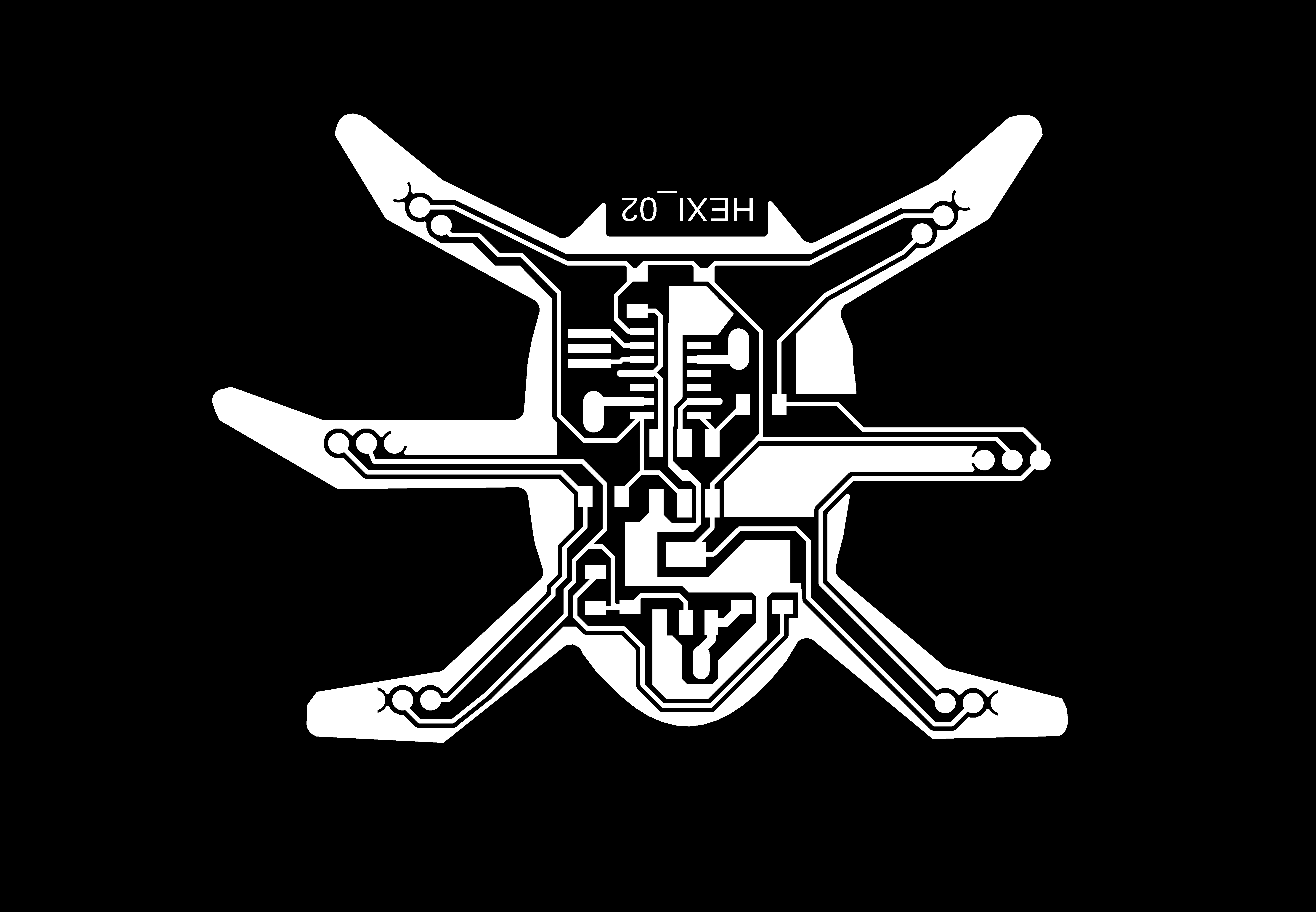
PCB Layout
For the board layout, I distributed the components as before, with the LEDs changed to Pin Headers.
I connected the three servo motors on the right side to the MOSI pin, and the three servo motors on the left side to the MISO pin.
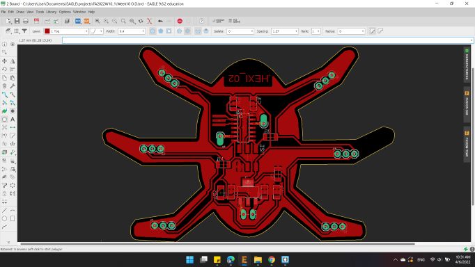
It reached a closed way while the wires were connected to the GND. So, I decided to do a tricky way.

I erased all the GND traces, and then I drew a Polygon from the polygon tools on the left.
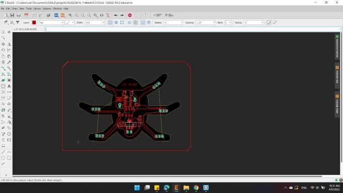
Then name it with GND.
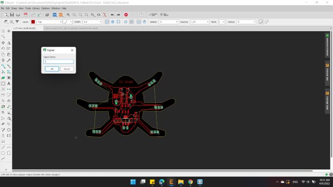
Here's the polygon surrounding the PCB.
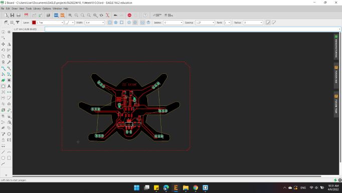
Then, I clicked on Ratsnest, and the board turns on red color, which is a GND connection.
Here's the board with shared GND.
I noticed that there is a wire not connected, I tried hard to find a way to connect it but to no avail, so I decided to connect it with a small wire externally.
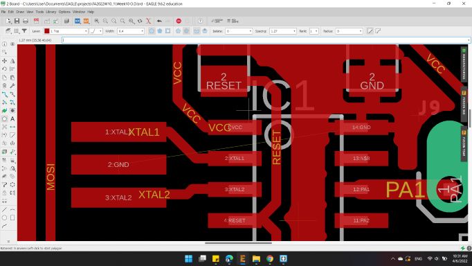
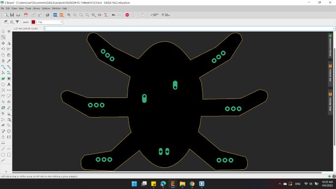
Here's the board, but before exported the images, I wanted to remove the pad and wires names in order to have a clear image with the traces only.
So from Option > Set.
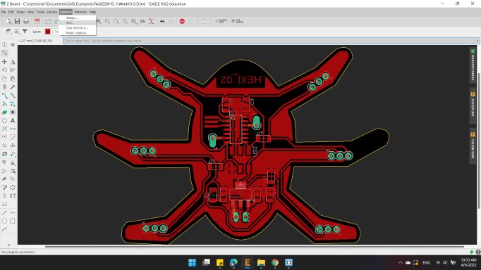
A new window has appeared.
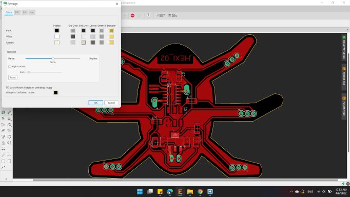
I clicked on MISC.
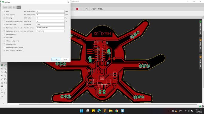
Then turned off all pads and wires name.
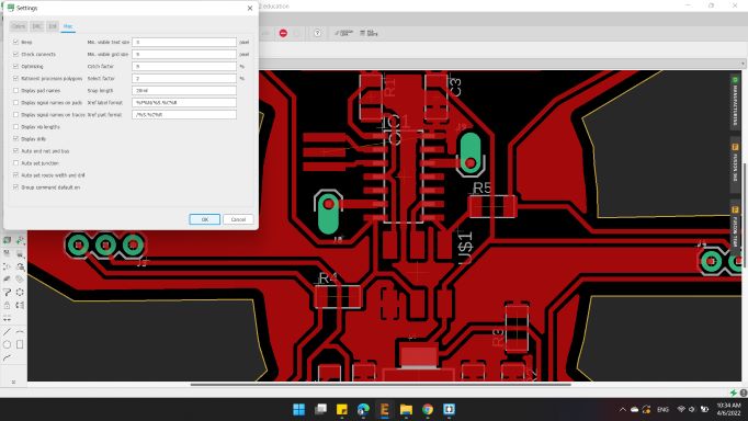
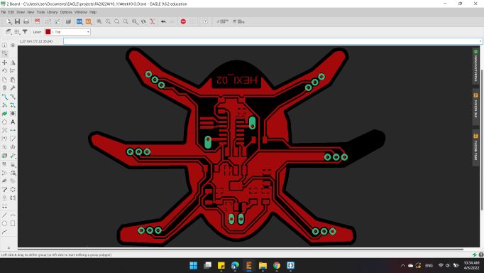
Here's the board ready to be exported.
So, I turned off all layers and kept the Top and Pads, and exported as image.
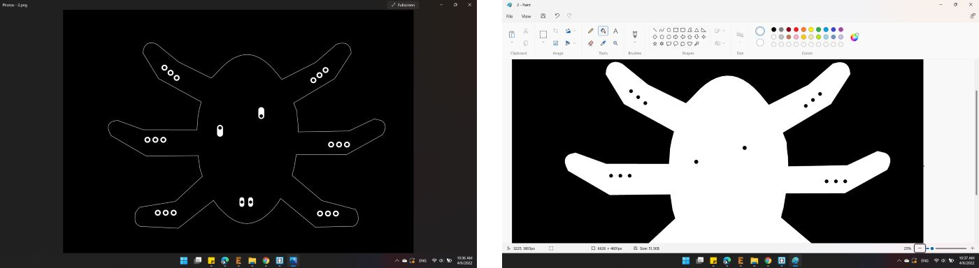
The second image with Dimension and Pads layers.
For the Outline image, I painted the inner area with white color and kept the pads holes in black in order to drill it.
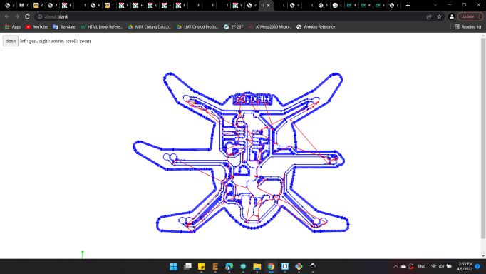
Mods CAM
After the two images are ready, I opened Mods and import the first image Trace, with the same previously options.
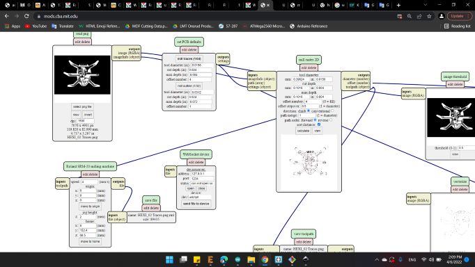
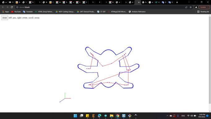
Here's the traces toolpath.
And for the second image, also the same previously options.
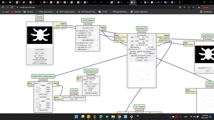
And here's the outline toolpath.
Soldring
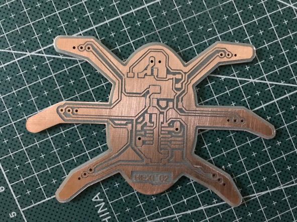
After about an hour, the machine finished making the two images.
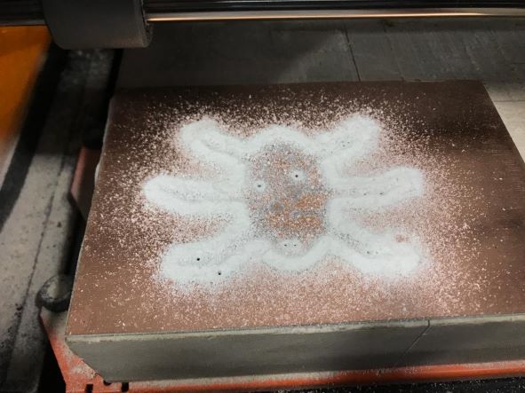
Unfortunately the cutting tool was not clean, I left copper bristles on the traces.
The worst part was that the tool did not cut all the lines 😞
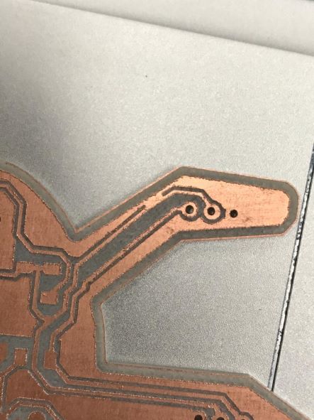
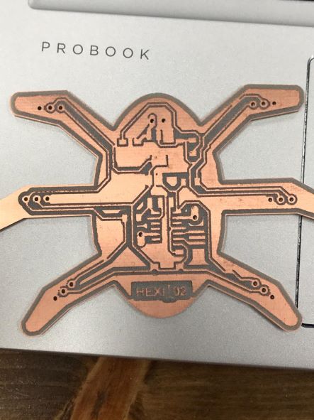
So I decided to use a scalpel and some small tools to cut the lines that isn't cutted.
With the Multimeter, I tested all connections to find a short circuit and the results was good. All lines are good.
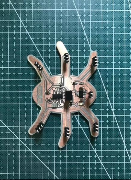
Here's the soldering process 😁
Programming
Final stage is to write the code to run the motor.
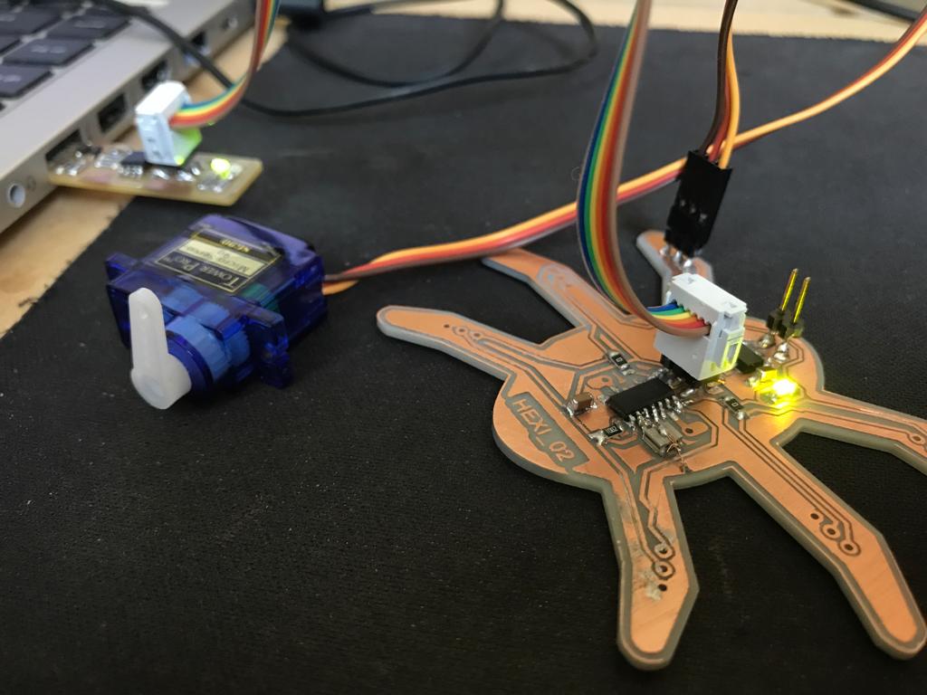
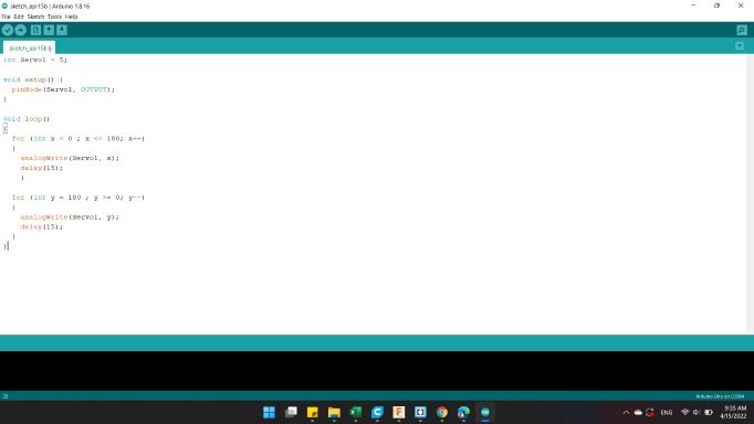
The code I used is below 👇
                        int Servo1 = 5;

                        void setup()
                        {
                          pinMode(Servo1, OUTPUT);
                        }

                        void loop()
                        {
                          for (int x = 0 ; x <= 180; x++)
                          {
                            analogWrite(Servo1, x);
                            delay(15);
                            }

                          for (int y = 180 ; y >= 0; y--)
                          {
                            analogWrite(Servo1, y);
                            delay(15);
                          }
                        }
You can download my files here: