-The Second Group (Karam Khrais, Zayd Khashshan, Suha Al-Habashneh)
CNC Drawing Machine
We at Orange Jo are working on opening a new lab in Irbid. We requested various Digital Fabrication Machines, but there was no digital fabrication machine that could make drawings and with automatic tool change feature.
So we decided to build this machine and it's inspired by the work of HOW TO MECHATRONICS.
To build this machine, it must go through the following steps:
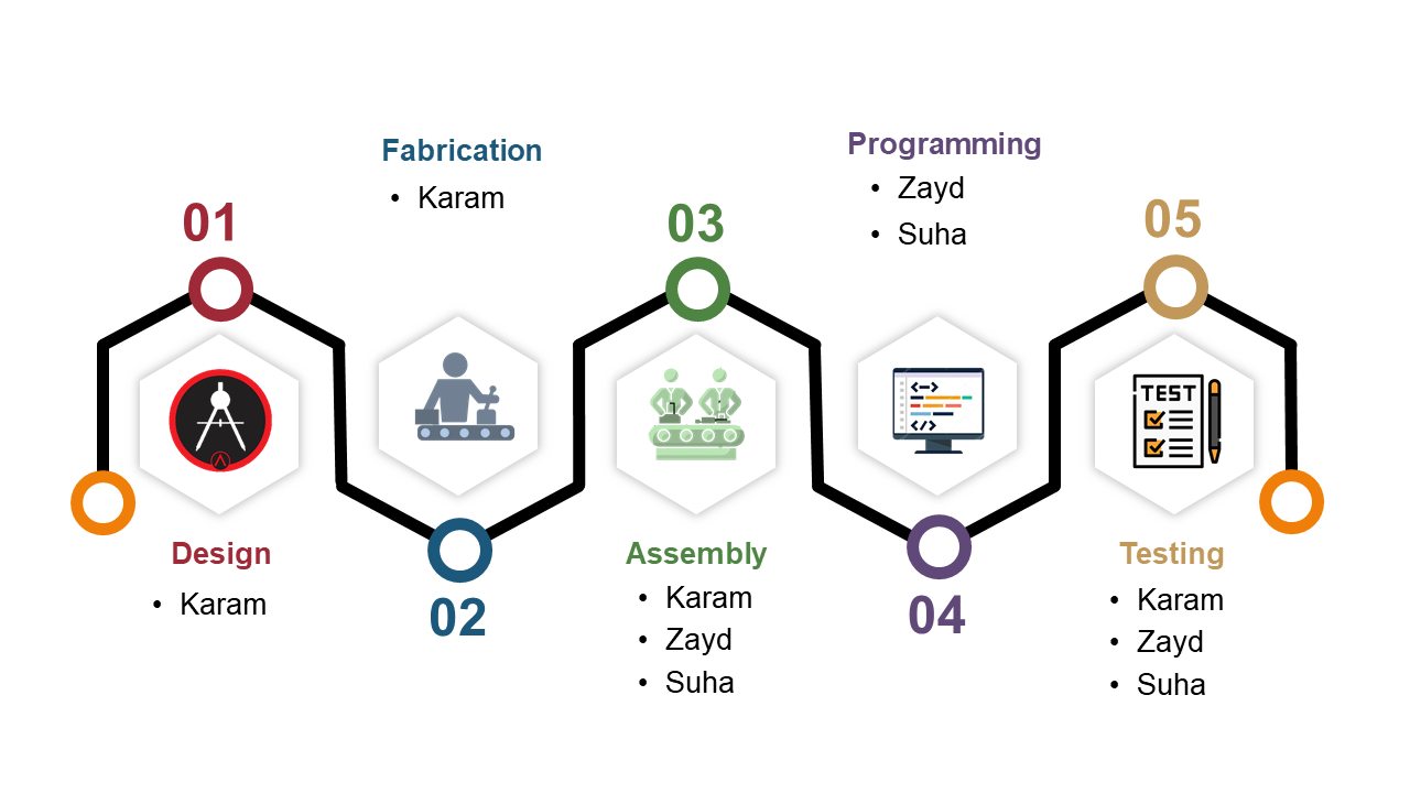
Design, Fabrication, Assembly, Programming
Karam: Design, Fabrication, Assembly
Zayd: Assembly, Programming
Suha: Assembly, Programming
1. The Design
First, before starting the actual drawing, I drew a sketch to identify the main parts, how to move, the position of the pens, and so on.
The most important thought was to make a frame (wall) surrounding the machine, and to support the Y-Axis.
As we mentioned a while ago, the design of the machine was inspired by HOW TO MECHATRONICS, but I made important modifications in movement and shape.
First modification is that the Y-Axis rail is unsupported on one side and the 3D printing PLA material itself is not that rigid, therefore, when the Pen holder head is farther away, the axis is lowered.
So, the modification was to build a front wall that had a track for the Wheel to move onm and lift the axis whenever is fully extend.
Second modification is putting a bottom base to carry and install the whole machine, so that it can be carried easily and gain higher stability.
Third modification is Building a complete frame around the machine, this wall serves to install the machine as required, in addition to its design, it indicates what the machine is, since the machine is a drawing machine,
I built the side wall so that it contains coloring pens,
and the front wall indicates the shapes that can be drawn in various colors.
Finally, I lowered the height of the pen holder, so that the machine is at one height, easy to carry and moving.
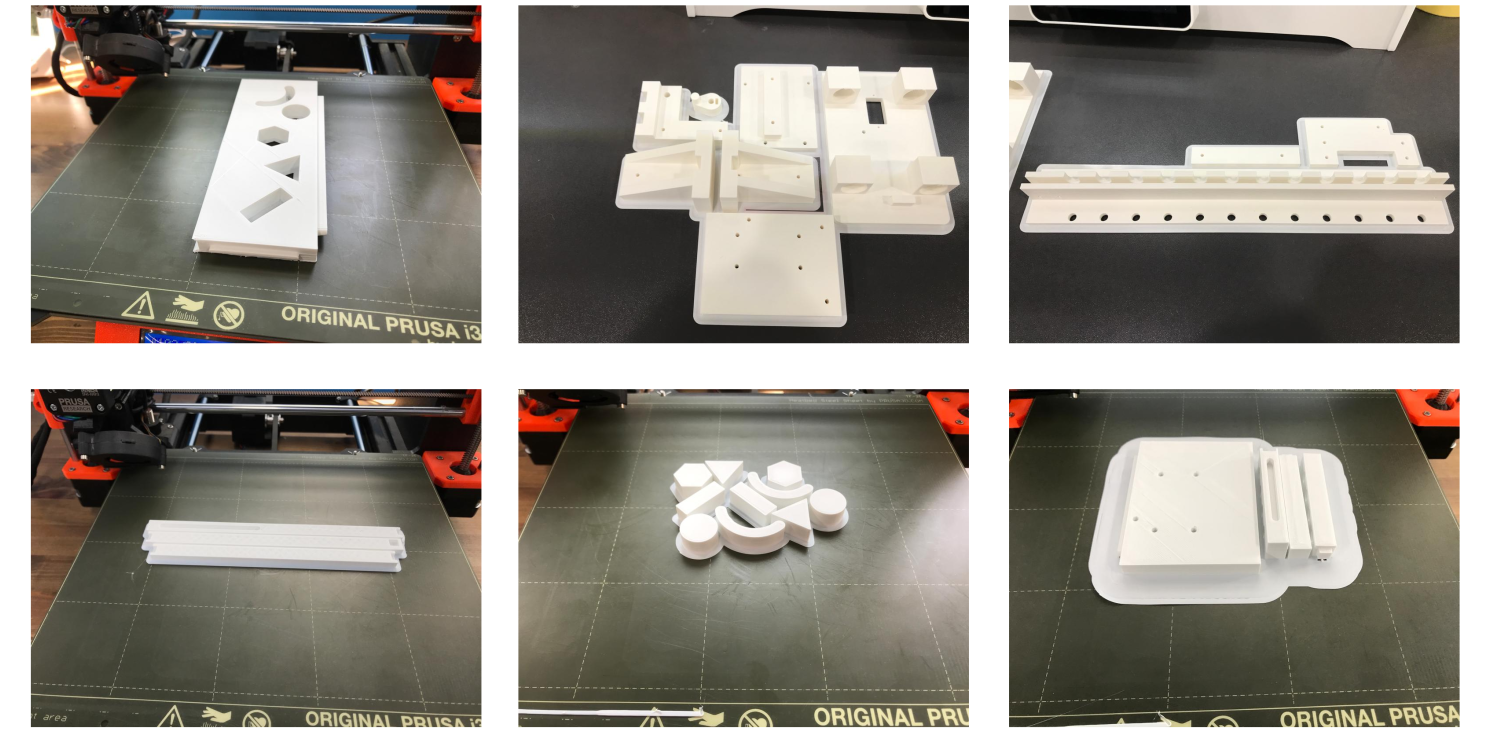
2. Fabrication
Our machine is based on 3D Printing and Laser Cutting machines.
3D Printing
We printed all the pieces in white because there are no PLA colors according to the colors we need.
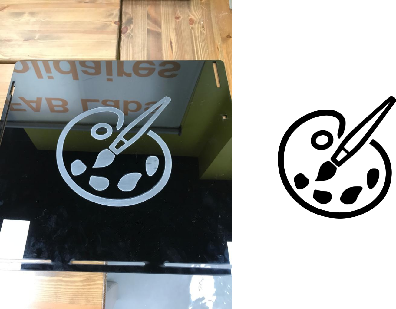
Laser Cutting
We made a simple engraving "Drawing" on the base so that it indicates to the machine as well
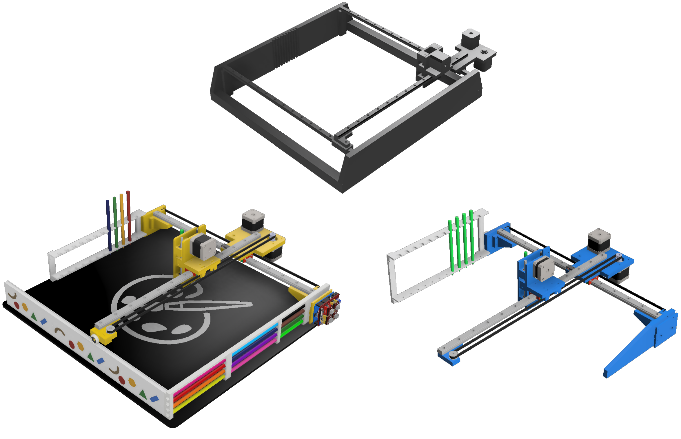
3. Assembly
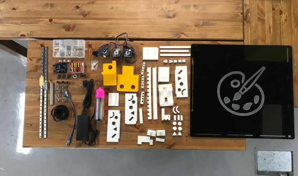
After all the pieces are ready, it's time to assemble!
Bill of Materials
- MGN15 LINEAR RAIL GUIDE WITH MGN15C CARRIAGE L=500MM
- LINEAR AXIS (8 MM DIAMETER) L=120MM
- LM8UU LINEAR BEARING 8X15X24 MM
- STEPPER MOTOR 1.8° PER STEP, 1.7 A, 0.36 N.M ( NEMA17 )
- MINI SERVO MOTOR SG90 9G SERVO (ORIGINAL CHIP)
- A4988 STEPPER MOTOR DRIVER (ORIGINAL)
- GT2 PULLEY 20TOOTH 5MM BORE
- GT2 20 TEETH WHEEL IDLER PULLEY BORE 5MM WITH BEARING
- NYLON PLASTIC WHEEL WITH 625ZZ BEARINGS FOR 3D PRINTER DELTA
- GT2 TIMING BELT WIDTH 6MM RUBBER
- ARDUINO UNO - R3 (ORIGINAL CHIP)
- ARDUINO CNC SHIELD V3
- MICRO NORMALLY OPEN CLOSE LIMIT SWITCH
- ADAPTER 12V 5A POWER SUPPLY AC/DC
- 340PCS M3 (3MM) A2 STAINLESS HEXAGON SCREWS WITH HEX NUTS ASSORTMENT KIT
- FEMALE DC POWER ADAPTER - 2.1MM PLUG TO SCREW TERMINAL
- Color Pens
We started with the Acrylic Base as it's will carry the machine.
With the two X-Axis Rail Brackets on the right and left and the Linear Rail.
Next, the Central Mounting Plate with the two Stepper Motors (X-Axis & Y-Axis) and two GT2 Pulley and two GT2 Idler Pulley.
Next, we installed the right side which contain the 12 coloring.
The Front side with the small Geometric shapes too.
Then, the complicated parts, the Pen Lifter - Fixed Plate with Pen Lifter - Moving Plate and two Linear Axis Linear Bearing and one Z-Axis Stepper Motor and the one Pen Lifter - Stepper Lifter.
Finally, the last parts Pens Holder and Electronics components (Arduino UNO, CNC Shield, Limit Switches, Power Supply and Wires).
4. Programing
For programming of our machine we used 3 programs:
- Arduino IDE
- Universal G-Code sender
- GRBL -Plotter
Arduino program STEPS:
- Download the GRBL library
- Open Arduino IDE
-
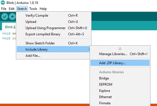
Go to the Sketch → include Library → add Library
-
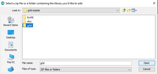
Choose the library of GRBL you have already downloaded
Now the library is added to arduino. -
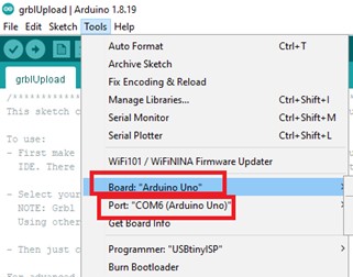
Connect the Arduino uno board and make sure that you choose the right board and the right port of the Arduino board on Arduino IDE software
-
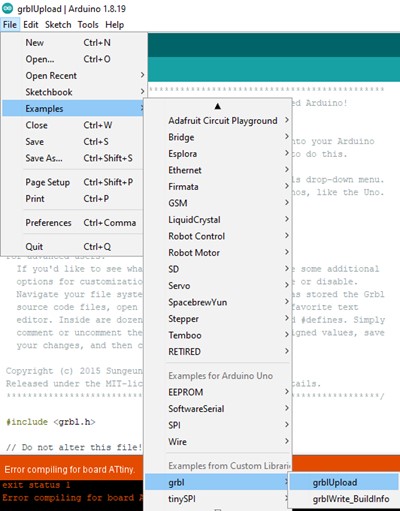
Now, go to file → examples → grbl → grbl Upload
-
Upload the file to the arduino by clicking on upload button
Now we will move to GRBL software to do the calibration of the machine. And then back to it to convert the G-Code we get from GRBL -plotter to the stepper movement.
Universal G-Code sender program STEPS:
- Download the Universal G-Code sender (UGS)
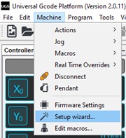
- Open the UGS program and go to “machine” and select “setup wizard”
There are 7 steps here to follow:
-
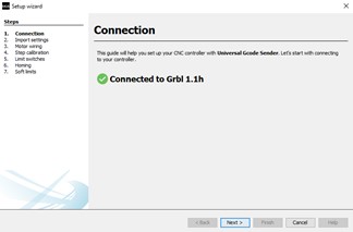
Connection:
Choose the baud rate and make sure it is 115200 , and select the com port that you connect the arduino uno to.
-
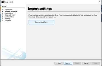
Import settings:
Here we don’t have a pre-settings for our machine so go to the next.
-
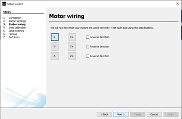
Motor wiring :
Here we assure the positive and negative of our motor steppers if you find the directions reversed, you can modify it by flipping the wires directions or by selecting “Reverse Direction” on wizard.
-
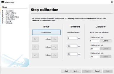
Step calibration:
In this step we calibrate the step with the actual movement on the machine .And by measuring the movement we can find the right value.
-
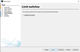
Limit switch:
This is to prevent the machine from moving beyond the physical limits .
-
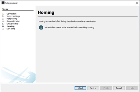
Homing:
To find the absolute machine coordinates.
Now we will move to the GRBL -plotter software which will help us to covert the images to G-Code.
GRBL -Plotter program steps:
- Download the GRBL -Plotter program
-
Open the program , two windows will be opened
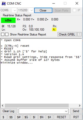
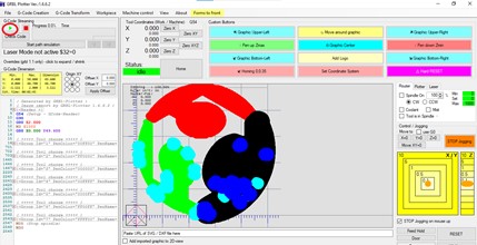
The first one is like below:
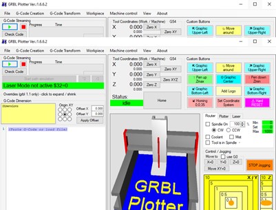
The second one is like below:
-
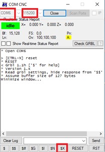
Now open the first window and click on open , and make sure that baud rate is 115200 and the com port name is correct.
-
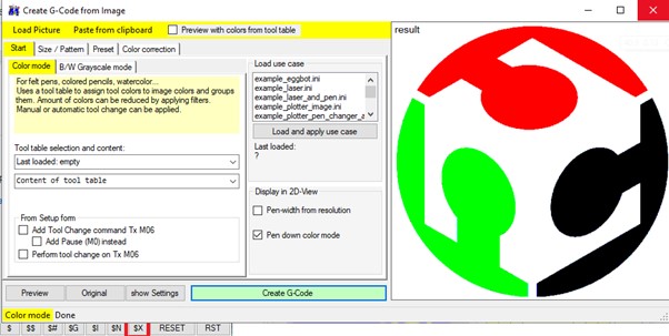
Click on $x then return to the second window and go to the file →open →choose the image you want. Then the following image will appear, click on create G-Code.
-
Now click on “Send code from text editor to grbl”
Files to download: