-
Group work
In the group work we learned toolpath generation, how to attach the stock, how to prepare the machine and how to probe stock.
What to mill?
I've been trying to have higher chamber temperatures in my 3D printer and some of the ABS parts in it have been starting to deform from the heat and stress. This is the reason why I would like to replace all parts with either metal or reprint them out of higher temp materials like PET-CF (€), PET-GF (€), PC-PBT-GF (€€) or PPS-CF (€€€€). I thought that the Z-axis motor mounts would be a simple thing to model and adapt for 3 axis CNC milling.
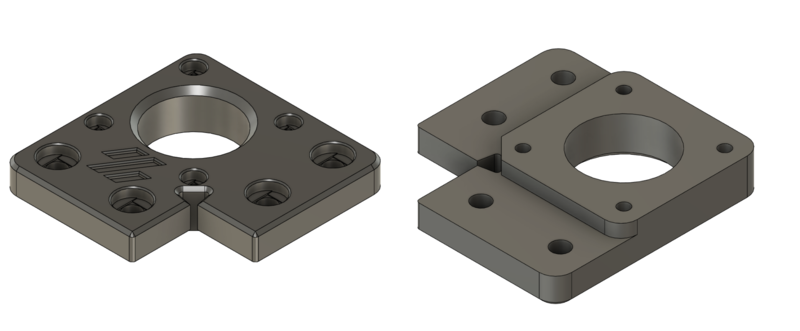
Original part viewed from top and bottom I modelled the part to be machined and decided to try a variable chamfer trick that I had seen. It was a simple way to also add some interesting features to try to select a toolpath strategy. The variable chamfer tutorial was from a Monolith gantry developer called CloacedWayne and it can be found from here.
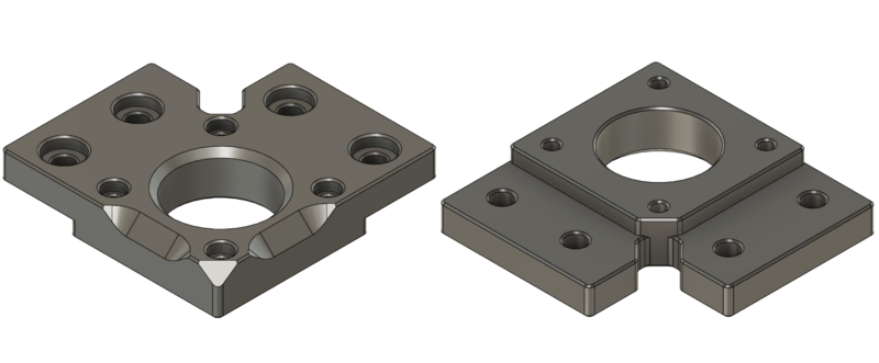
My version viewed from top and bottom Workholding, stock and parallels
I wanted a 3D model of the vise that we have in Haas. This way I could plan the workholding in CAD and maybe avoid some problems. The vise was labelled EVB-35. I searched it for it but couldn't find any info on this exact model. I took some rough measurements and found a one that was almost matching. I made a 3D model based on that and then refined it with more precise measurements I took from the real vise. You can download it from the downloads section but verify the dimensions if you do any critical work.
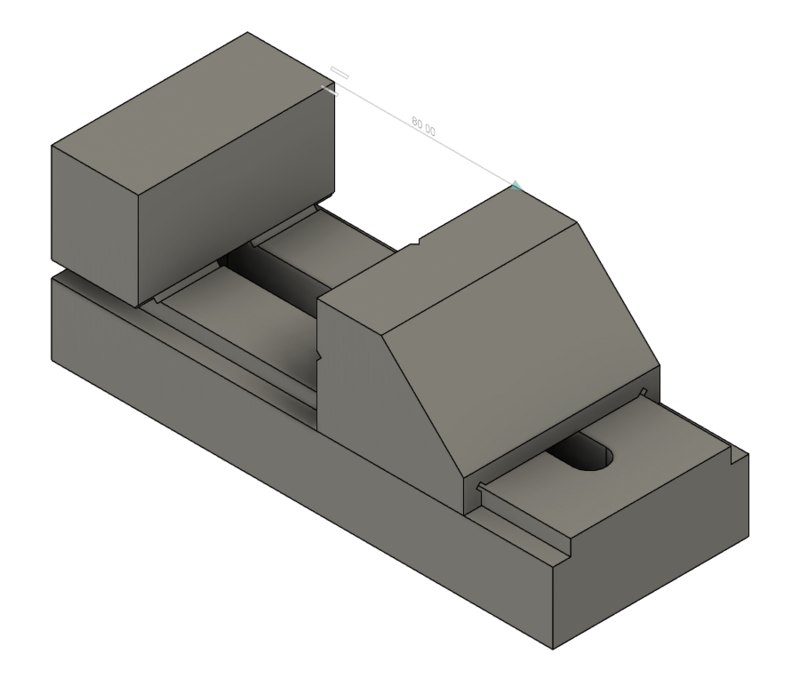
Model of EVB-35 vise As a stock piece I got a piece of aluminium bar that had a hole in it. I modelled the stock also so I could place the part away from the hole in it.
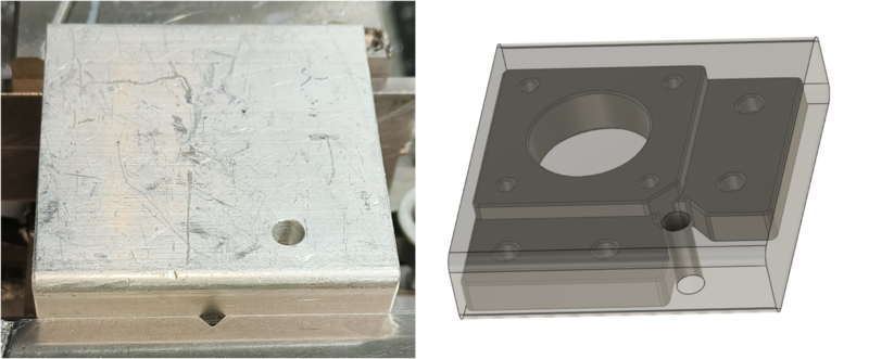
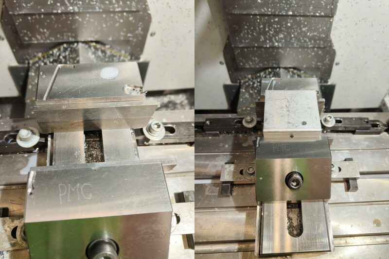
Stock and a model of it with the part inside We only have parallels that I guess the previous machine operators have made in the machine shop. We had 16 mm, 18 mm, 20 mm, 25 mm, 30 mm and 46 mm. With those parallels the best combination, where I could still machine to the depth I needed, was 41 mm and that would have left only 0.5 mm of the flat part to be in the vise. I wasn't comfortable with that so I decided to add an operation to machine cuts that I could use for workholding.
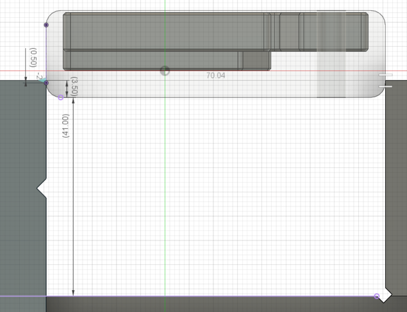
41 mm parallels didn't leave much to grab CAM
I had added separate vise for every operation I had planned to do, so three of them, to the part design. I used constrain to constrain them to the right places. I added the Haas CM-1 as a machine to fusion and added the tool library provided to us. I won't be documenting every toolpath settings because those you can see if you download the source file, but I will document some as an example.
OP 1
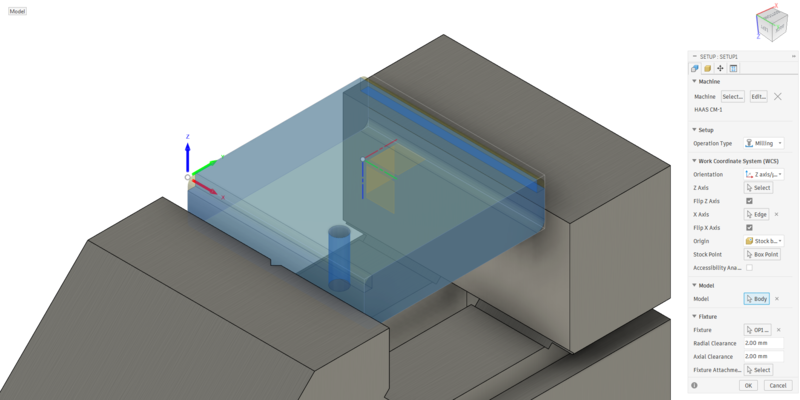
Operation 1 was just two open slots at the edge of the stock. Those were machined so they could be used to grip the part in next operations. In the setup I chose the stock as stock and a modified stock as a part. I selected OP1 vise as a fixture. I placed the origin to the stock corner at top of the stock and left closest corner, if looking in the machine from the door.
Setup 1 For the open slot toolpaths I did roughing, finishing and chamfering operations. I used 8 mm flat end mill for roughing and finishing and 90-degree spot drill for chamfering. Before actually milling I asked some advice on the cutting parameters from engineering students and they said that 0.080 mm feed per tooth, that was from our library, scared them. Sadly, I don't know their names so I can't properly credit the advice but thank you! I lowered the feed per tooth to 0.030 mm that was recommended.
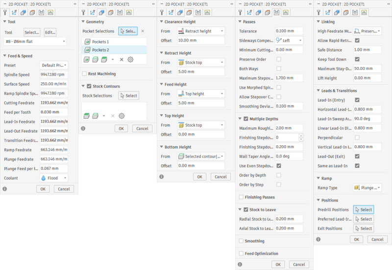
Settings for roughing the open slots For chamfering I had changed the Feed & Speed a bit. I took the values out of other flat end mills. I set the surface speed to 250 m/min and Feed per Tooth to 0.030 mm.
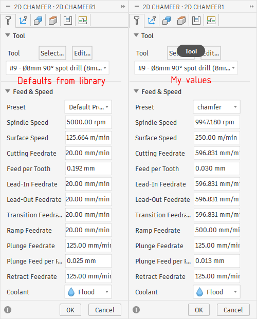
Chamfering feeds and speeds I also remembered seeing or reading a tip to lower the chamfering tool, so it uses the larger radius to cut the chamfer, instead of the more fragile tip. So I set the offset to 3 mm.
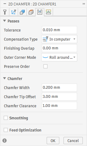
Chamfer offset 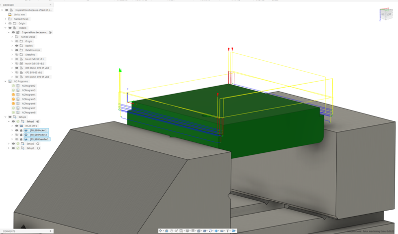
All OP1 toolpaths OP 2
Operation 2 was going to be machining the first side of the wanted part. It was also the more complicated toolpaths. I knew that I had to have facing, roughing for outer contour, drilling, boring and some operations for chamfering. It took a lot of trying and thinking around to come up with the toolpaths and trying to get them in the order that some what would make sense. I ended up starting by facing, then drilling everything, then pocketing and boring, then roughing the outer contour with 7 and 3 mm end mills, then finishing the contour with the 3 mm, then roughing the large chamfer with 6 mm ball nose, and them finishing them with the same ball nose and finally the small chamfers with the spot drill.
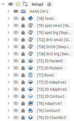
All OP2 toolpaths ![OP2 [T7] 2D Adaptive1](images/SFLM/CNC/OP2T7adaptive1.png)
OP2 [T7] 2D Adaptive1 ![OP2 [T7] 2D Adaptive1](images/SFLM/CNC/OP2T7adaptive1Toolpath.png)
OP2 [T7] 2D Adaptive1 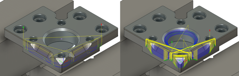
OP2 large chamfers On the first part that I made I didn't extend the regular chamfers at all, and you could see it leaving the part a bit early. So for the second part when selecting the chain to chamfer, I extended the start and end.
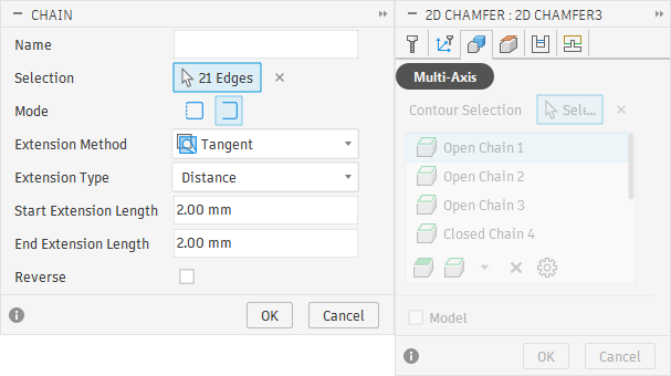
Extending the start and end of chamfers OP 3
For the third operation, I made a sketch with a point right in the center of the bored hole and on level of the machined surface. I did this so I could place the XY origin in the center of the bored through hole and Z to the now bottom of the part. I also set stock as "From preceding setup". For this setup I had to decrease the radial and axial clearances for fixture, otherwise the toolpaths couldn't mill where they needed to. Toolpaths for the third operation were: Facing the extra thickness off, milling the recessed areas with pocket and contour strategies, using flat milling for all the flat surfaces and lastly chamfering.
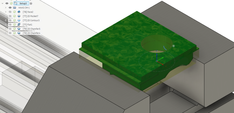
Setup 3 Milling
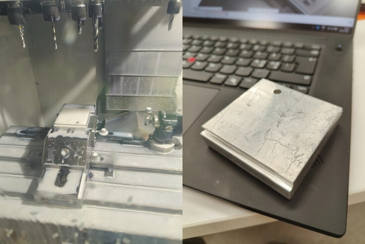
If the machine has been turned off or not used for a certain time, you need to run the 20 minute spindle warm up program before using the machine. The machine was used before me so I didn't need to do that. I picked the parallels that I had planned to use and set them up in the vise making sure there weren't any chips under, or behind them. Then I placed the stock on top of those and tightened the vise.
parallels and stock The next step was to setup the working coordinates. To do this we use a probe that is stored in a separate drawer to keep it clean. To load it to the machine I issued "M6 T20" command, which changes the tool to tool 20, which is an empty spot reserved for the probe, and then held the probe in the spindle. Then I pressed the "Tool Release" button to attach the probe.
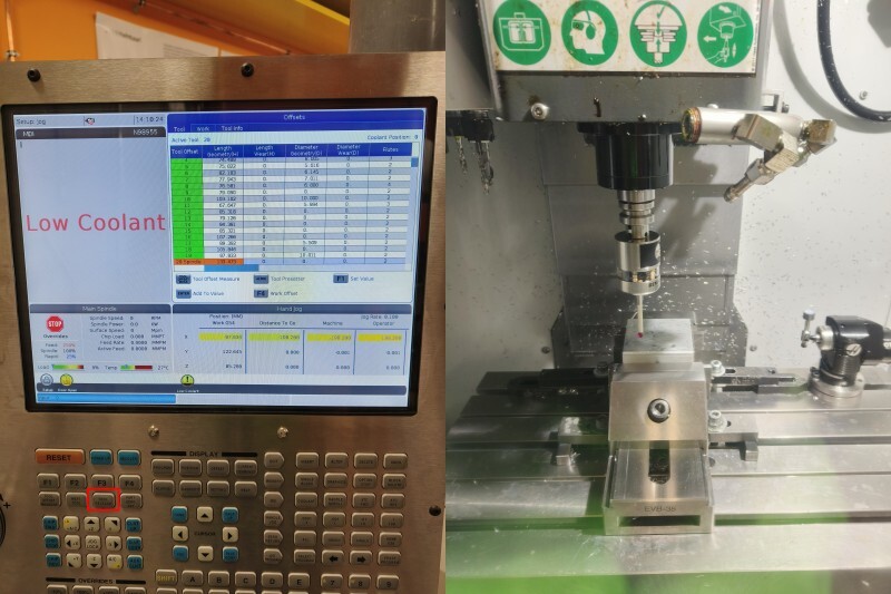
Attaching probe To start to set the work coordinates I pushed the "Handle Jog" button and choose the rate to be ".01". Then I could jog the probe closer to the place where I wanted to probe the Z.
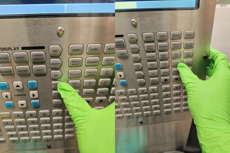
Handle Jog to get close to Z 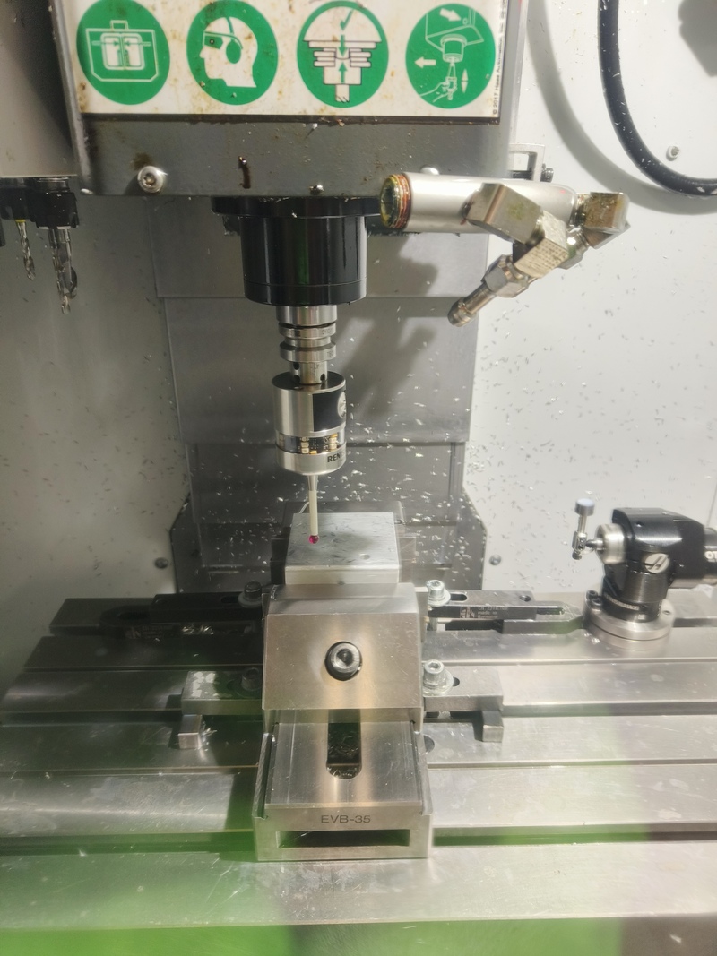
Probe close to the top then I moved to "Work" tab and selected G54 work offset and started probing by pressing F3. From the menu, I selected "Single 'Surface". There I had to select the axis I wanted to probe and enter the distance from the stock. Then hitting "cycle start" executes the probing. This was repeated to the X and Y-axis as well. After probing the probe will be removed with the tool release.
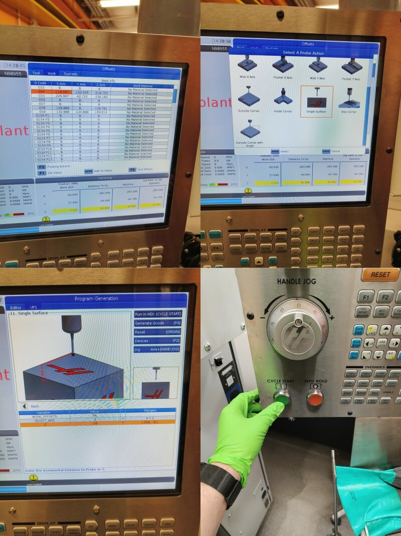
Single surface probing 1 Then I loaded the program by pressing "MDI", followed by "LIST PROGRAM" and finally choosing the correct NC-code and loading it with "SELECT PROG" 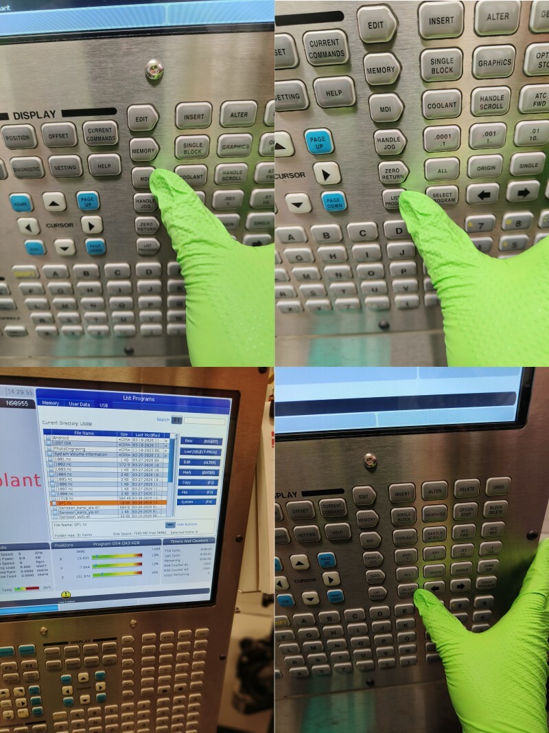
Selecting program After that I reduced the rapid speeds to 25% by using the dedicated button. After that I hit cycle start and the mill started to mill. I was paying close attention so I couldn't take any photos during the milling, but the milling was uneventful and the first operation finished nicely. To end the milling, I cleaned up the chips and then changed tool back to T20 (empty spot reserved for probe) and shut down the machine.
First operation done Operations 2 and 3 were pretty much the same procedure. Only difference was that in the third operation, I used bore probing instead of single surface for X and Y. There I just had to jog the probe inside the bore and set it's diameter as a parameter.
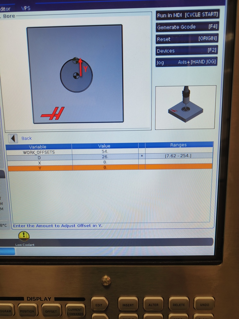
Probing bore I don't remember the last time when I've felt so inspired after learning a new process. So I was really happy with the end results.
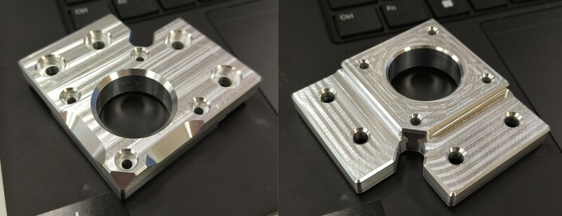
Finished part Downloads
⚠️ Warning ⚠️ I take no responsibility if you crash or otherwise damage something because the vise didn't match the reality EVB-35 Z-mount licensed under GPL-3. The Z-mount is derivative work of the Voron Trident by VoronDesign team.
This work is licensed under CC BY-NC-SA 4.0![]()
![]()
![]()
![]() Unless otherwise noted.
Design by TEMPLATED.
Unless otherwise noted.
Design by TEMPLATED.