The week of mechanical conception and machine design.In this week of Mechanical Design, Machine Design we decided to design a CNC machine. It is a machine that will allow you to mill anything. Example electronic circuit, drawn on wood and cut and everyone contributed to make this.
Working Group
The final work group is here.
INDIVIDUAL WORK
My contribution in this group mission concerns the electronic part.Our machine has three axes. So a stepper motor for each axis. In our lab we have stepper motors with 6 queues. But we don't have drivers to drive them; I searched the market but couldn't find it. The only option I have left, I have to design one for each engine. To build a driver I would use two IC MOTOR DRIVER A4953 to drive each engine. Then that an IC driver has two inputs and two outputs and my stepper motor has 4 bipolar output wires, from where I have to use two A4953
Why did I choose stepper motors in this mission?
Stepper motors are very precise and have several steps, so they are used in CNC machines, robotics and well in areas where precision is paramount...
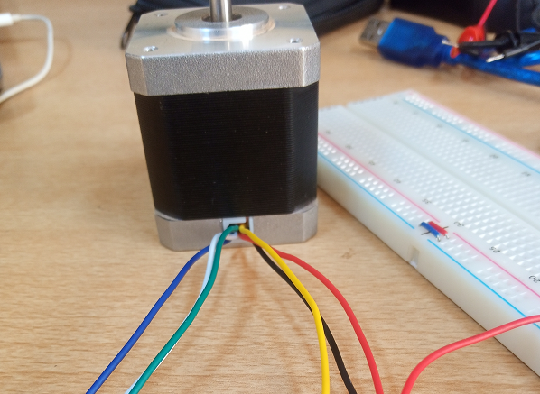
Stepper motors 6 wires
This is a rich this link to understand how the stepper motor works.
At the level of the technical sheet the motor can be supplied with 12V and must not exceed 2A. Here is this link of the datasheet.
I watched more video to understand more about how the engine works. This video allowed me to understand more about the use of the different queues of the engine, in particular the operation of the windings. Here is the YouTube link the link YouTube .
After this video I started by detecting the queues that are of the same winding; to do I used a multimeter and I put in the multimeter function I take a line connected to the other terminal of the multimeter and another line connected to the other terminal of the multimeter, if there is resistance then are wires of the same coil, otherwise they are not; I did like this to detect all the pins of the same winding and put them together, each winding had 3 lines. In my case the first winding has the Black, Green and Yellow lines; and the other Red, Blue, White. Then among these three lines there is a common line in each reel. To recognize it I did the same thing as before but between the three wires of each winding; the line that gives half of the resistance is the common, in my case between black and green the resistance is 62 Ohms and between yellow and green or black it is 31 Ohms. Hence yellow is the common in this winding and white in the other.
After this video I started by detecting the queues that are of the same winding; to do I used a multimeter and I put in the multimeter function I take a line connected to the other terminal of the multimeter and another line connected to the other terminal of the multimeter, if there is resistance then are wires of the same coil, otherwise they are not; I did like this to detect all the pins of the same winding and put them together, each winding had 3 lines. In my case the first winding has the Black, Green and Yellow lines; and the other Red, Blue, White. Then among these three lines there is a common line in each reel. To recognize it I did the same thing as before but between the three wires of each winding; the line that gives half of the resistance is the common, in my case between black and green the resistance is 62 Ohms and between yellow and green or black it is 31 Ohms. Hence yellow is the common in this winding and white in the other.
For the wiring of my motor I used the bipolar option, there we must power both phases at the same time. Torque is important (high).driver design.
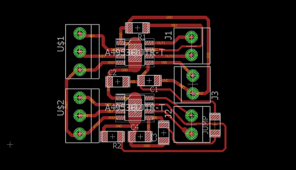
The IC DRIVER A4953 is a component with 2 outputs, 2 inputs, a PWM pin 'VREF', a current controller 'LSS' and vcc and gnd. For a better performance of the component, the designer gave his circuit in the datasheet. I have read and exploited it.
I made the driver's circuit.
EAGLE CIRCUIT A4953
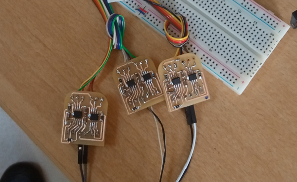
I have finished the welding and I have to test the operation. I checked all the continuity of the circuit, it was good. I plugged in my circuit and wired it with an arduino uno, then uploaded a program to drive the pins; when I measure the output voltages they are not stable. But I still plugged in my motor step by step to reassure me; the A4953 rated power supply is 12V but the IN and VREF pins are connected to the Arduino. Unfortunately the engine makes noise and does not run. It's like braking. But as I already understood the operation of the engine I knew that there are other phases of the engine that are not powered. I looked for the problem, all double-check but idem.
IC DRIVER MOTOR A4953
The driver with the A4953 does not work. I change my strategy. I printed another map using as a driver transsistor mosfet a channel N. 30V 1.7A; but it didn't work too. When I plug in the circuit it heats up. So I decided to focus my efforts on my first circuit.
IC DRIVER MOTOR TRANSISTOR
STEPPER WITH TRANSISTOR
I unplugged my step by step on the circuit of the A4953, then I redid the measurements with the oscilloscope, always wired with arduino and the power supply of 12V. the input signals are good (the IN), but by force of tight and loosen the circuit that connects the VREF of the 1st A4953 is slightly cut, I rewelded it. The output signals of the 1st A4953 are square signal or for the second the signal is zigzag, the voltage is not stable. I judged the component to be faulty and replaced it. I checked but everything is super nickel. I plug in my stepper motor and its works wonderfully. The question I ask myself is how can a new component fail? so I fixed the other two drivers.I uploaded some code to the Arduino to see how the motors work, and everything works as expected.
The drivers work, let's move on to the software side. We need to download a firmware for arduino uno that will allow us to control our engines step by step. This firmware is the GRBL firmware. I downloaded the ZIP file in GitHub via the link. I need to upload this program to the arduino board.
I unzipped the file and then opened the Arduino IDE software. In tool, I click include library then I look for the file unzip grbl and I click on it, I click again on the file grbl and then open. On the Arduino IDE in fileexample at the bottom, there is the grbl file and open. It is a program with only one instruction, but do not worry, the work is done in the background with the library. Finally choose the Arduino port of your card and upload the program.
The Arduino is ready to be used as a CNC machine as it can read the G-Code by driving the different stepper motors. Now I have to tell the Arduino what to do; which is like driving the machine with the computer and for that I have to install software that will generate G-Code. This software is the Universal G-code Sender.
This software is under java, to run it you must first install the JAVA Runtime Environnent software . I downloaded it and I unzipped the java file and then in bin I ran the java application. Then in the bin folder of Universal G-code Sender (UGS) I ran the file "ugsplatfrom"; then I plugged in my arduino board and on the UGS interface I put the baud number at 115200, then select the port of the arduino board and click on connect. The board is connected with the SKU software. I can drive my engines via the Arduino. But a real problem that puts a brake on my work; I don't have the Arduino CNC Shield, and no A4988 driver. With this the application becomes easier. I plugged all my files into the arduino ports and I open the grbl folder, I open the file 'cpu.map', this is where the pins are declared. I tried to modify it to adapt my drivers that I designed, I saw that it declaquer two pins (DIR and STEP) per driver. But mine is worth four, in addition I have to adapt to all the other files, which becomes even more stupid. I'll take a look at the technical sheet of the Shield CNC that was also confusing. We looked for the Shield and the drivers on the market but we didn't get it. I'm lucky, I had an A4988 Driver in my possession. I will manage to drive a single axis.