GROUP WORK
INDIVIDUAL WORK
This week of the 11th I will make a circuit that will control two three DC motors plus a solenoid valve. This system will be used to feed chickens (Farm Box).
The design procedure of my farm box.
Design my electronic circuit to control DC motor
Welding of components;
The programming of the circuit with Arduino;
Design my electronic circuit so the MCU is an ATtiny45 via the eagle software.
I open my eagle software, and I open my file of the week of 07; so I will edit this file by adding three spell ports. I will add an IC motor driver 8V_40V to my circuit; I must study this component well before integrating it into my circuit. I did some research on the component. I downloaded the component's datasheet and tried to figure it out. I understood how this component works. At first when I saw these 8pins I said that I could connect all three my motors to them; but after reading the datasheet of the component I can only connect one motor. Ha too bad, so to accomplish my mission I have to use three components too. The technical sheet of the component is as follows this link .
Designer Circuit
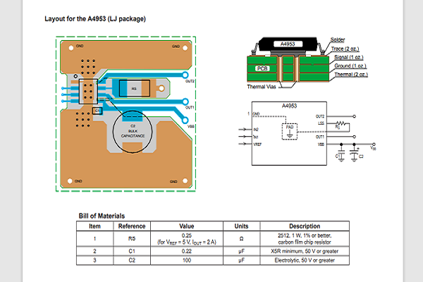
Detection pin (LSS). In order to use PWM current control, a low value resistor is placed between the LSS pin and the ground for current detection purposes.What I'm going to do is make an individual circuit for this component on its own, and then test it with arduino. If I happened not to have made a mistake then I would make a circuit with attiny 45.
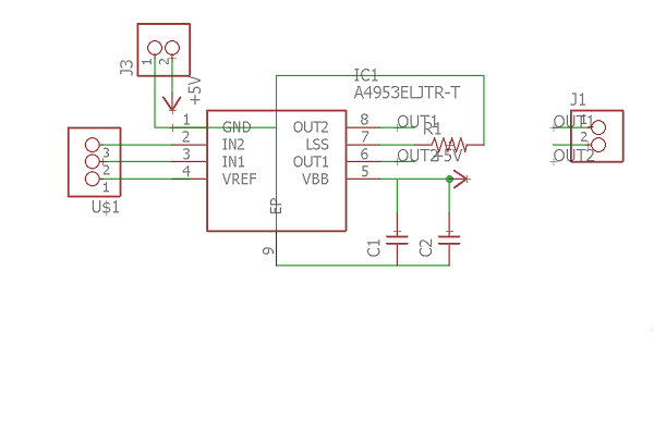
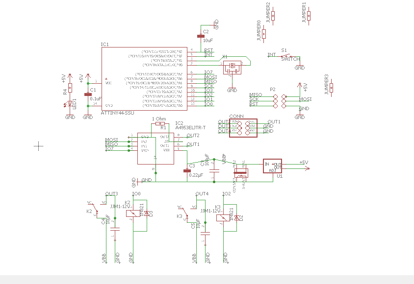
For to do, I downloaded the Librairy eagle of the component on this site, this link.. But the part of the datasheet that interested me is the following. Then I extracted it and exported it to the librairy eagle. I drew my circuit as described in the component data sheet. I finished designing the circuit and exporting to my USB stick;
Schema of circuit in eagle
Trace Circuit
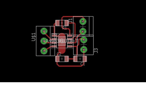
Now I will mill my card on the machine modela mdx-50.je part on the computer of the machine I plug my USB key, and I open suck; then I import the image of my circuit. I do the bitmap and use the guides to position my circuit. After the positioning at the coordinate 112mm, 84mm I click on toolpath to generate the trace of my wick. I chose the engraving function, the engraving thickness is 0.16mm; the wick used is 1/64inch or 0.38mm in diameter. The deep pass is 0.5mm, the stepover is 0.6 so 40%, the splindle speed is 12500rpm; the Feed Rate is 30mm/s and the Plunge Rate is 15mm/s. the engraving type is Offset Climb. And then calculate; when I zoomed in on the plot there were pins touching, so I decreased the diameter of the wick to 0.32mm in the settings and recalculated. Now it's okay.
The change of the modela wick is automatic, so on the screen of the machine I click on tool1 and the machine automatically deposits the wick that was there in its collection in the tool holder 3 and takes that of 1/64inch in the tool holder 1.
After changing the wick, I opened the Vpanel driver software of the modela machine and clicked on Cut, I delete the current file and add my file save via aspire and open, output; the engraving took 5min. but it was not good, I do not know if it is because of the cutting speed or the stepover there was a lot of burr on it. I used the cutter to scrape as Mr Neil says but the tracks of my circuit have cut. I restarted another cut by changing by improving my circuit; in fact I have spread the lines between them. Then I changed the settings. I reduced the engraving thickness to 0.15mm and put the wick diameter back to 0.38mm. Then the deep pass is 0.2mm, the stepover is 0.133 so 35%, the splindle speed is 12500rpm; the Feed Rate is 20mm/s and the Plunge Rate is 10mm/s. the engraving type is Conventional Offset. I calculated saved and then relaunched; the engraving took 6min and it was really great as the other. No burr or contact between the pins.
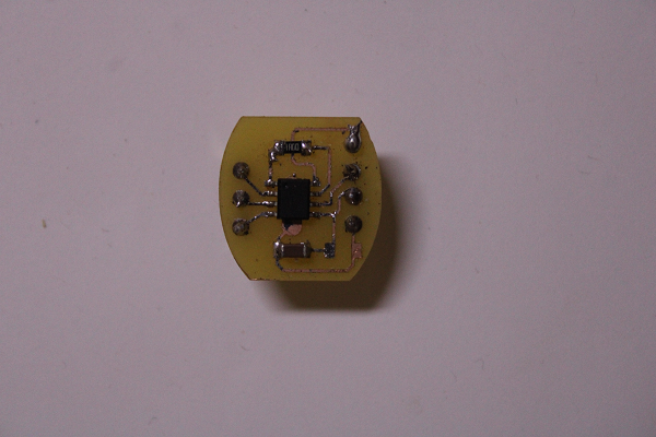
Welding as usual I set my welding station to 280° degrees. The welding was perfect.
Circuit Welded
The first test of my circuit, I first welded my assembler on the OUTPUT1 and OUT1 output pins of my component. Then I plugged into the GwINSTEK oscilloscope to power my circuit through the VBB and GND pins, set the voltage to 10V, then I set the voltage of the other to 5V to power the IN1 and IN2. When I plug in his does not give. I forgot to plug the two GNDs together. I did it and its give. My engine works wonderfully. I tested the braking of the circuit that he talked about in the spec sheet. It was necessary to connect the two IN1, IN2 to 5V simultaneously its answers correctly; it's a real brake no short circuit.
Now I will use arduino to order my circuit. I will test a program then I will redo the circuit with an attiiny45.with arduino I tested the PWM. To do this I connected the two pins IN1 and IN2 to pins 5 and 6; then I opened the blink program, and modified by declaring pins 5 and 6 as output; then I copied the program into the void loop to duplicate in order to have both outputs. Then I uploaded the program and its work well; I added the braking by putting both 5 and 6 in HIGH. Braking has me much more, how the engine stops abruptly even at the speed it has. Afterwards I had to test the PWM; in example on the ide arduino I opened the file Fade, then I erased in the declaration of the led which is connected to pin 9 and replace by pin 5; for PWM (Pulse Width Modulation). I uploaded the code. Its walk cleanly. But when I plug in the VREF pin the motor stops working. In the technical sheet of the component it is said that to control the speed one can use the VREF pin; so I used it by plugging into port 3 of my arduino; now instead of driving my pin 5 as PWM I rather drive pin 3. Pin 5 I put it at HIGH only. The test was good and I measured the voltage at the terminals of the motor and it degraded according to the PWM from 0V to 10V.
Manuel control motor
I tested the LSS pin of the component, in my lab I do not have a RES of 0.25 Ohm as said in the datasheet; this resistor is to control the motor current for the PWM; so I used a resistor of 1 Ohm. It worked with PWM; then I changed the resistance to 0 Ohm; the engine certainly runs but the PWM does not work, that is to say no speed degradation or anything, it is as if you have connected the motor directly with the power supply. Then I handed over another 4.99 Ohm, it was the same result. So I re-welded my resistance by 1 Ohm. Subsequently in my next circuit I will decrease the resistance by putting two resistors of 1 Ohm in bypass.
Movie with arduino
When I plug in the circuit, at start-up the engine makes noise, to solve this problem I asked coach Abu, he told me that I can use a filter, and the filter is composed of a diode in series with one of the pins of the motor and an electrolytic capacitor in bypass with the motor. I did not have the diode on site, so I used a capacitor of 1μF plug as indicated; but I turn on the circuit my oscilloscope detects a short circuit and the motor stops, currently I am at 10V; then I used another 10μF condo but it was even a result; so I reduced the supply voltage to 8V then I reconnected the condo of 1μF, it works but the speed of my motor is downright reduced, I changed with that of 10μF and it was the same. In addition to its my IC is except more advantage. I tell myself that with this component we would not need a filter. But nevertheless I will redo the circuit taking into account the filter.
Movie with capacitor
Designing my electronic circuit so the MCU is an ATtiny44 via eagle software; In the near future I have a project that requires two motors and a pump. So I will do a taste test in order to improve it if there is error. To power one of the motors and the pump I connect them from a 12v relay and the other motor is controlled with the A4953, because I want to use its PWM to vary the speed.
Circuit design on eagle software. I took the electronic design week 7 circuit to modify. I added ports 13 (PA0), 11 (PA2) to control the two relays, then pins 6 (PA7), 8 (PA5), 7 (PA6) wired with the A4953 to control the other motor.
Schematic
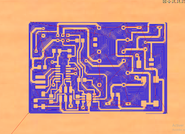
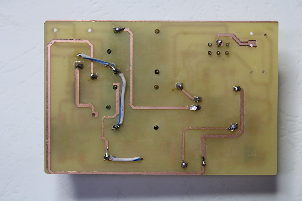
During the modification there was a lot of tracing, so I couldn't do all the roads without their pasts on them, and that would cause a short circuit, that's why Coach Abu told me that I can do on a double-sided PCB; I'm so scared because it's something I've never done. But this is an experience for me. On my circuit I used the color red to draw the lines of the first surface and the color blue for the lines of the second surface (surface below). Then to connect these two surfaces I made holes that connect the two surfaces. Now I record my circuit. To record the circuit of the first surface I uncheck all the colors except the red and the green (pads) and dimension (the red represents the layouts of the circuit, the green are the holes);
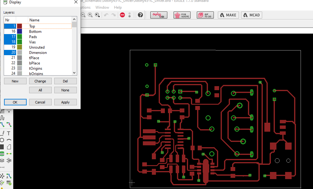
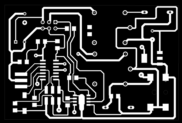
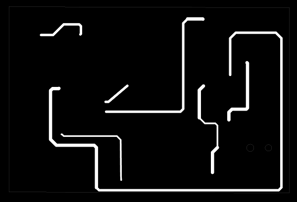
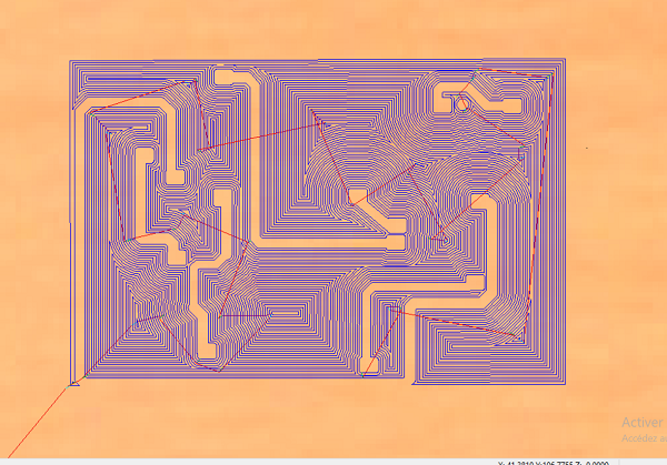
For the circuit of the second surface it is blue, and the holes to join the two circuits are green (vias). I do the same for the first. I save all as a png image.

After having finished with the circuit I save the images on my USB key, then on aspire, I first import the first circuit. I create the route of the wick by clicking on toolpath, I click on engraving, then I choose the thickness of engraving which is 0.15mm. I chose the end mill wick 1/64inch or 0.38mm in diameter. Then I chose Deep pass is 0.5mm, stepover is 40%, splindle speed is 12500rpm; the Feed Rate is 30mm/s and the Plunge Rate is 15mm/s. The type of engraving is Conventional Offset finally calculated, there are parts of the circuit which touch, at the level of attiny44 the pins are very small which leads to this. To remedy this problem I will go back to the diagram, I ungroup the circuit. The part that touches I modified their lines using the sketch commands of aspire and finally calculate. This time it's good. So I save my first aspire file from the first surface.
Trace Circuit
Trace Circuit
To start the milling of the first circuit I first selected all the holes of the circuit then the holes with an end mill 1/32 bit. In the parameters I chose a thickness of 1.6mm (thickness of the card), the deep pass has 0.8mm, the stepover has 35%, the splindle speed has 12000rpm; the Feed Rate at 20mm/s and the Plunge Rate at 5mm/s. Machine vectors Inside/Left climb and the number of passes is 2. Done for 2min.
Because of the second circuit of the second surface, I will put four holes as marks. I will first drill the 4 holes 20mm deep and drill them with the profile toolpath function; I used a 1/8inch end mill bit. In parameters I used: I chose The deep pass at 1mm, the stepover at 35%, the splindle speed at 12000rpm; the Feed Rate at 20mm/s and the Plunge Rate at 5mm/s. Then launched the drilling, it lasted 1 minute. Then I have to put wedges in the drilled holes to serve as a guide, I used screws; but these were long, so I cut the heads of the screws in a vice (workshop).
I fixed all of them and started milling the first circuit, it took me 36 minutes.
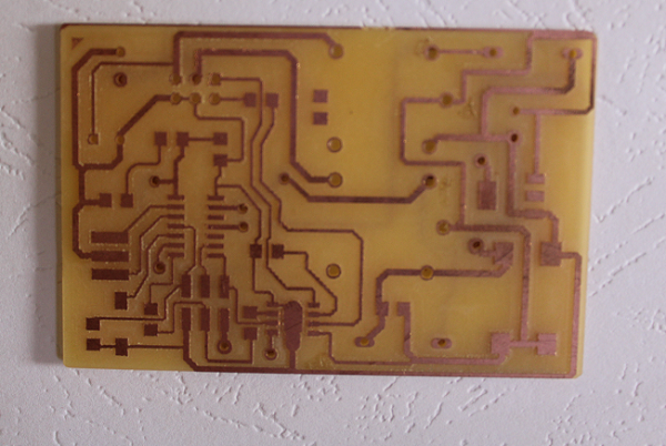
Now the second circuit. To achieve it it must be very consistent with the first. I placed it on the first circuit, and do Mirror. I did Mirror then I have to reverse the PCB and use the guides to put it back. Still on aspire I will mirror the circuit then in toolpath parameters I still chose engraving, I chose the thickness of engraving which is 0.15mm. I chose the end mill wick 1/64inch or 0.38mm in diameter. Then I chose Deep pass is 0.5mm, stepover is 40%, splindle speed is 12500rpm; the Feed Rate is 30mm/s and the Plunge Rate is 15mm/s. The engraving type is Conventional Offset; Finished the milling which took me about 20min.
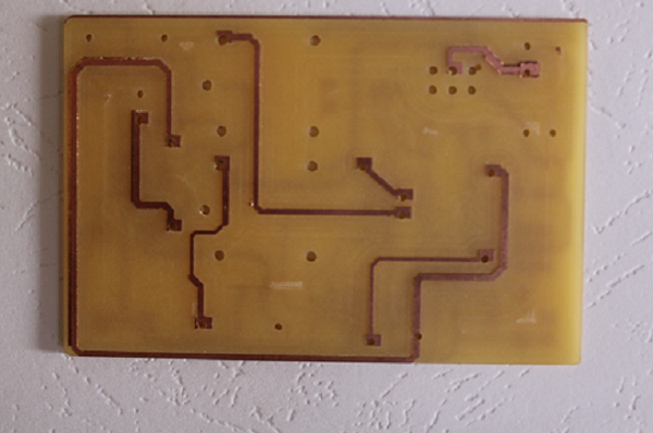
The second circuit is not fully aligned with the first. But that doesn't hurt. Only next time I have to widen the width of the tracks of the second circuit
Component soldering. The welding station is set at 290°, the suction fan is on. Some components like the two relays are not available in the lab. But I recovered them on scrap plates. Soldering did not take enough time or difficulty. I miss components like capacitors and diodes, so I couldn't put them. But this does not prevent the operation of the circuit.
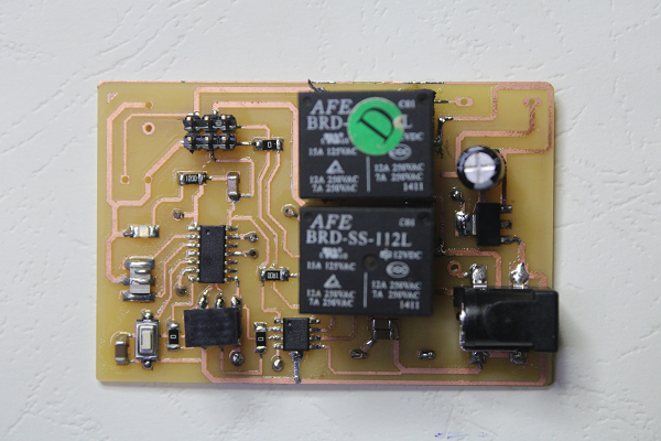
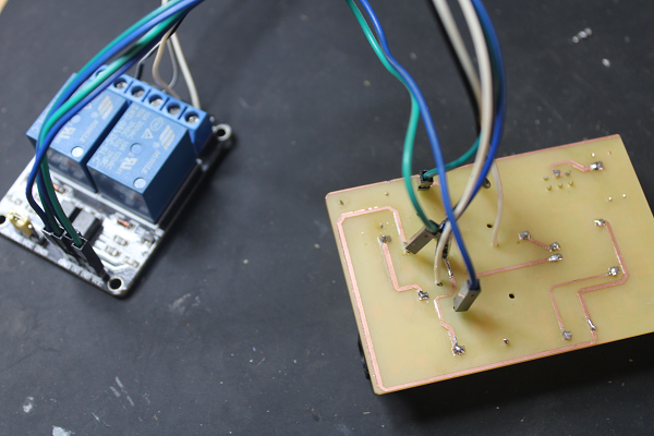
There was something unexpected so I used independent threads. I thought my relays could be powered with 5V, but when I plugged it in it was only 8V that could make it move. That's why I connected the 12V wire to each of them. This was DIY.
All welds are good. For the moment there is no problem.
I connected my circuit but the relay the two relays did not respond; I had made a small program Just to test the relays. Alas it did not work; in addition the charge regulator heats up a lot, I tell myself that I have not correctly sized my filter capacitor; then I put a 100µF capacitor at the 12v input of the 5V regulator. but I had plugged in 12V; ok short; I recovered the missing components on a faulty board.
To remedy my relay problem, that's when I changed them with an industrial relay that I had in my possession. I unsoldered the two previously soldered relays, brought out the soldered wires and connected them to the industrial relays.
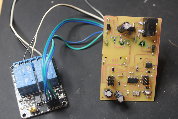
I reconnected but one of the relays does not respond. So I used the other for the rest of the operations. Then the same program to also test my IC A4953. that too was faulty. When I measure its output with the oscilloscope, the signal is zig zag. Is not stable. I changed components. The signal is now stable. Since the regulator saves a lot, I therefore removed the 3 electrolytic capacitors that I had soldered. After this action the percentage of heating to decrease by 40%; in short, I really don't know why this is always excepted.
Let's move on to programming. Having custom, I will use arduino to upload my code in my circuit. The first program aims to control a motor by controlling its rotational speed.
PWM Control
Everything is fine, but I'm going to make another program to drive the motor in two directions and play with the rotation speed too.
TWO DIRECTIONS
Finally this code is to drive the motor in two directions. In reality I should put limit sensors to stop the engine but soon. And the other motor will be driver through the relay.