 Home
Home
Input DevicesRecaps and Task Outlines April 20th, 2022, the course continued talking about:
The objective of weekly assignment are:
Learning Outcomes After this course, I am able to
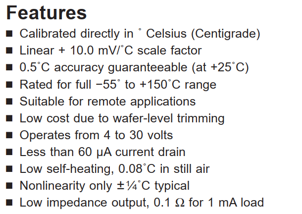
Add some sensors to already designed board Group AssignmentIn this group assignment, we did probing on analog and digital sensor as can be seen here. What is a sensor?According to Wikipedia, a sensor is a device, module, machine, or subsystem that detects events or changes in its environment and sends the information to other electronics, frequently a computer processor. Sensors are always used with other electronics. Analog SensorThe definitionSimply put, analog sensor is devices that can sense physical object and give analog output, most likely in volt unit. The output will range from 0 v - VCC, if you are using VCC = 5 V, then it is 0 - 5 V. Nowadays, a microcontroller is equipped with a device called Analogue to Digital Converter (ADC) to automatically enable the microcontroller translating value(s) sensed by the analog sensor. It is important because digital device can not understand directly analog value. The realisation of ADC in a microcontroller is in specific pin assignment. Some microcontroller also provides voltage reference that can higher up the higher limit of ADC reference voltage in the process of digitalisation. So, even if the sensor we use is analog, it will be digital at the end prior to processing in the microcontroller. ExamplesThere are a lot of analog sensor available in the market. They can measure one entity but with different precision and, of course, price. Sensor with high precision is pricey, but having cheap sensor does not mean it is far from precise. It just, sometime, not robust to noise that make the read out fluctuates often. That is why, to cope the problem, we can add post processing to cheap sensor for instance filtering. The temperature sensor (LM35), sound sensor (microphone), light sensor, and so on are examples of analog sensors. Most of this sensor would need further appropriate mathmatic formula to bring the "real" perception to microcontroller. The microcontroller boardIn this weekly task, I use ATTiny3216 microcontroller board that I made to finish Output Devices task. This board is equipped with 12 V, 5 V, and 3.3 V VCC. Schematic and PCB design for this weekly task can be found on below link: [ATTiny3216 Schematic] [ATTiny3216 PCB] Temperature SensorIn this task, I used LM35 module interfaced with microcontroller board via analog pin 4 of ATtiny3216. The result is displayed in LCD 4x20 with extra text instead of over serial monitor. Based on the datasheet here, it is said that LM35 gives temperature in celcius after conversion. Every 10 mV represents 1 celcius degree. It can be operated from 4 - 30 V, as I power the attiny3216 with 5 V, hence it works. When power supply connects to a device, basically, the device will raise heats. LM35 has low self-heating which is 0.08 celcius degree in a room. This sensor also has two range of temperature according to how the circuitry is.
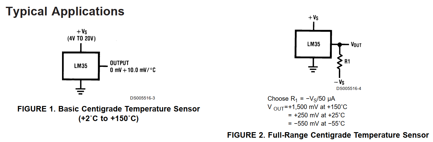
According to image below, when we connect the sensor like on the left, the temperature range we can get is between +2 to +150 celcius, but when we use right circuit we can measure temperature below 0 which is between -55 to 150 celcius. In this task, I use left image hence the measured temperature will always positive or above 0 celcius degree.
Accessing sensed value by LM35 is also simple. In this task, I use pin 4 that can be function as analog or digital input. I also attach VCC and ground to it. The snippet code of how to convert sensed value to celcius is as follow:
The demo is shown by video below. The downloadable program is below the video.
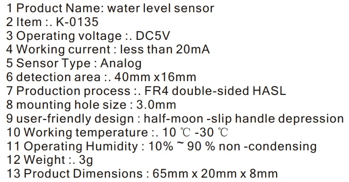
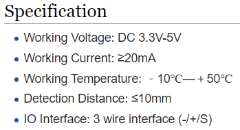
All files involved in this weekly task can be found on below link: Water Level SensorWater level sensor is a sensor that can measure level of water that touches its surface. This is an analog sensor that would produce value between 0 - 750. This is not level in meter. Based on the datasheet that you can find here, this sensor can work optimal with temperature between 10 - 30 celcius. This sensor can work on voltage around 5 V and current around 20 mA. This sensor is fabricated in FR4 PCB. It will detect the presence of water when it touches conductor strip over the PCB. We don't need further conversion over the read-out data as it can be directly used for further interest.
The code for this sensor is simple. In this task I use pin 4 in ATTiny3216 that can accept analog data, then data reading can be done using analog read command. I also use LCD to display the measurement result.
The demo is shown by video below. The downloadable program is below the video.
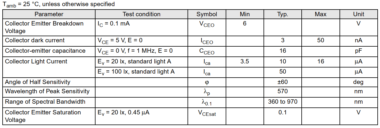
All files involved in this weekly task can be found on below link: Ambient Light SensorA sensor that can sense ambient brightness that utilizes TEMT600 sensor. This sensor can yield better precision according to the datasheet that you can find here. This sensor can work on with voltage between 3.3 - 5 V, hence it will work with the microcontroller. This sensor is incapable to measure ambient light when there are ultraviolet or infra red source around it. Similar to previous sensor, it can be read with simple analog read command. The value that we would get using that command will be in range from 0 - 1023, as it encoded in 10 bit ADC. To convert it to intensity and Illuminance, we should use some mathmatical formula that I found on this website. I do not have golden standard measurement tool to both entities, so I can guarantee the correctness of formula used on that website. This sensor similar with phototransistor that works like NPN transistor. Whenever source of light hits it (transistor base), it will flow current through collector pin. It can measure visible light with wavelength around 360 - 970 nm, with peak sensitivity happens on 570 nm according to the datasheet. Added to that, this sensor can measure ambient light effectively in 60 degree. Similar to aforementioned sensors, for this sensor I use pin 4 in ATTiny3216 to interfacing microcontroller and sensor.
To measure the intensity percentage, the read-out is multiplied with 0.0976 as shown by snippet of the code.
To measure the illuminance level, formula in the form of code below explains.
The demo is shown by video below. The downloadable program is below the video.
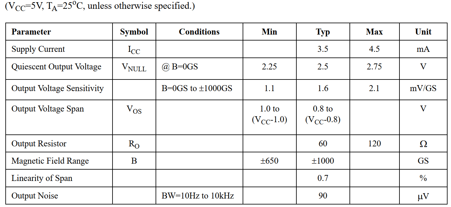
All files involved in this weekly task can be found on below link: Hall Magnetic SensorMagnetic sensor is a sensor that can sense the existance of magnetic field around it. This is type of passive sensor. So strength of magnetic field highly depends on the magnetic source close to the magnetic sensor. This magnetic sensor use AH49E sensor. According to the datasheet that you can find here, this sensor operates in 5 V Vcc. Typically, the magnetic field is around +- 1000 GS. When this sensor exposed with a magnet, the output voltage can span from 0.8 V to Vcc - 0.8 V, if Vcc = 5 V, then 0.8 V - 4.2 V. Supply current for the sensor is relatively small which is around 3.5 - 4.5 mA. Hence, you should put a resistor on the Vcc trace. This sensor gives integer value, where lower value indicates the presence of magnet field and vice versa. By using the integer value, you can set a threshold of how the microcontroller would responds. Based on my experiment, this sensor can sense north and south polar by placing the sensor to different face. There are 2 faces that this sensor has, use that to detect which polarity matches. When I test this sensor with magnetic tape that I am going to use for my robot, the sensor can detect the magnetic field only with very short distance around 0.5 cm. It means that I still need to look up for alternative sensors. In this task, I use pin 4 of ATTiny3216 that can be used as digital and analog input.
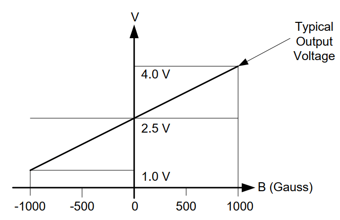
In the datasheet, they also provide the typical voltage response over sensed magnetic value as shown by figure below. By using this curve, I made a formula to estimate the magnetic field value by using Linear Transformation on Two Points. Lets say Y1 = 2.5, Y2 = 4, X1 = 0, and X2 = 1000. Then the formula to solve is
The formula is implemented in the code as follows:
The demo is shown by video below. The downloadable program is below the video.
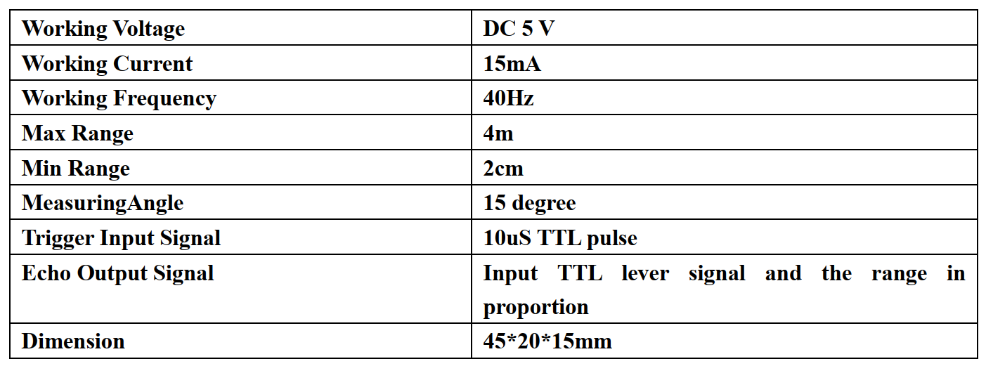
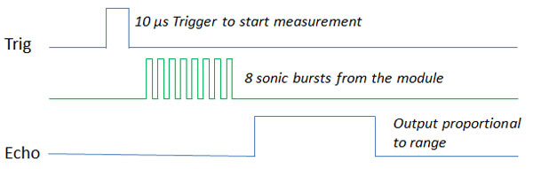
All files involved in this weekly task can be found on below link: Digital SensorThe DefinitionIn digital sensors, the signal measured is directly converted into digital signal output inside the digital sensor itself. The digital signal is transmitted via cable directly to the digital pin in microcontroller. ExamplesThere are a lot of examples of digital sensor like digital temperature sensor (DS1620) that I did not cover in this task, proximity sensors, reed switch as digital magnetic sensor and so on. Here I did experiments with some sensors that I potentially use in my final project. Ultrasonic SensorAccording to keyence, ultrasonic sensors measure distance by using ultrasonic waves. The sensor head emits an ultrasonic wave and receives the wave reflected back from the target. Ultrasonic Sensors measure the distance to the target by measuring the time between the emission and reception. The ultrasonic sensor I use here is HC-SR04. This sensor is popular among hobbiest because they are so cheap. According to datasheet here, this sensor transmit signal 8 pulse with frequency 40 kHz whenever Trigger pin is supplied for around 10 uS. It can send and receive signals from 2 cm - 4 m. We can give supply 5 V to this sensor. In my project, I am gonna use this sensor alongwith obstacle avoidance sensor-IR light based, to detect any obstacles that might block the movement of the robot. In this task, I used pin #3 for trigger pin and pin #4 for echo. The trigger pin is connected as output, while echo pin as input. When trigger pin set to HIGH, it will send ultrasonic signal to anything in front of it. When there is object that reflects the sounds, echo pin receives them. Then we use time needed by the ultrasonic signal goes back to sensor (echo pin) and divided by two. This result is used to calculate distance between object and sensor by multiplying it with sound wave velocity (340 m/s). The multiplication between sound speed and time is called as Newton law.
Snippet codes that explains how to read data from this sensor is as follows
The conversion from time to distance is
The demo is shown by video below. The downloadable program is below the video.
All files involved in this weekly task can be found on below link: Digital Magnetic SensorSimilar to analog magnetic sensor, this sensor detects the presence of magnetic field and outputs them in digital form, HIGH (1) or LOW (0). If there is magnetic field, then it yields LOW (0) and vice versa. This sensor is called Reed Switch and its shape is like a tube. Based on my experiment, the length of distance between magnetic source and the sensor depends highly on the magnetic strength of the source. If the source has stronger magnetic field, then the sensor can detect the source from longer distance. Of course this can be a trouble for my robot, as magnetic tape that I use is passive magnet. It means that they strength or magnetic force already defined. According to the datasheet that you can find here, that detection distance less than or equal to 10 mm. I tested and have the same value. It means that if I want to use this sensor as guide for my robot, I have to lay it down close enough to the magnetic tape.
As the sensor is digital, there is no need special mathmatical formulation for this. As we just need to use digital read for pin we connect to sensor, in this case I use pin 4, as this pin can be drived as analog and digital input pin.
The demo is shown by video below. The downloadable program is below the video.
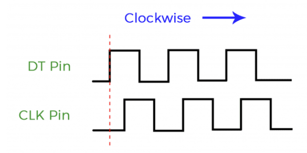
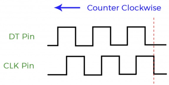
All files involved in this weekly task can be found on below link: Rotary EncoderRotary encoder is one of interesting sensor. People use this as real-time interactive control for display menu in a machine like 3D printer, CNC and so on. In this task, I use rotary encoder to do similar thing. I provide some menu in a form of list, then I put an arrow that can move UP and DOWN for navigation. There are 3 pins that play the most role in this sensor: DT, SW, and CLK. For rotary, DT and CLK pins would decide whether the rotary events clokwise or counter clockwise. See figures below to understand how they work. When we rotate the knob, the DT pin goes HIGH and at the same time CLK pin goes LOW. On the contrary, when knob is rotated counter clockwise, DT pin goes LOW and CLK goes HIGH at the same time. In order to responds, in the code, we should put routine to check this state then continue with some actions or events. According to my experiment, the sensor that I use is a bit unstable. When I rotate the knob for one click, it increments the value for two, for instance, 0 -> 2 -> 4 -> 6 so on. But when I keep rotating the knob, sometime the even number change to odd number which is strange. To cope with the problem, I add some control using conditional IF.
Code for this sensor is relatively easy by only using digital read and logic about how this sensor works. First, I use CLK pin for events reference:
Then I compare with state (logic) of DT pin to detect knob's movement (clockwise or counter)
If they are different, and CLK state is LOW then it is clockwise and vice versa. Do not forget to put a process
With this logic, I can navigate menu displayed on the LCD. I know that there are bugs in my code, anyone can use the code as basis to run. The demo is shown by video below. The downloadable program is below the video.
All files involved in this weekly task can be found on below link: Line Tracking SensorThis sensor is frequently used to navigate robots movement over black over white or white over black line. The line can be created using adhesive tape or paints. This sensor works as follow, it emits infrared (IR) light towards line. When it hits white line, then IR light is reflected and received by receptor. When it hits dark line, IR light will be absorbed. That is why we need dark and white line to give sharp logic changes to indicate the exact location of white line. Based on the datasheet that we can find here, this sensor can operate with 5 V Vcc. Pretty low current can drive this sensor to work which is less than 10 mA. I am not going to use this in my final project as I am planning to use magnetice tape instead of ordinary line, but this sensor is applicable in green house as higher working temperature for this sensor can reach up to 50 celcius degree.
This sensor will not be activated when it IR light hits dark surface. I have tested with other bright surface color like orange, the sensor is activated when IR light hits it. But, we can adjust the sensitivity using variable resistor attached in the circuit. To access the value read by the sensor, we simply use below command. I use pin #4 in ATTiny3216 connected to the signal pin on sensor.
The demo is shown by video below. The downloadable program is below the video.
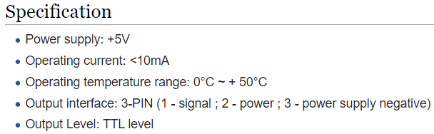
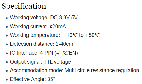
All files involved in this weekly task can be found on below link: Obstacle Avoidance SensorThis sensor is awesome as it produces logic changes whenever an object on its eyesight. I am gonna use this sensor to detect any obstacle in front of the robot to make robot safer as it stops before hitting the object. According to its datasheet that you can find here, the sensor can detect object with angle 35 degree. The distance of obstacles that the sensor can detect is between 2 - 40 cm. It can be drive with 3.3 - 5 V and can operate effectively in temperature between -10 to 50 celcius degree. This temperature is important information because the robot is planned to be used in a green house. Green house is a closed form building where the temperature can be higher than at the outside. The temperature usually ranging between 35 - 45 celcius degree in tropical country. Hence, it is safe for the sensor to operate optimally. The strenght of detection can be adjusted using variable resistor included in the pcb. But, we can develop our own sensor breakout with certain resistor value after doing some experiment about the strength.
As the sensor is digital, there is no need special mathmatical formulation for this. As we just need to use digital read for pin we connect to sensor, in this case I use pin 4, as this pin can be drived as analog and digital input pin. Basically, this sensor is built
base on infrared sensor. Infrared is one of sensor that can effectively detect object in Line of Sight (LOS).
The demo is shown by video below. The downloadable program is below the video. In this video, when object is placed perpendicular to origin (location) of sensor, it can be detected flawlessly. But when I shift the object to certain angle, close to 35 degree, the sensor becomes unstable. The detection is swinging which means that the infrared reflected by the object back to the sensor is not solid. Hence, the sensor cannot decide fully that there is an object in its line of sight (LOS). So, in my project, I am gonna use atleast 2 sensors on the front side of robot to get clear view so no part of the robot's body would get stucked by any obstacles might present in robot's way.
All files involved in this weekly task can be found on below link: Reed Magnetic SensorAs I have observed both magnetic sensors which are reed and hall sensors, I decided to use reed switch for my robot to navigating over the magnetic tape. The sensors module available in the market which was I used for testing, use LOW logic as the decision. It means, when magnetic field is detected by the reed sensor, it connect the circuit to ground and turn on the led. In my design, I do reverse. When magnetic field is detected, it will turn the led and send HIGH logic to microcontroller. It will be easy for me to make the code and understand the flow of the system later. Here is the schematic that I made. I use blue LED as indicator where the voltage between 3 - 5 V according to available information on the internet. I can't find spesific manufacturer that made the led I am using. I made different circuit at first, by using S8050 PNP Transistor (coded as J3Y), because I am to make sure the HIGH logic steady. It works very well but requires some more components in the circuit. So, I simplify the circuit as below and tested them with serial monitor and gave same result. Here is PCB drawing for single PCB. Here is PCB drawing for multiple PCB print. In order to do this, to speed up your development, you can copy-paste single module into empty area, but becarefull about your PCB's size. Here, my PCB size is 10 cm x 15 cm. Here is the video demo of the reed switch. I made the design according to my needs for the robot. I |
Table of Contents
|