Week 7 - Computer-Controlled Machining
group page // repo source files // objectives
Contents
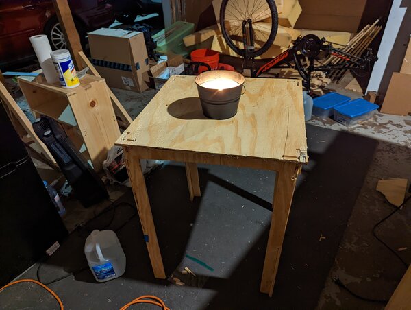
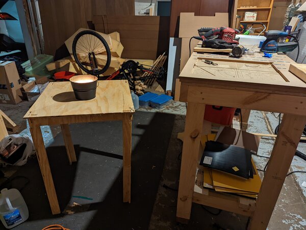
hero shot >
objectives >
- Linked to the group assignment page
- Complete your lab’s safety training
- Test runout, alignment, speeds, feeds, and toolpaths for your machine
- Document your work to the group work page and reflect on your individual page what you learned
-
Documented how you designed your object (something big)
- Documented how you made your CAM-toolpath
- Documented how you made something BIG (setting up the machine, using fixings, testing joints, adjusting feeds and speeds, depth of cut etc.)
- Described problems and how you fixed them
- Included your design files and ‘hero shot’ photos of final object
concept >
I did quite a bit of brainstorming for this one. Initially, I had an idea for a suit of armor that would double as armor, or a chair. I dubbed it arm(or) chair.
However, I quickly realized that it might be too daunting for a hello world, applying CNC machining principles.
Previously, before fabacademy, I spent time making 2x4 furniture to make my spaces more usable. These included workbenches and “modular” coffee tables.
I’m overdue for some more furniture, so I started off with a basic lack-like table.
safety >
shopbot is only machine that could seriously injure or kill someone in MSI fablab. MSI follows industrial “lockout/tagout” procedure that complies with OSHA.
- one person locks out machine
- machine is considered “tagged out”
- technically everyone has their own tag with own name
- this tag is used to lock the machine
- usually has a physical barrier preventing movement from anyone else in work area
- person operating the machine has an e-stop button on person at any time around machine
design >
basic >
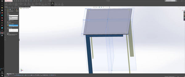
The idea was to make a table that assembled w/o fasteners, and ideally had flexible surfaces. I started with the fasteners criteria.
2ft x 2ft top, which matches a lot of my other furniture
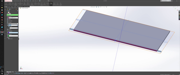
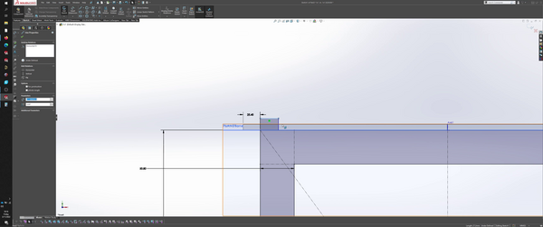
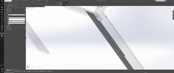
side profile for el-leg.
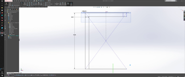
joint between top and el-leg.
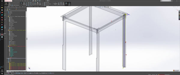
circular pattern to repeat feature for all 4 corners.
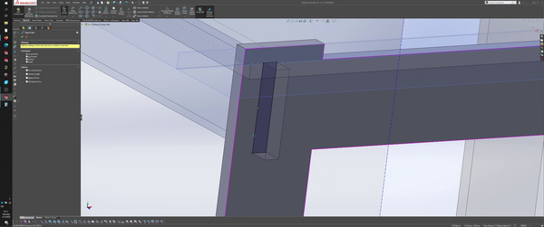
another joint to constrain el-legs to each other. Assembly might behave in a zipper-like fashion, may need to add a chamfer to the edge here for easier insertion.
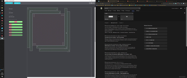
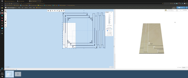
nesting >

I had been meaning to use deepnest for the laser assignment, but didn’t find the time to. It’s only fitting that I used parts from the laser cutting assignment to test out deepnest, in preperation for this assignment.
one of my motivations for my 1x1 table hello-world was to create a design that was easily nestable and optimized space usage. I still need to design the table to optimize for standard stock sizes, but it seems to do a pretty good job compared to a more traditional pattern, such as the One to Several Table from AtFab. I used that table for reference during design.
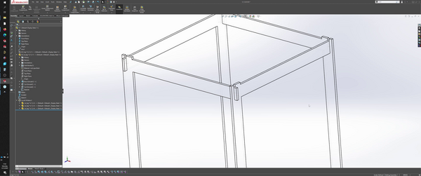
more design >
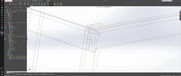
added an additional leg piece to further constrain table.
model is not very parametric and I didn’t account for an extra part initially.
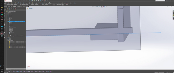
corrected by measuring offset and adjusting the sketch plane.
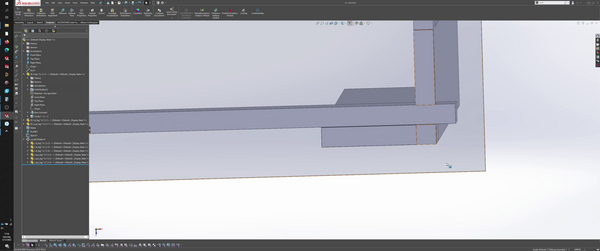
rebuild errors, on making cuts to fit joints together, removed some edges being used for reference in sketch.
using design checker to identify problems.
as far as I am aware, dxf export must be manually done to each individual part. Wonder if there is a more automated workflow in SolidWorks. If not, maybe export as step file and pass it through freecad? mods?
dogbones >
I tried to use the mods plugin for dogbones but fell short… mods is sorely in need of more easy to access documentation. I did however learn a bit about the history of mods.
scalemodel >
a common practice that I’ve picked up to get around SolidWorks assembly feature limitations is to save an assembly as a part. I scaled the entire assembly down for prototyping purposes, which Dan, Kyle-Pierre, or Blair mentioned.
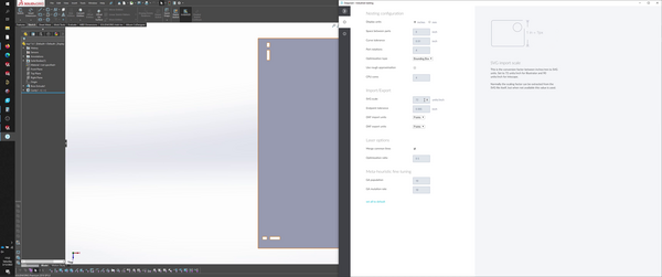
CAM >
using Easel for my CAM software, per Dan’s recommendation.
- feedrate
- 3048 mm/min
- plunge rate
- 914.4mm/min
- depth per pass
- 3.2mm
- spindle speed (RPM)
- 24000
- using a 1/8” bit
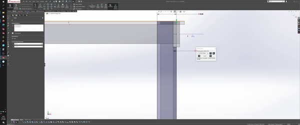
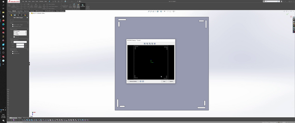
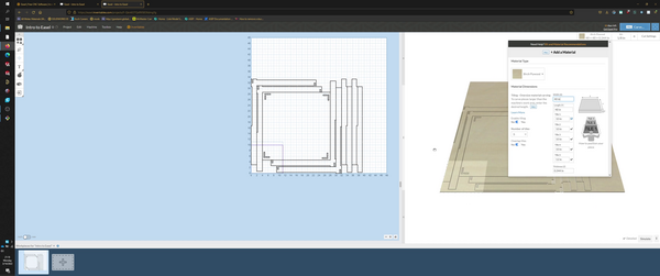
imported nested file, doesn’t fit stock.
resized stock.
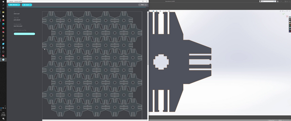
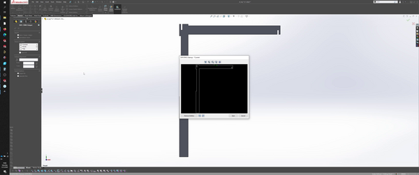
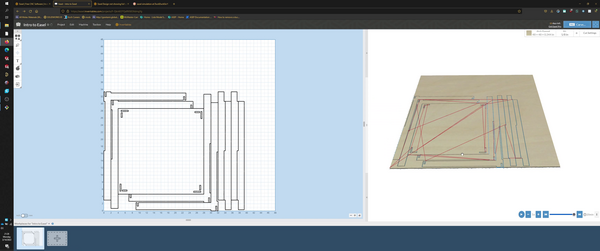
unfortunately, simulation space appears to be constrained to tiny box. turns out, constrained simulation space is due to a tiling feature in the settings. on turning it off, simulation space is no longer constrained.
the simulated path is shown to the right.
unfortunately, I don’t have access to a large format CNC (that isn’t the shaper origin) at the moment, so we’ve opted to kick the can down the road until I can find a large format CNC to complete this assignment.
machining >
Kyle-Pierre graciously offered his large CNC (Forest Scientific) to help complete the machining portion of this assignment.
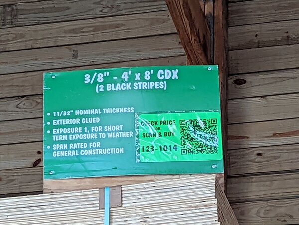
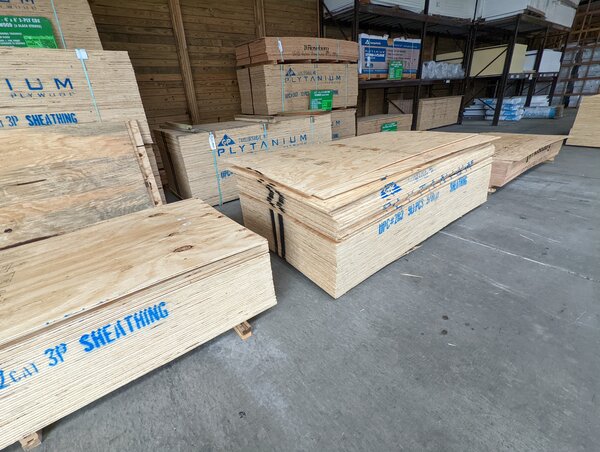
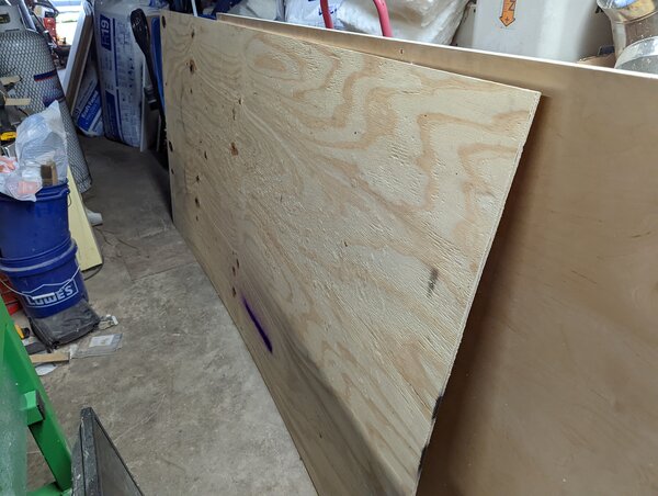
picking plywood >
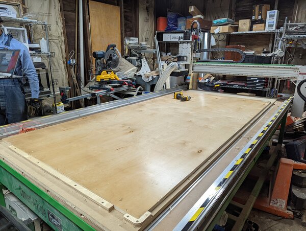
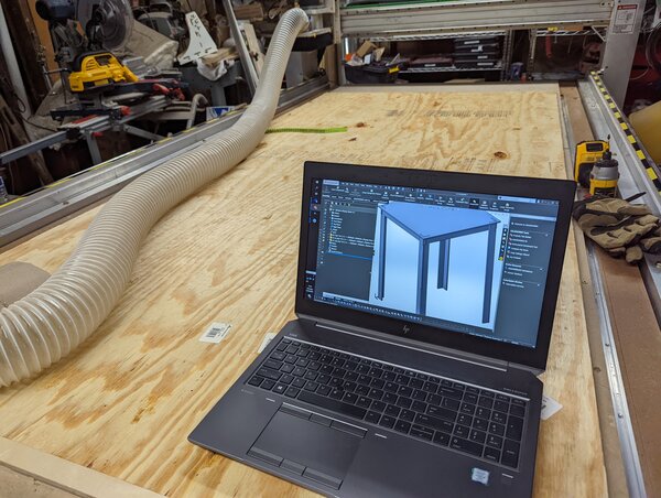
the machine >
This thing is massive. I personally own a shaper origin, but I usually work on 2’ x 4’ sized stock. Really puts space into perspective, and reinforces why safety protocols are important while operating these machines.
air compressor, cleanup >
To start, we prepare the bed of the machine by cleaning it so we can load my stock for cutting.
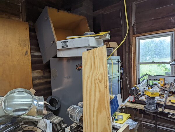
The compressor itself is tucked away in a corner.
loading my 11/32” stock and checking index >
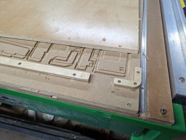
checking the index is important, to make sure the stock is square with the machine. If your nested design fits to the outline of the stock, then you’ll definitely want to make sure its square.
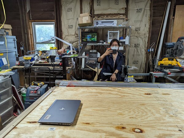
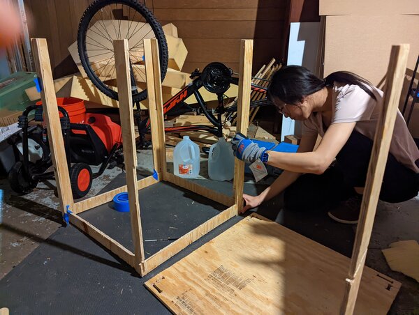
my gf Fong, helping me document :)
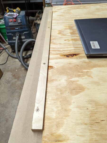
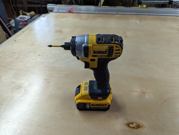
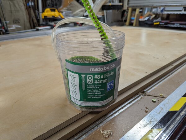
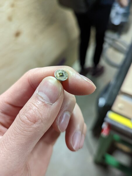
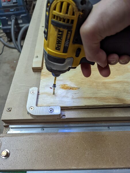
impact driver, fixturing >
the impact driver is a nice tool for installing fixturing fasteners, since the screw + impact driver make for a self-tapping combo. This means I don’t need to drill a pilot hole prior to screwing.
Kyle-Pierre has this DeWalt 20V impact driver.
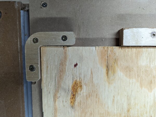
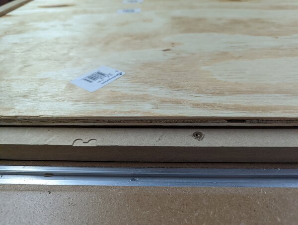
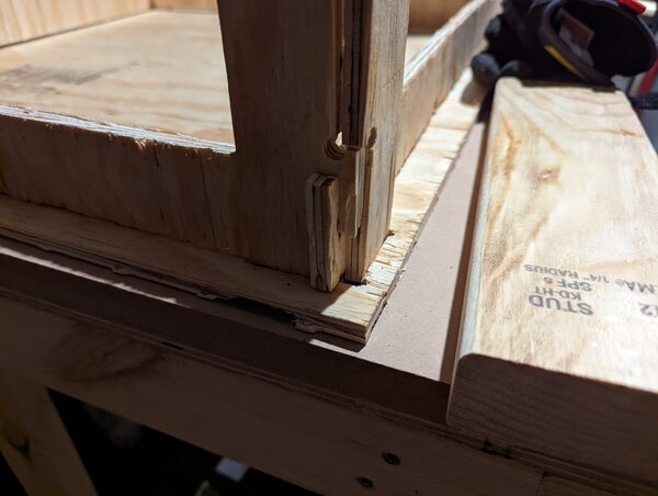
searching for “bubbles”, to smooth out the sheet. Similar to squeegee’ing a new screen protector onto a phone, want to force the air out in a single direction to avoid creating trapped air bubbles.
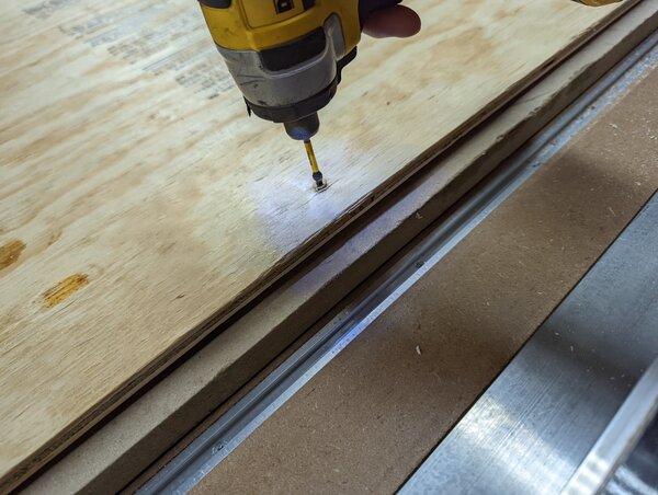
the gap depicted below indicates that the bubble in this area wasn’t smoothed out, so the screw fixturing this area needs to be removed and replaced after smoothing out the sheet.
CAD -> CAM >
I initially ran all of my CAM through Inventables Easel, but in an effort to streamline the process, I ran the CAD through the Fusion360 CAM process, which Kyle-Pierre is familiar with wrt his Forest Scientific machine.
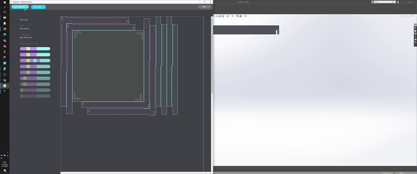
First, we bring the model from SolidWorks into Fusion360.
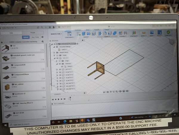
Next, we have Fusion360 arrange the components onto the stock.
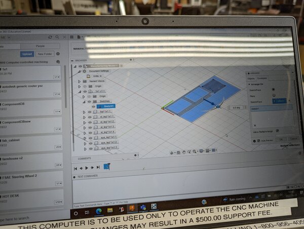
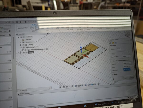
and then create a new setup for our arrangement, using a 3-axis CNC router configuration.
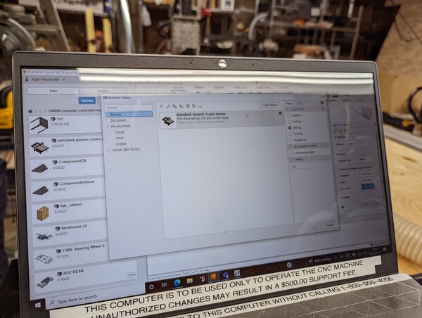
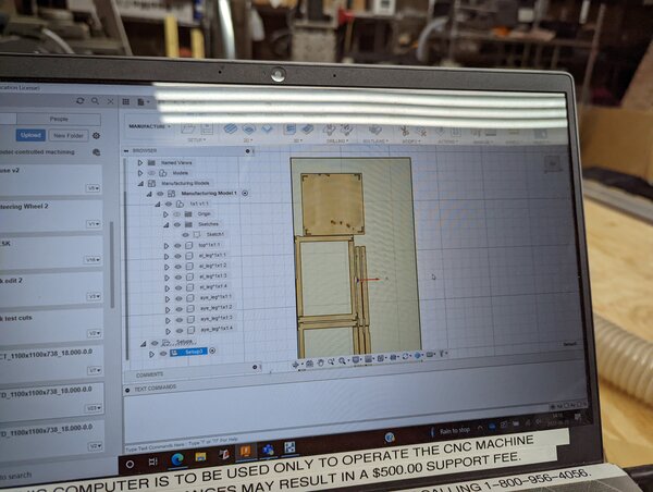
We jump through a lot (a lot) of dialog boxes, configuring many settings to make sure the arrangement will work for the Forest Scientific.
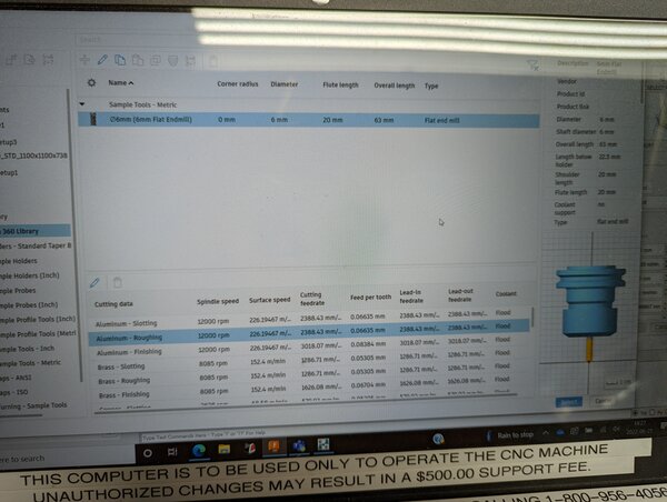
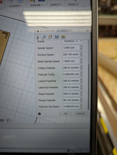
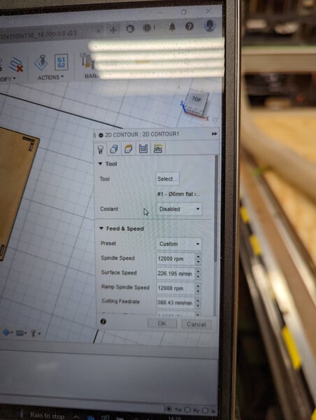
Finally, we reach selecting the endmill and configuring feeds and speeds away from some of the default profiles (we modified parts of an Aluminum rough-pass profile to be more suitable for plywood).
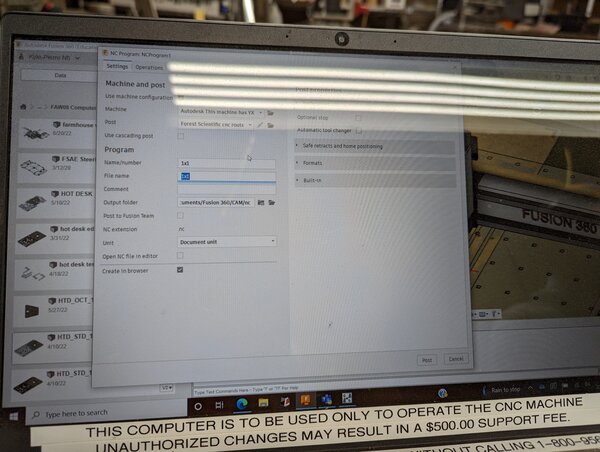
The Machine and Post dialog is the final step between the Fusino360 CAM software and the program that drives the Forest Scientific.
Similar to a 3d printer, the CAM software (3d printing slicer) generates machine code in the form of an NC program (3d printing gcode) that gets passed to the machine.
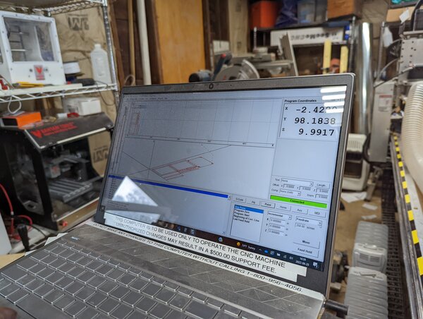
Shown in Fusion360, a simulation of the toolpath.
And finally, the NC program loaded, ready to run on the Forest Scientific.
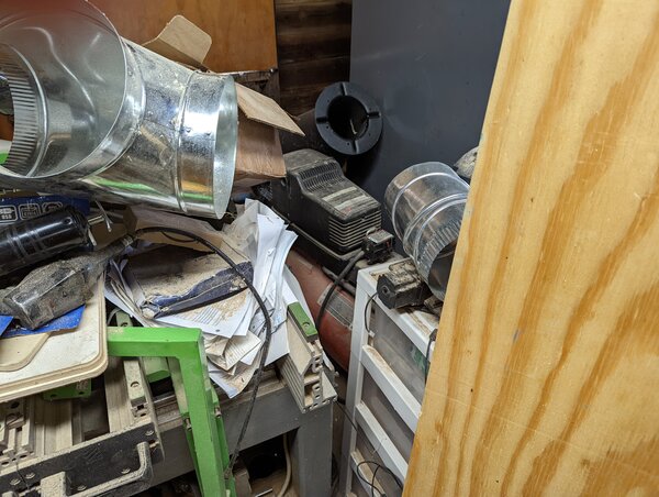
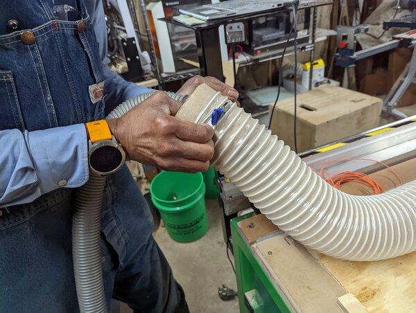
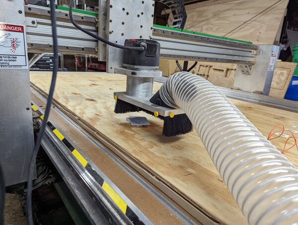
vacuum >
Kyle-Pierre has a large air compressor hidden in another corner of the room. He hides many things in these corners.
Neat trick: He uses a piece of cardboard as an adapter between the two sizes of tubes. In my garage lab, I designed and printed a plastic adapter, but this piece of cardboard seems to do just as well and probably takes less effort.
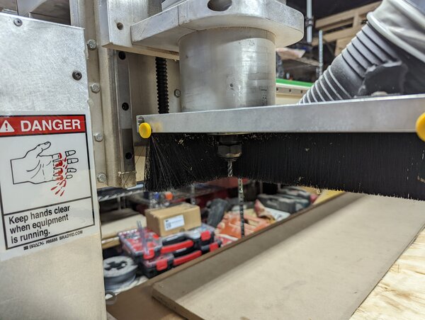
changing endmill >
To change the endmill, I untightened the collet with the wrench, swapped the endmill, and then placed a z-probe under the endmill to re-zero the machine. You can see the z value change in the video below as the machine re-zeros.
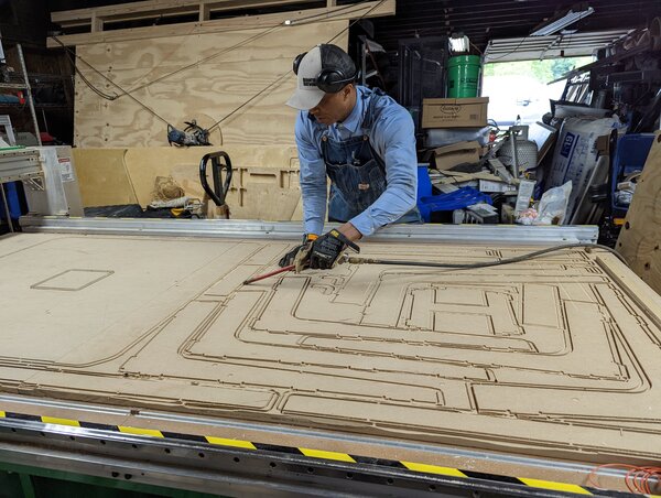
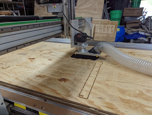
machining time >
As you can see, this part of the stock wasn’t fixtured properly and is moving up and down with the motion of the end mill. Path planning and proper fixturing go hand in hand, and require some forward thinking about which parts will become freely moving members.
machining results >
despite the dust shoe, post-vacuuming is still a necessity. The shop smelled of saw dust, which is good because burning means we pushed the endmill too hard. Since we were constrained on time, we did run the CNC router relatively fast.
Previously, I had experienced creating embers with a 1/4” endmill on the shaper origin. My friend, who I was instructing, was pushing the endmill a little too slowly for her design. The endmill may have also been dull, as it was one of the older ones I had at my disposal.
fires are particularly dangerous with a vacuum, as embers can potentially ignite the dry sawdust collected in the bag.
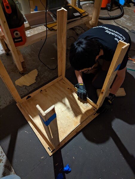
fit >
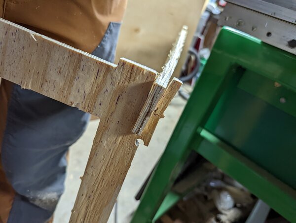
filing >
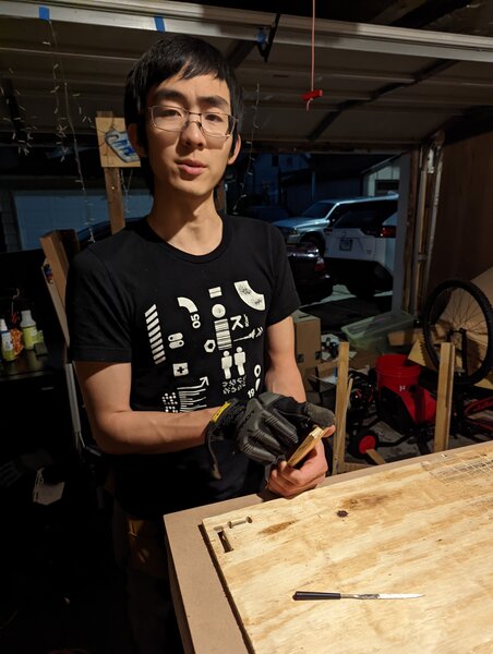
hammering >
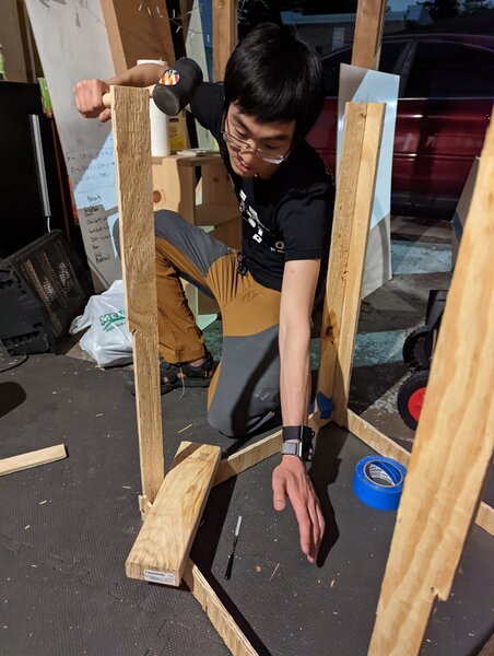
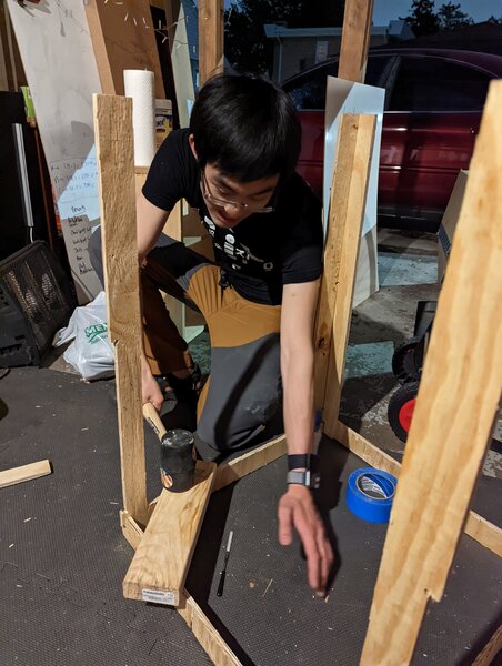
final assembly >
hero shot >