Week 3 - Computer-Controlled Cutting
group page // repo source files // objectives
Contents
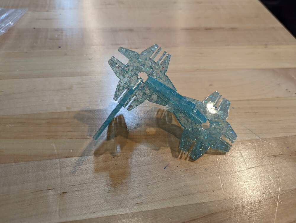
hero shots >
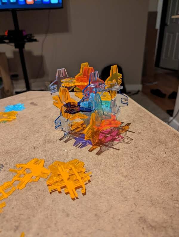
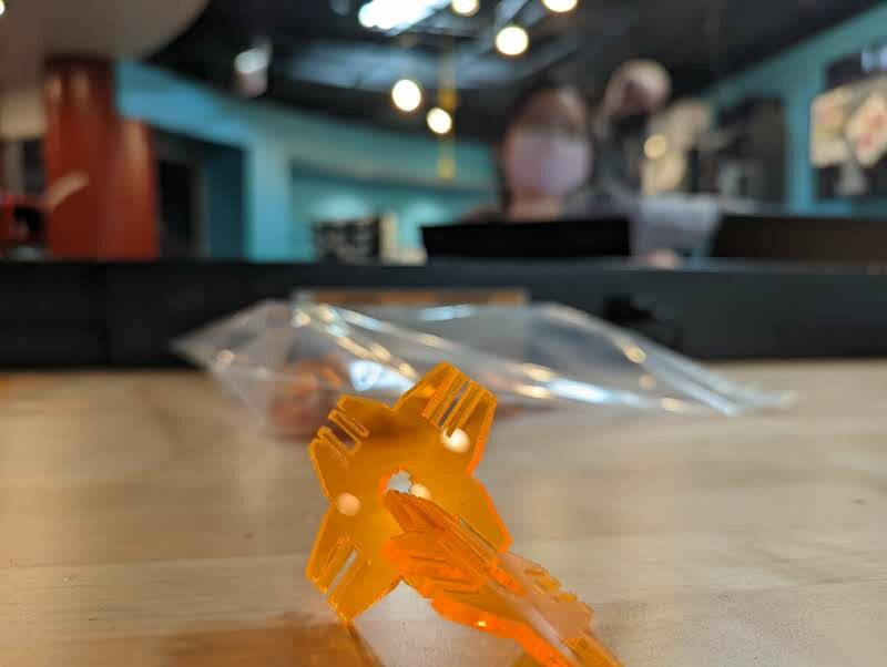
laser-cut press-fit kit
in the background: my friend who originally suggested the idea
weeding the flash
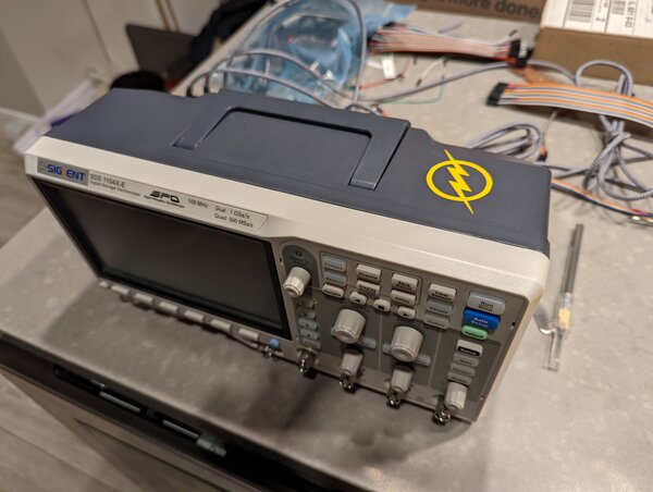
oscilloscope, powered by the speed force
objectives >
- Linked to the group assignment page
- characterize your lasercutter’s focus, power, speed, rate, kerf, and joint clearance
- Document your work to the group work page and reflect on your individual page what you learned
- Documented how you made your press-fit kit
- Explained how you parametrically designed your files
- Included your original design files
- Included your hero shots
- Documented how you made your vinyl cutting
- Explained how you parametrically designed your files
- Included your original design files
- Included your hero shots
msi intro >

press-fit kit >
I spent time replicating Neil’s joints example to better understand how one might reconfigure a design to use different joint types, and to understand their geometry better.

Neil's joints example, linked from his lecture
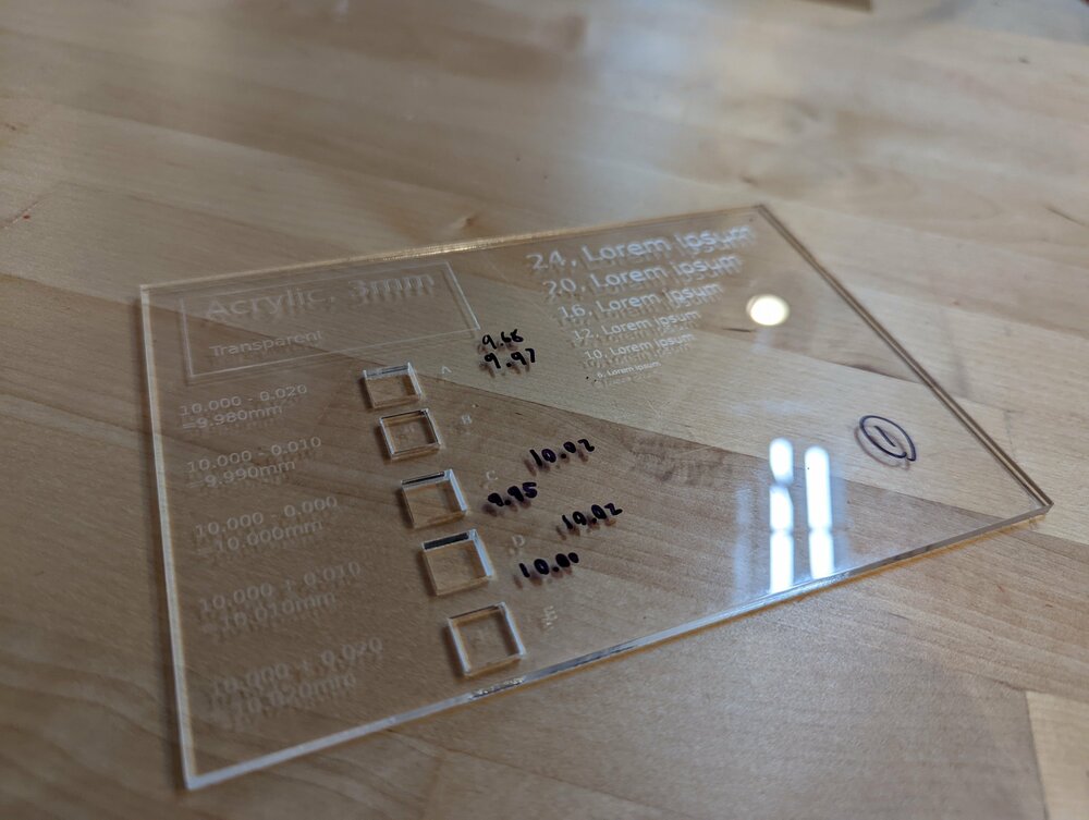
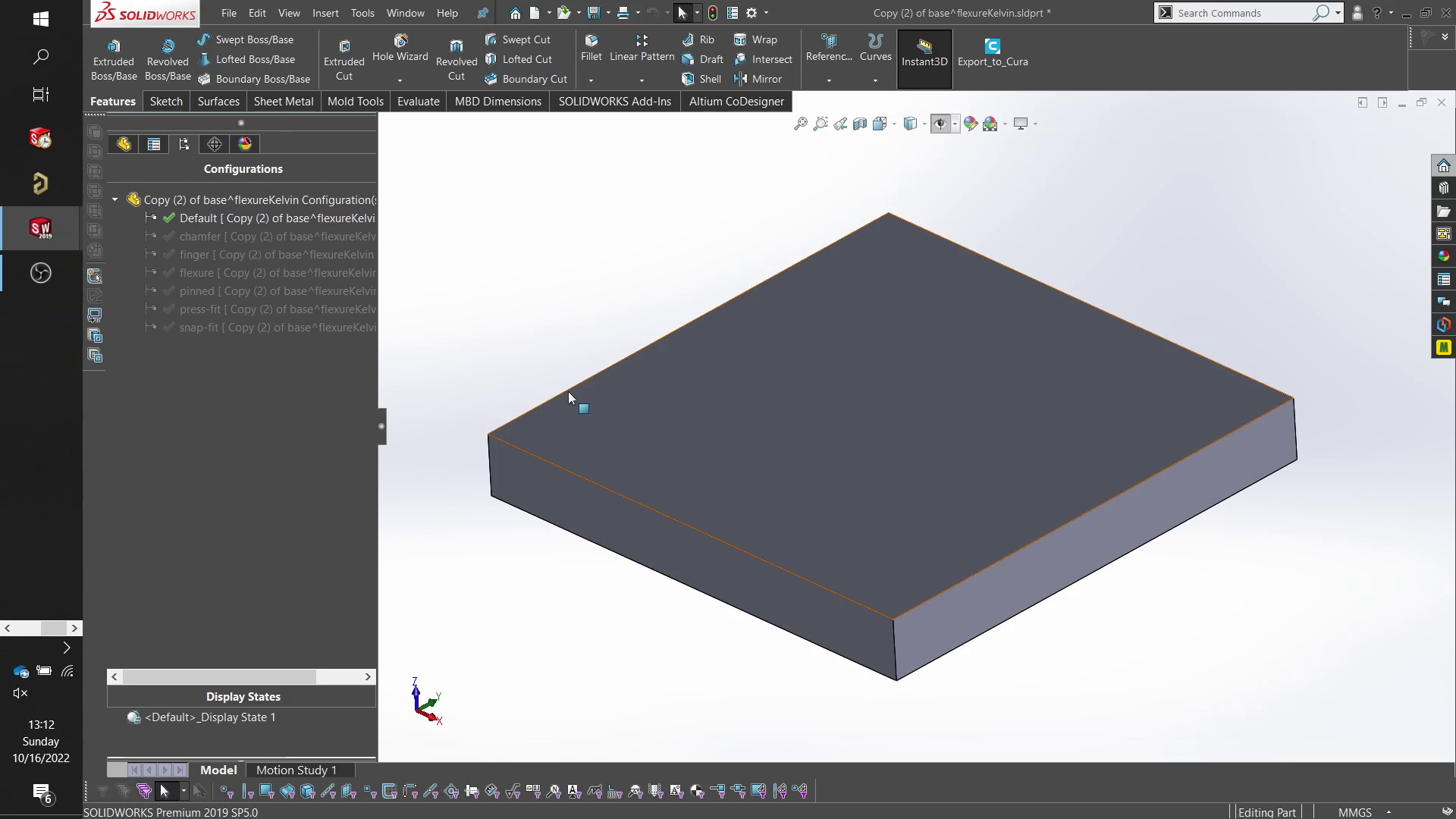
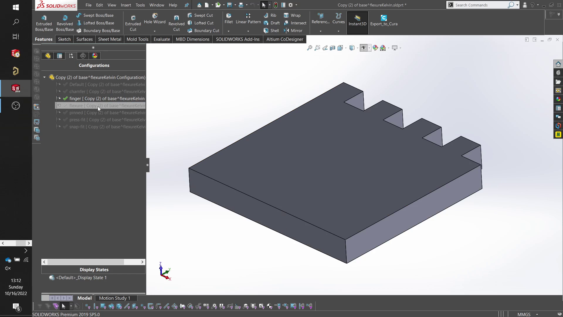
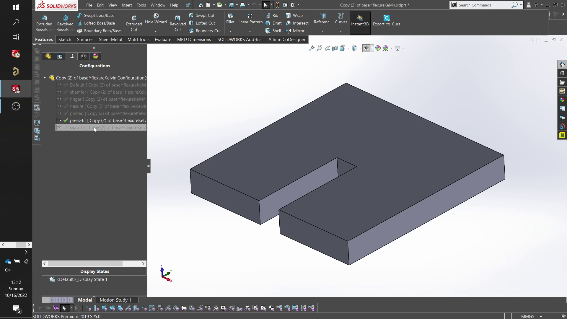
CAD - parametric joint model design study >
View configurations is a powerful tool in SolidWorks that allows you to vary which features to suppress and express. As far as I’m aware, capable MCAD programs typically have a synonymous feature.
Since all of Neil’s joints are variations of one another, it makes sense to have a base set of features make up the body of the joint, and have variations of features make modifications on the joint.
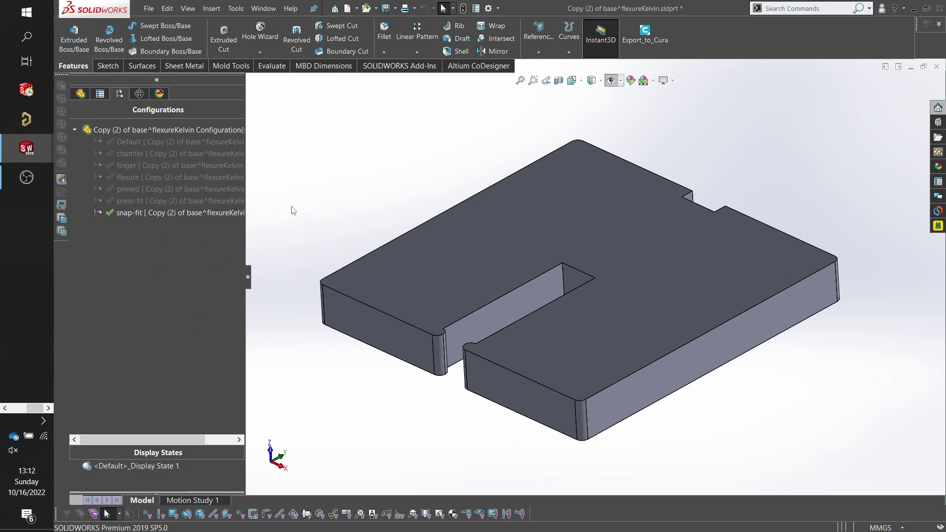
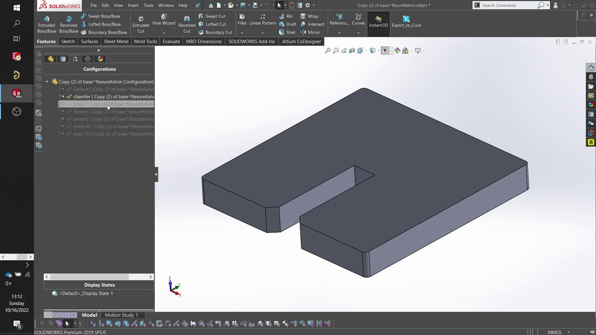
The different configurations:

CAD to CAM >
from CAD, you can export a .DXF, which is a vector file. This can be further manipulated in InkScape, to be exported as an .svg or .pdf.
In the MSI fablab, the computers controlling the laser are conceptually separated from the design computers. This way, no one can hog the laser machine because they’re stuck fiddling with their design.
I bring my .pdf to the laser computer on a flash drive.
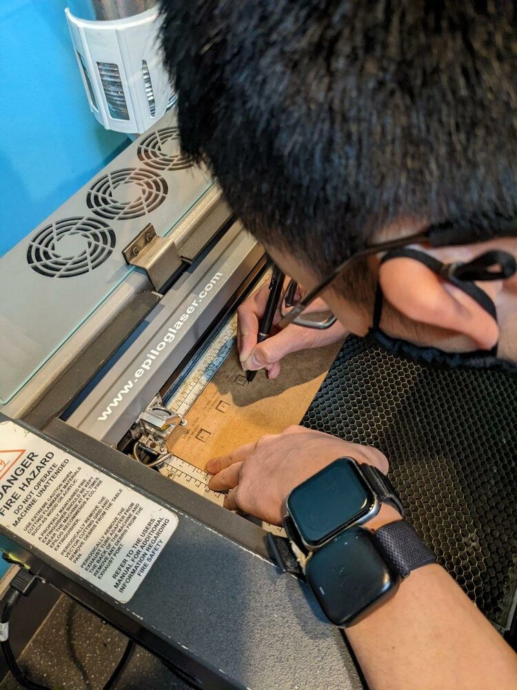
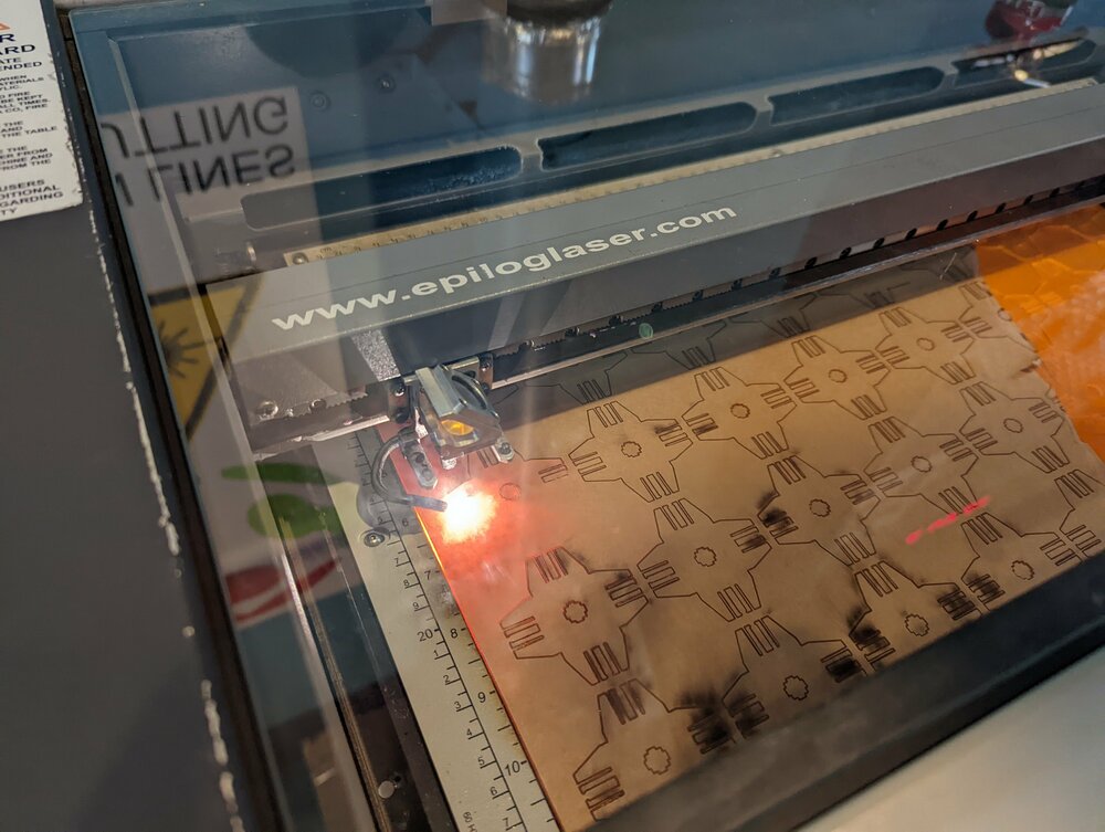
CAM >
Dan helped walk me through how to operate the Epilog laser.
…
After I opened the .pdf of my design, the first step is to print it like any other file you send off to a 2d printer.
ctrl-p
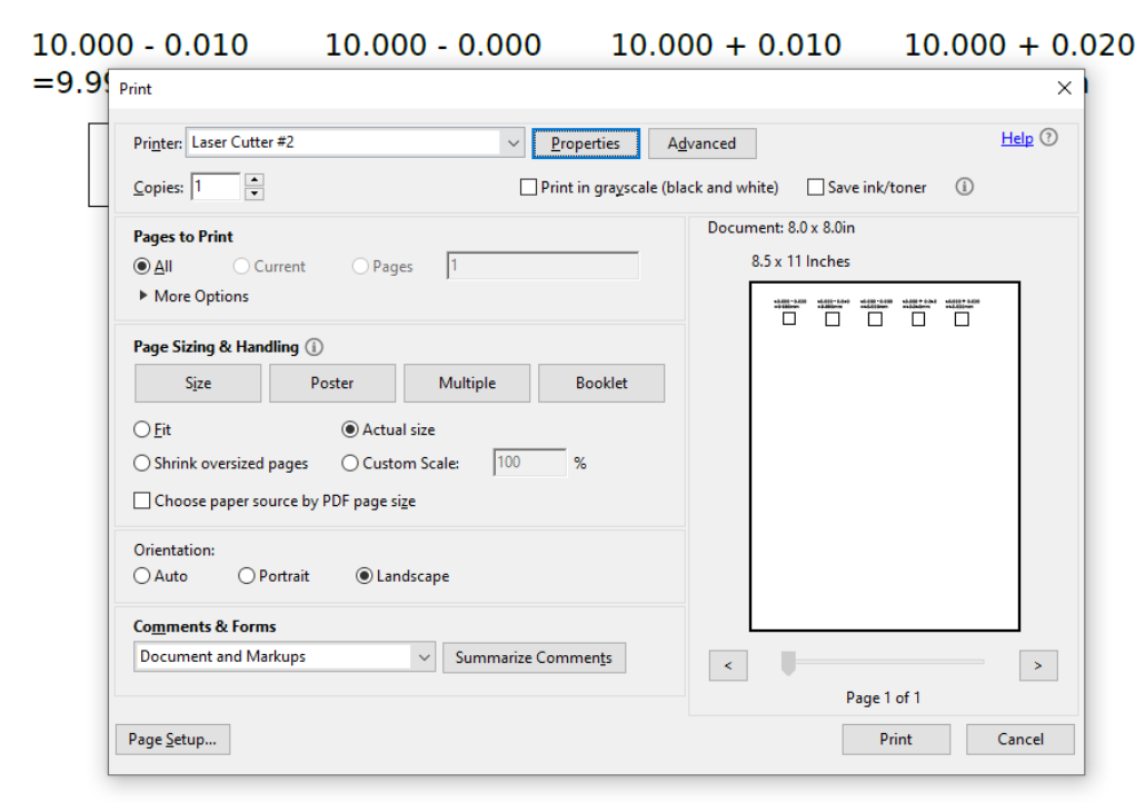
We’re met with the print dialog.
Laser settings can be selected from preconfigured profiles or set manually; profiles are accessed from the “Advanced” tab and manual settings can be configured from the “General” tab.
More details can be found from the group page.
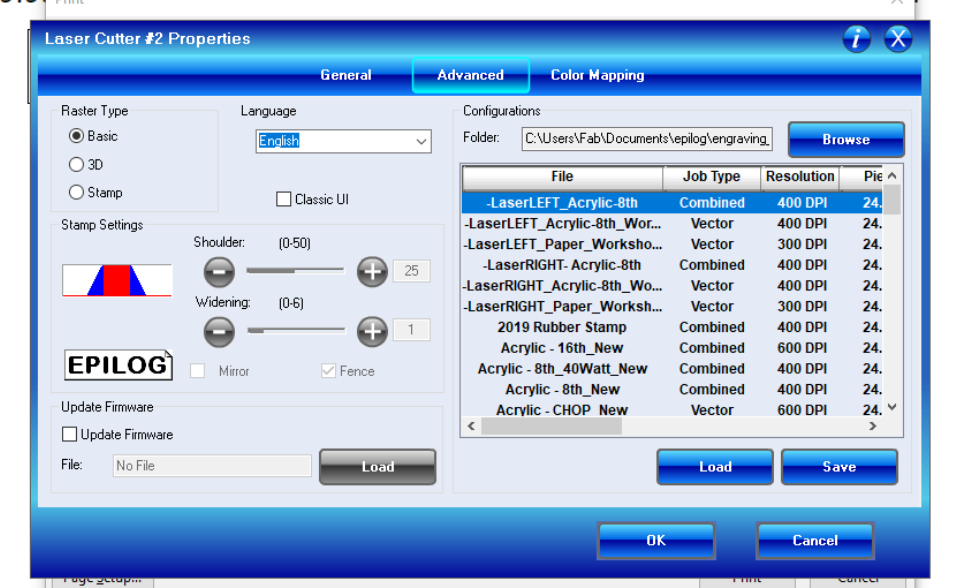
Advanced
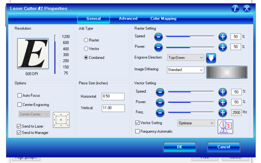
General
With profiles selected and settings configured, we can send the job to the printer.
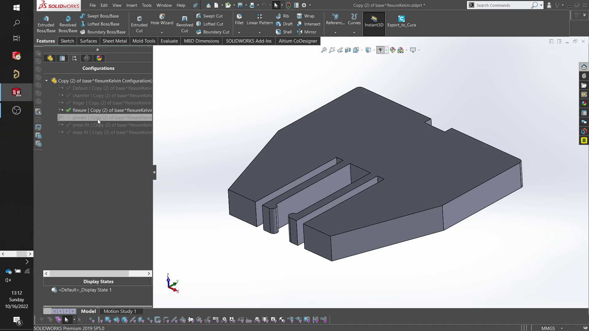
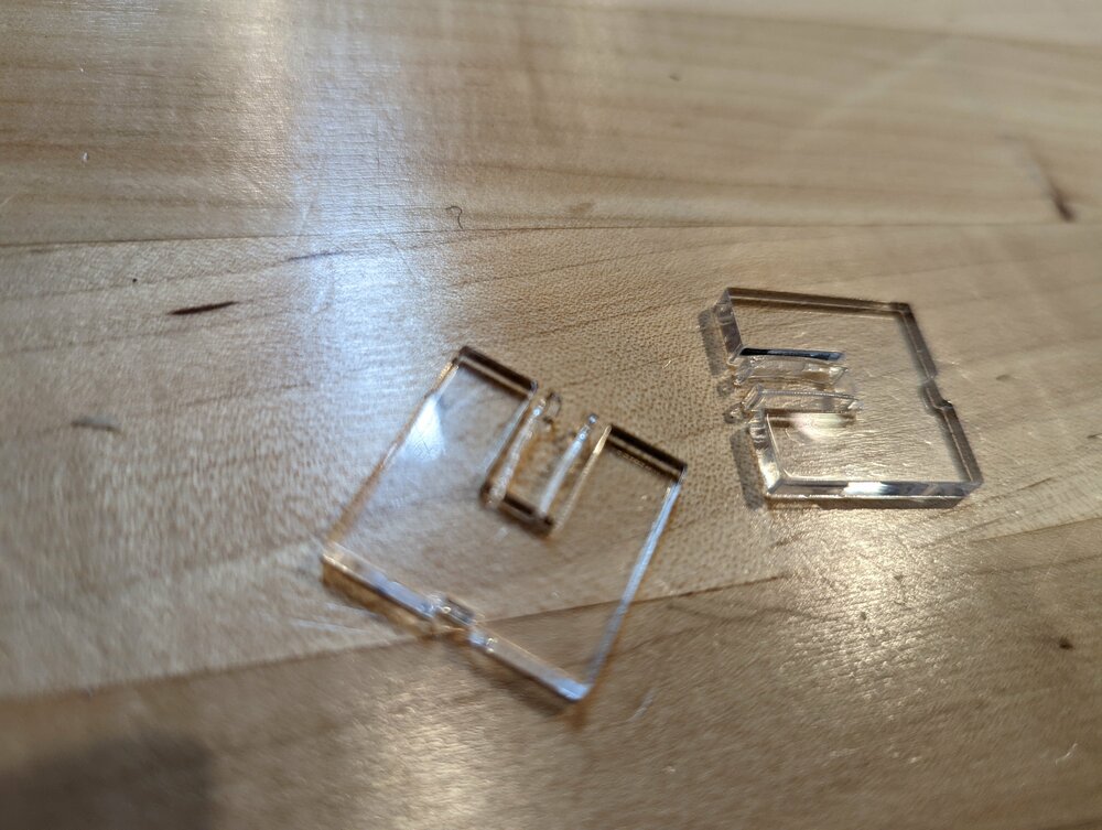
snap-fit and flexure parts >
Initially started with snap-fit and flexure.
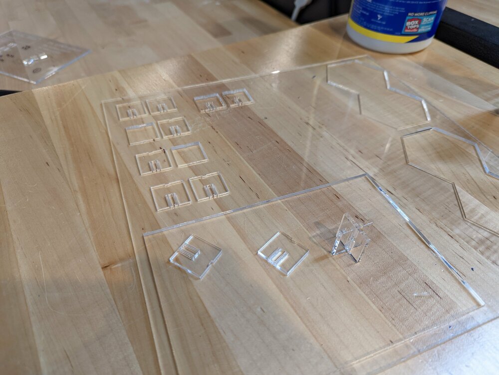
Found the snap-fit to be too stiff and wanted to focus on flexure, so made some more using clear acrylic.
CAD - parametric construction kit >
After playing around with the joints a bit, I took my demo joint part and brought it into an assembly.
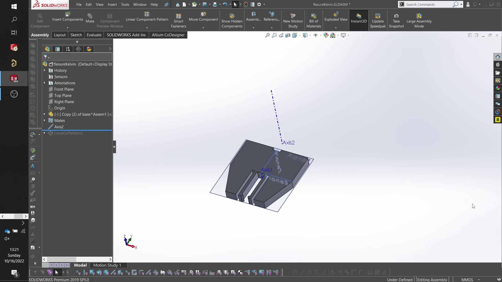
From there, I created an axis and circular patterned 4 of them.
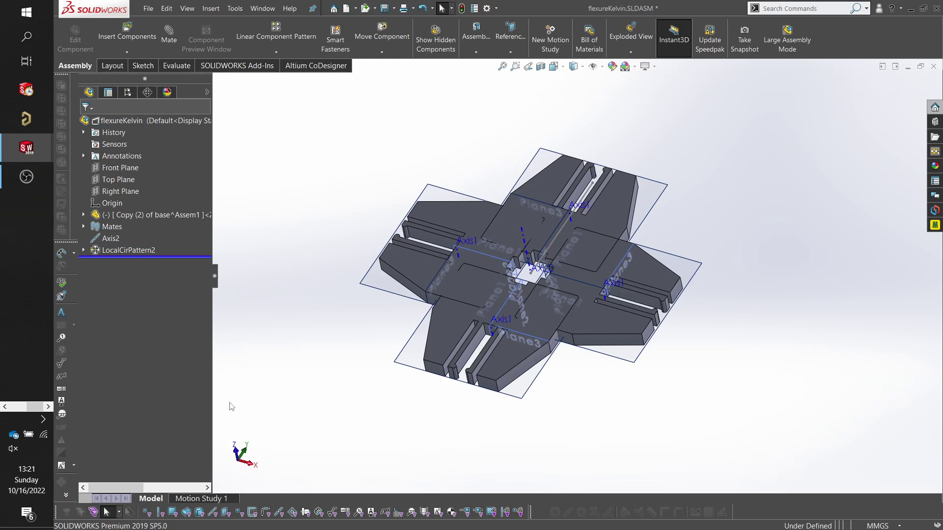
For some additional commands required to go from design to laser, I had to save my assembly as a part. As a part, I was able to use the combine command to create a single body. I was also able to save the part as a dxf, something that I can’t do with an assembly (not sure why).
I brought the dxf into inkscape and used their gridding feature to nest the parts onto a 12x24” sheet. In the future, I want to use something like deepnest to more efficiently use the material.
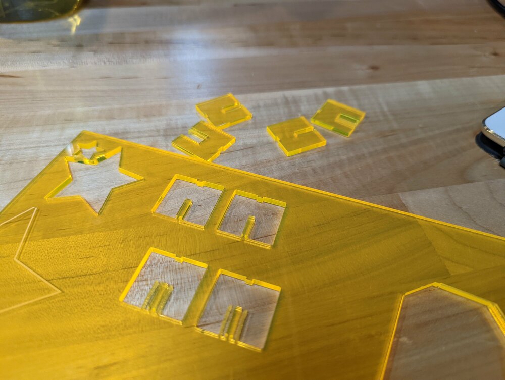
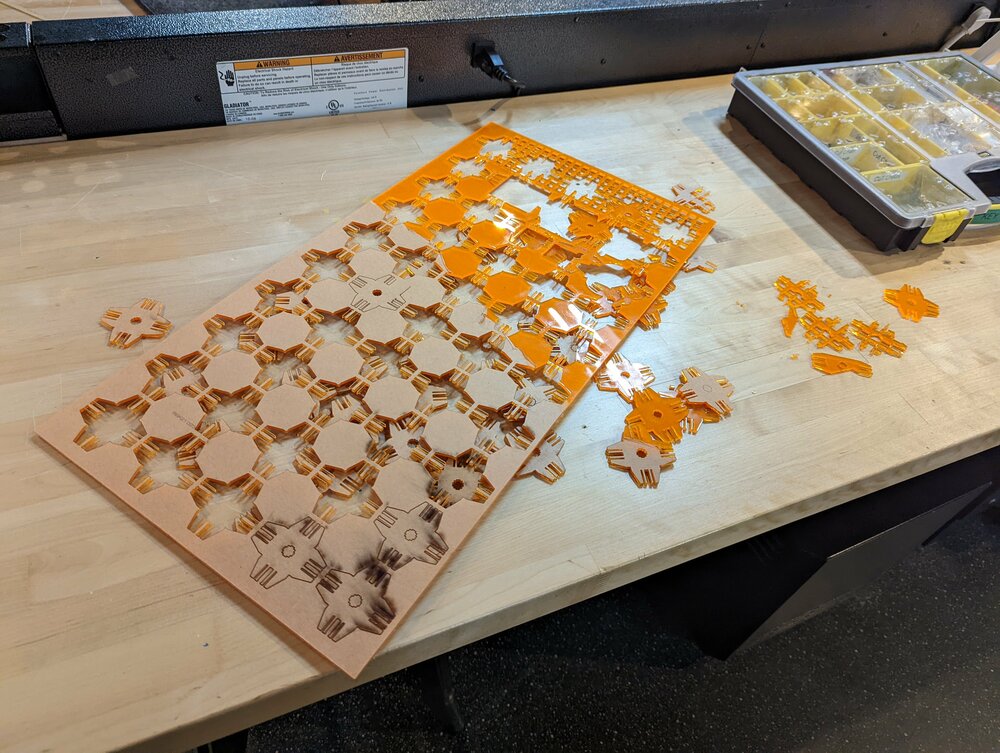
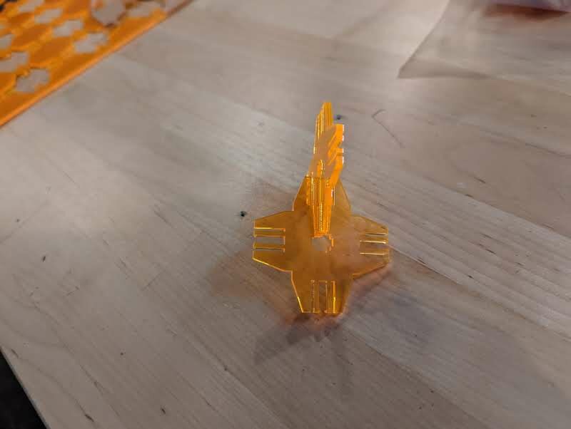
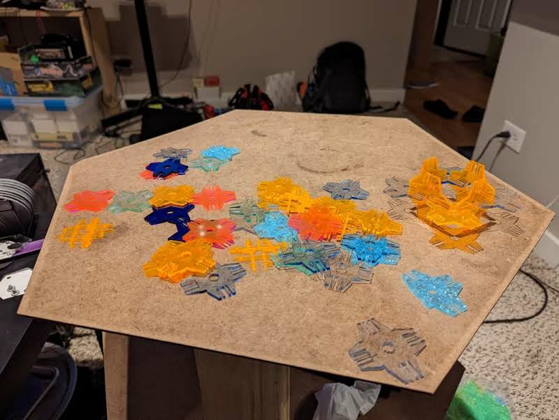
Fabbing sheets of kelvin-like geometries.
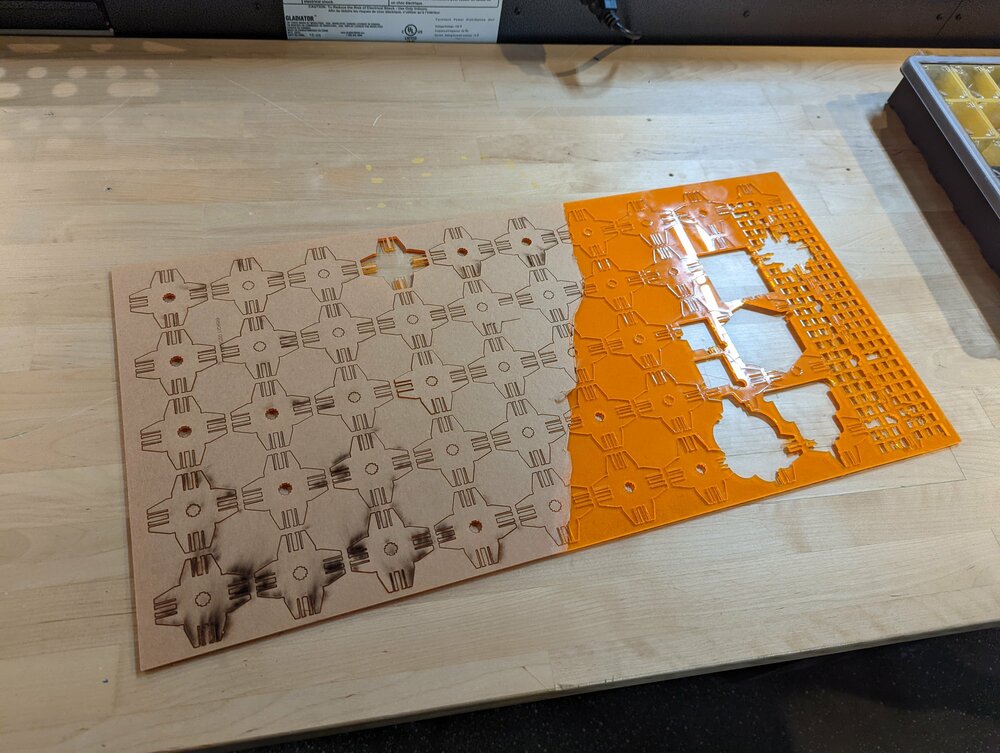
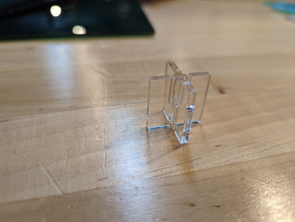
Join test.
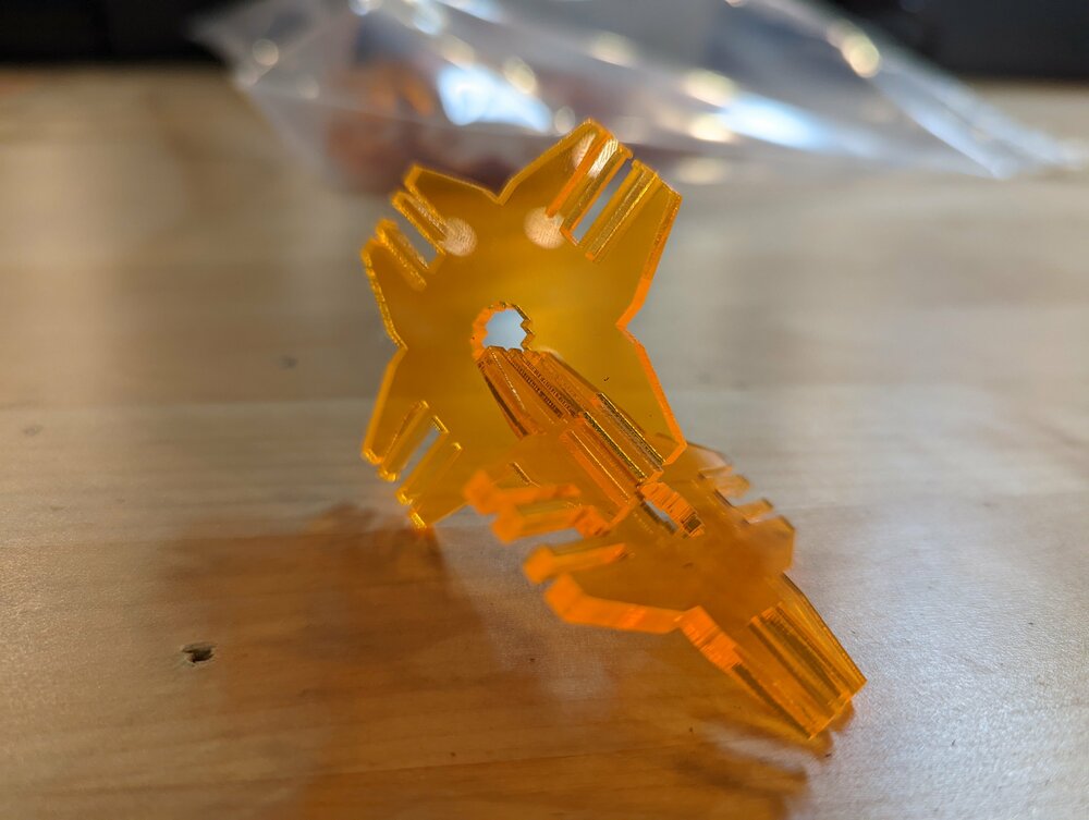
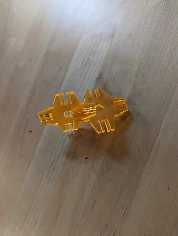
Trying a different color.
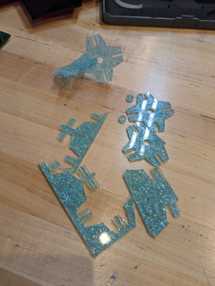
If you look closely, you can see a flexure broke off (I should’ve added more blends).
I learned quite a few things about lasers through this exercise:
- blends are really important, especially with flexures and brittle materials (like Acrylic)
- I forgot to add blends to the base of the flexure, and broke a lot of flexures…
- small features are prone to warping from the laser, because the laser lingers in an area for longer than normal
- similar to how 3d printing small features w/o cooling turned on can result in ice-cream swirls
Final result >
vinyl cutting >
axon cube stencil >
I spent some time brainstorming about what I could cut with the vinyl cutter. I tried to limit how much time I spent brainstorming, to avoid spiraling too far like I did with the lasercutting portion of the assignment.
A few weeks ago, I had a conversation with a friend who liked to sketch. He had a tendency to draw axonometric cubes (new word of the day!). I thought it was a stylistic choice, but after talking to some more of my artist friends, I learned that framing is very important for drawing. Cubes can be used to literally guide the artist to draw within the box. That makes sense; I prefer grid paper for a reason (even if I don’t follow the lines very much).
My friend was ideating on a lasercut stencil, but I realized that this was a better fit for the vinyl-cutter, due to the thickness/type of material.
Solidworks >
I initially thought about making the design directly in inkscape, but concluded that modeling in Solidworks would give me freedom over the perspective. I took some inspiration from Tarek, whose page I happened upon while digging through the 2021 students.
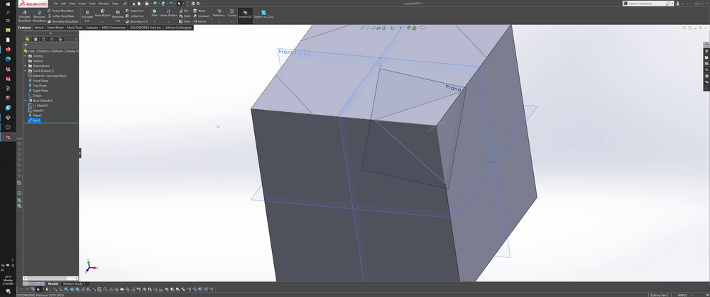
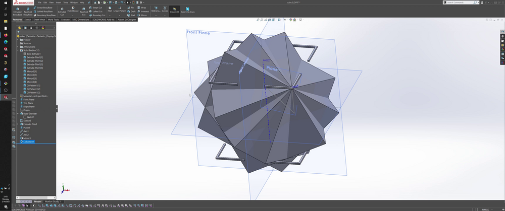
I started by modeling a cube
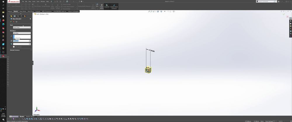
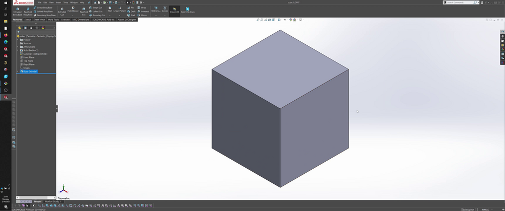
At this point, I thought I was done… but I quickly realized I wouldn’t end up with a working stencil.
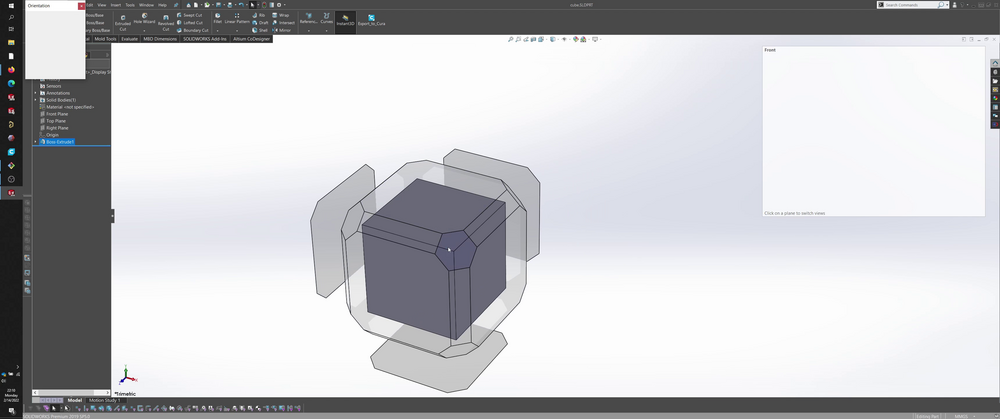
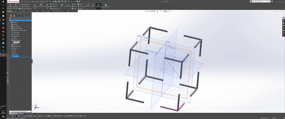
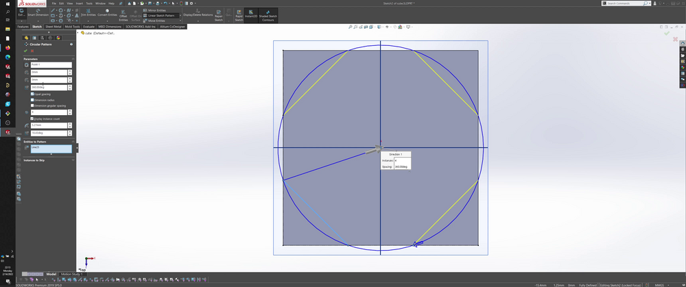
Using the cube as a reference, I sketched lines on one face to outline the corners; I only want to capture the corners in my stencil, not the entire cube outline. I made a few attempts to pattern/mirror the sketch with limited success.

I ended up applying a thin-line extrusion using the sketch, which gave me features/bodies that I could then use traditional pattern/mirrors.
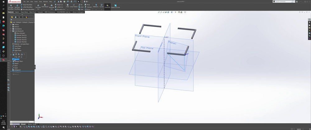
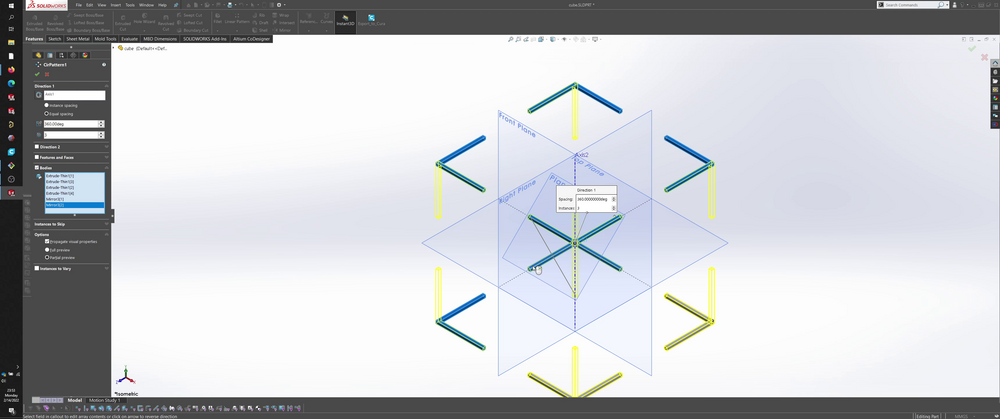
Circular pattern: I created a plane that intersected the cube diagonally, which I then used to create an axis that went through a diagonal of the cube.
Mirroring: I used the midplane of the cube.
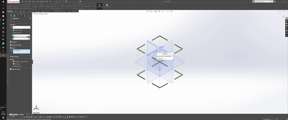
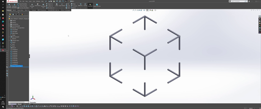
After patterning the corners to the rest of the cube, I used 8 combine’s to join the disjoint bodies in each of the corners. On reflection, this might not have been necessary.
At this point, I had pretty much what I wanted for my stencil. I oriented the model to isometric view.
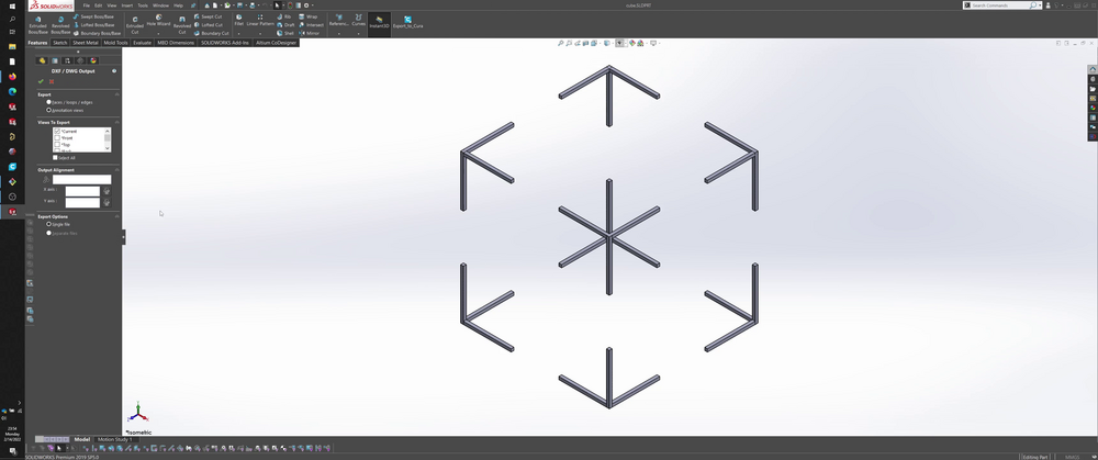
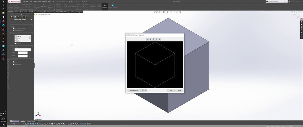
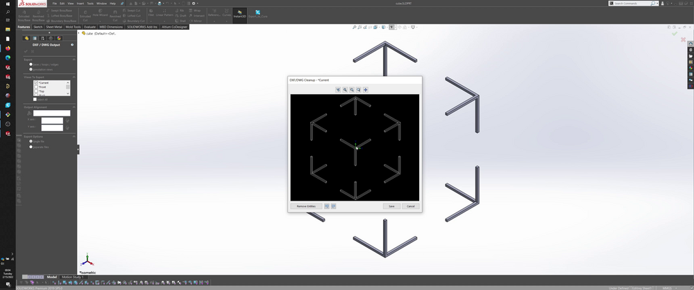
As a last touch, I also removed the back corner for the isometric implementation of the stencil.
The export dxf window shows the desired result.
Alternative results that I converged on, which are cool but didn’t fit the task >
Corners:
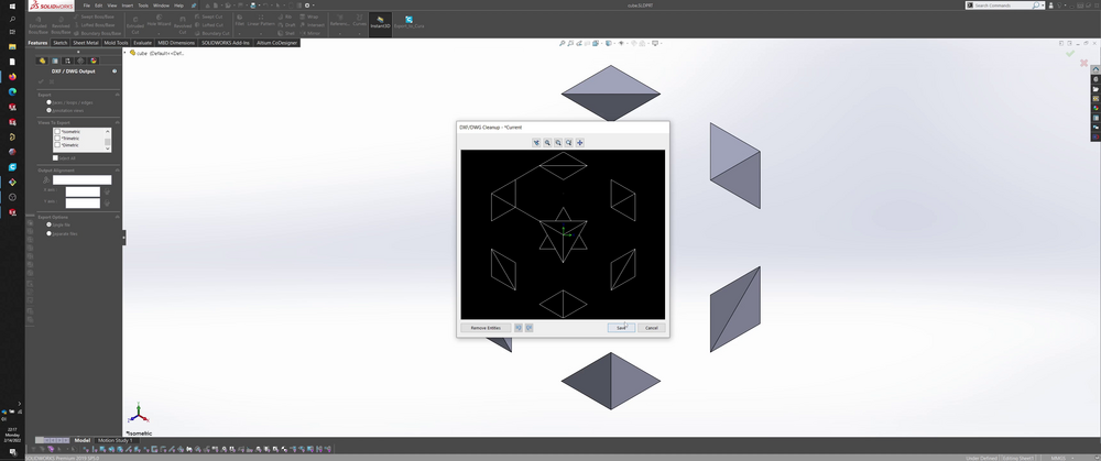
Crazy polyhedra:
Inkscape >
I imported the dxf into Inkscape and repositioned/resized the art to better fit the end use.
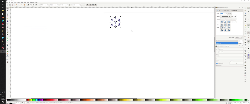
I spent some time experimenting and attempting to figure out how to create an outline of the imported elements, and eventually found a tutorial that described how to create an outline from any raster or vector image.
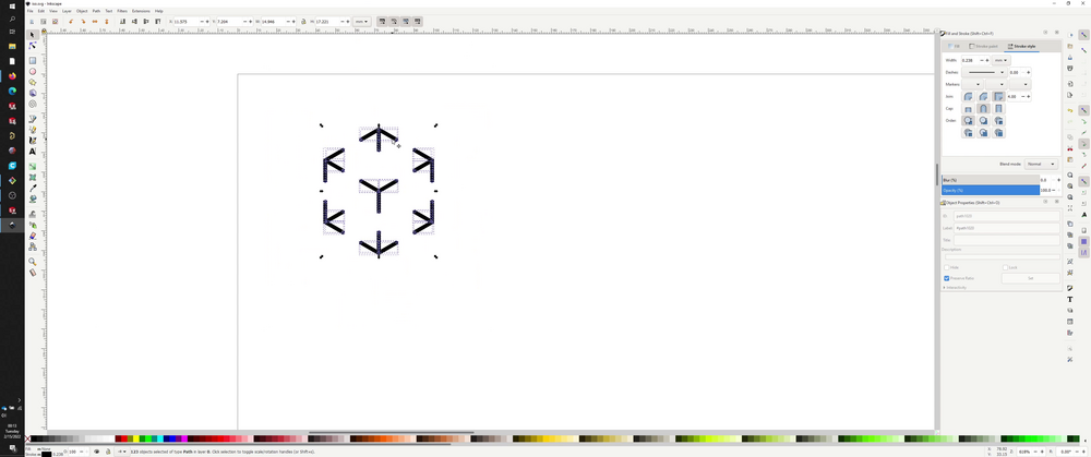
The basic steps for converting a raw dxf from Solidworks to outlined path, ready for any CNC process:
-
Select geometry
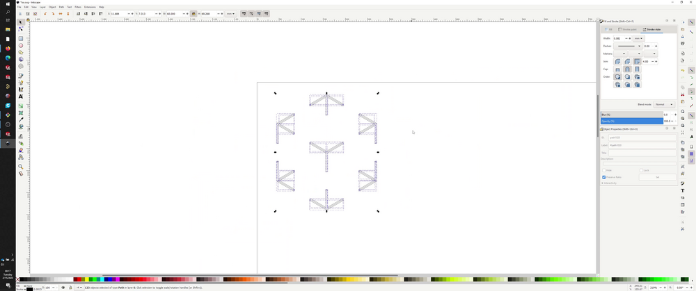
-
Path > Combine
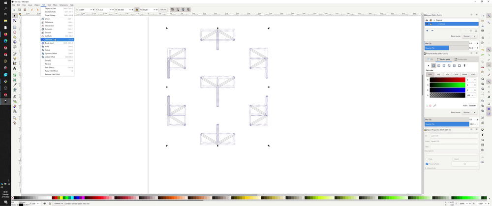
-
Change width under Fill and Stroke > Stroke style to be desired thickness (at least enough to overlap elements)
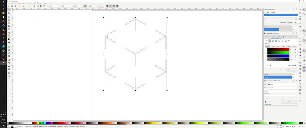
-
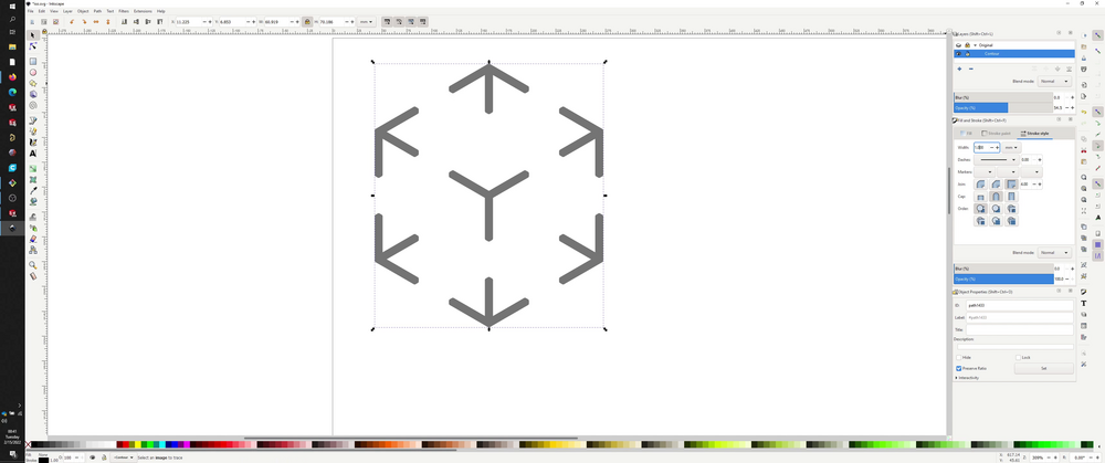
Path > Stroke to Path
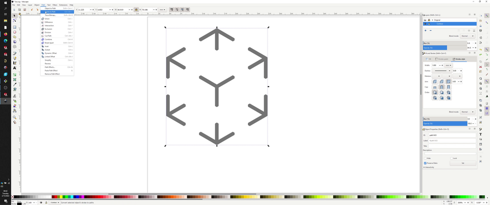
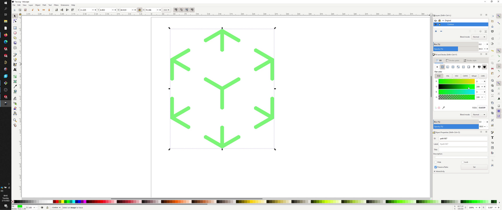
Verify by going to Fill and Stroke > Fill and changing colors. The entire pattern should change to match. This confirms that the artwork is a single path (with fill).
Silhouette Studio >
Silhouette Studio doesn’t appear to support svg’s in its free edition; not sure about the premium edition. It does appear to support dxf’s, though, so I kept my file as a dxf and imported that into Silhouette Studio.
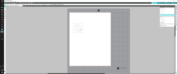
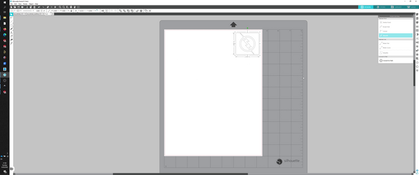
I made sure to position the artwork in the top left corner and drew a rectangle around the artwork.
Onhand, I had some overhead projection sheets that I had left over from old PCB projects; I previously used this material for making solder stencils.
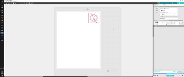
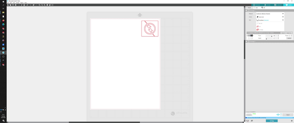
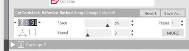
From previous experimentation, I had created the following settings for this material:
I had originally created some of these settings intending to fix a bug, so I re-evaluated the efficacy of these settings by reducing the passes from 4 to 1.
However, I discovered that making 4 passes vs a single pass can be the difference between separating the material and only partially cutting the material. In fact, it sometimes takes more than 4 passes!
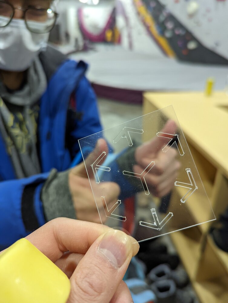
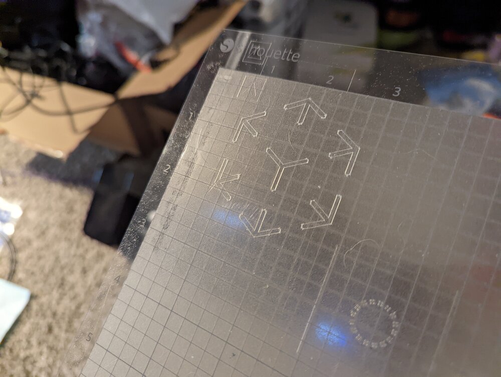
Final result >
in the background: my friend who originally suggested the idea
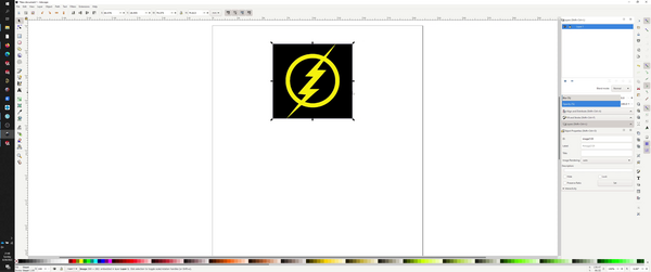
flash sticker >
went back and tried seeing how easy it would be to make an arbitrary sticker using media from the internet.
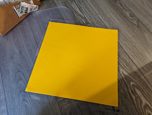
I used yellow glossy adhesive-backed vinyl for this project.
found the following flash logo from an ebay vendor.
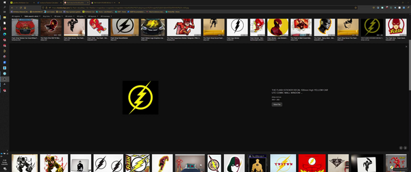
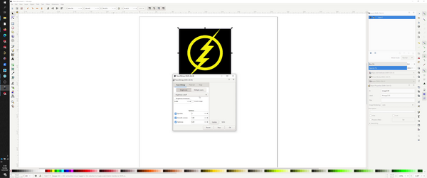
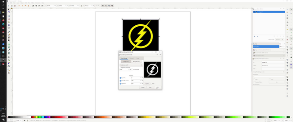
trace bitmap >
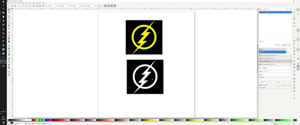
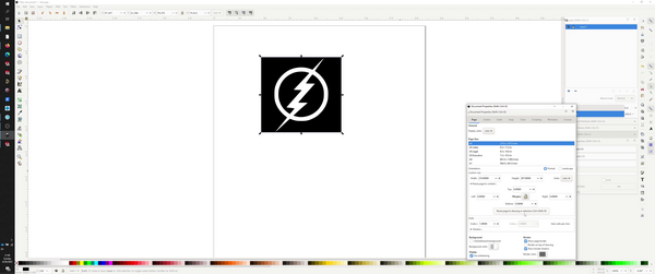
resize page to fit >
import into silhouette studio >
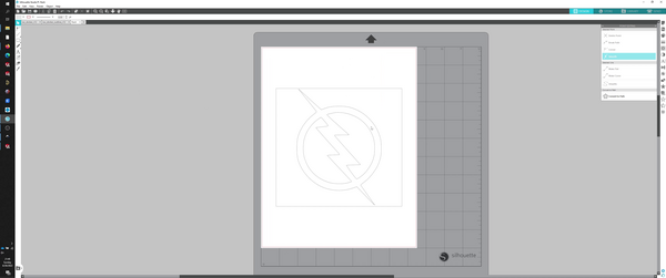
cut settings >
had to experiment with the settings a bit. when in doubt, leaned towards more force, slower travel, and deep cuts.
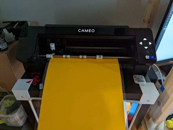
cutting >
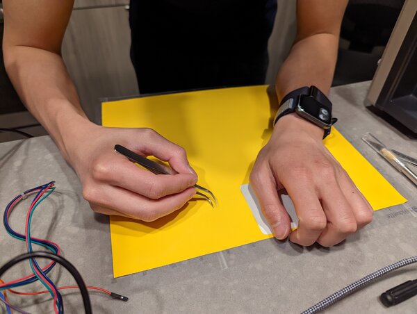
weeding >
hero shot >